Maxima and Minima: Locating the Section Where the Moment Governs the Design
Locating the section where the bending moment governs a beam is a maxima and minima problem from Calculus I: find the absolute extreme of M(x) on a closed interval. Here is the closed-interval method, its three traps, and four worked examples checked on a live FEM engine.
Key takeaways
- Sizing a beam is a maxima and minima problem: the governing section is the absolute extreme of the moment function M(x) on the closed interval from 0 to L.
- The moment peaks where its derivative is zero, and its derivative is the shear, so a smooth interior maximum sits where V(x) crosses zero.
- Setting dM/dx = 0 is not enough. An extremum can also sit at a corner where the derivative does not exist (under a point load) or at an endpoint (a cantilever peaks at the wall).
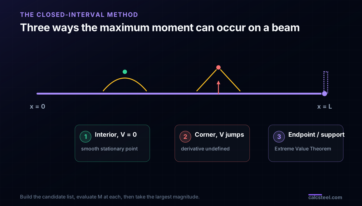
- The closed-interval method is the full recipe: list interior stationary points, non-differentiable points and endpoints, then take the candidate with the largest magnitude.
- The second derivative equals minus the load, so a downward load makes M concave down and any interior critical point a maximum. The peak moment then sets the required section modulus, W is at least M over f_yd.
The one exam question that never leaves you
Somewhere in the first semester of an engineering degree, a calculus lecturer draws a curve on the board, marks the highest point, and says: find where the derivative is zero. It feels like a puzzle with no owner. Two years later the same student is sizing a steel beam and hits the exact same question wearing a hard hat: where along this beam is the bending moment largest, and how large is it? That single number, and the section where it lives, decides how big the beam has to be. Get it right and the member is safe and lean. Get it wrong and you either waste steel or, worse, undersize the one cross-section that actually governs.
This is the article that ties the two moments together. Locating the section where the bending moment governs the design is a maxima and minima problem, the same one from Calculus I, applied to a real beam. The bending moment is a function M(x) along the length of the member. The design cares about one thing above all: the largest magnitude that function reaches, and the coordinate x where it happens. Finding it is not intuition and it is not luck. It is the closed-interval method every calculus course teaches, and it has three traps that catch students and practising engineers alike.
We wrote it for three readers at once. If you are a student, this is where the max and min chapter finally earns its keep. If you are a calculist or an independent designer, it is a clean re-derivation of the one habit that keeps Mmax from hiding. Every worked number below was produced by the CalcSteel finite-element engine and checked against the textbook closed form to the fourth decimal.
You can drive the math yourself as you read: the free shear and moment diagram calculator draws M(x) and V(x) for any beam, and it runs in your browser with no login for the math.
Why the governing section is a maxima and minima problem
Along any beam the bending moment is a function of position, written M(x), where x is the distance from one end. Sizing the beam means finding the absolute maximum of the magnitude of M(x) over the whole length, because the stress in the extreme fibre is proportional to the moment there. The section that carries that peak is the section that governs the design.
That is the entire connection in one paragraph. In a calculus course you are handed an abstract function and asked for its maximum on a closed interval. In a design office you are handed a beam, and the interval is its own length, from x = 0 to x = L. The function M(x) is not abstract at all: it is the internal couple the material must resist to keep each imagined slice of the beam in equilibrium. The maximum of that function is not a grade on a problem set. It sets the required size of a real member.
Once the peak moment Mmax is known, the rest of the beam calculation follows almost mechanically. The required section modulus is W ≥ Mmax / fyd, where fyd is the design strength of the steel. A bigger Mmax demands a deeper or heavier section. So the whole economy of the member rides on one coordinate and one value, and both come straight out of a maxima and minima analysis.
The catch is that M(x) is rarely a smooth textbook parabola. Real beams carry point loads, sit on supports part way along, and cantilever past their last support. Each of those features changes how the maximum shows up, and the naive rule, set the derivative to zero, misses two of the three ways it can happen. The next sections take them one at a time.
The first derivative of the moment is the shear
The reason calculus locates the peak so cleanly is a single relation that every beam obeys. Make an imaginary cut, balance the piece, and you find that the slope of the moment curve at any point equals the shear force there:
dM/dx = V(x)
This is the derivative from Calculus I made physical. The shear V is the rate of change of the moment. We unpack why in a dedicated piece on the derivative as a rate of change, but the consequence is what matters here. A smooth interior maximum of M happens exactly where its derivative is zero, and since that derivative is V, the moment peaks where the shear crosses zero. This is the first of the three candidate types, and the one most people remember.
There is a second relation stacked on top of it. The slope of the shear diagram is the negative of the distributed load, dV/dx = −w. Differentiate M twice and you get the second derivative:
d2M/dx2 = dV/dx = −w(x)
That is the concavity test from calculus, and it does real work here: under a downward load w > 0 the second derivative is negative, so M is concave down and any interior critical point is a local maximum. Under an upward pull the curvature flips and you get a minimum. The sign of the load tells you, before you compute anything, which way the peak points. We follow that thread into deflection in the second derivative and curvature.
Candidate 1: the interior point where the shear is zero
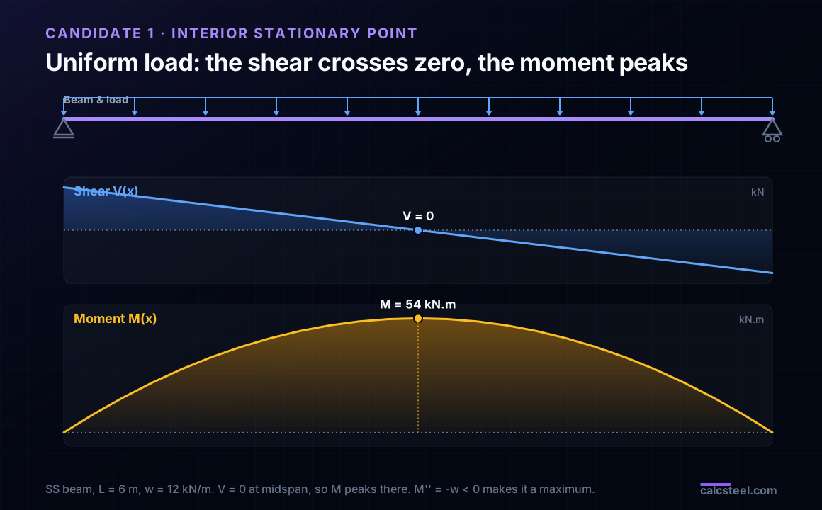
Start with the cleanest case, the one that behaves exactly like the calculus textbook. Take a simply supported beam, span L = 6 m, carrying a uniform load w = 12 kN/m across its whole length. Pin at one end, roller at the other. This is the smooth parabola every course draws first.
Reactions and shear
By symmetry each support carries half the total load: R = wL / 2 = 12 × 6 / 2 = 36 kN. The shear starts at +36 kN at the left support and falls at a constant 12 kN per metre, because dV/dx = −w. It reaches zero at the middle, x = 3 m, and keeps dropping to −36 kN at the right support.
Set the derivative to zero
The moment is largest where dM/dx = V = 0. The shear is zero at x = 3 m, so that is the critical point, and here it is a genuine interior stationary point: the slope of M is exactly zero and the curve is smooth through it. The moment there is the textbook closed form Mmax = wL2 / 8 = 12 × 62 / 8 = 54 kN·m.
Confirm it is a maximum, not a minimum
The second derivative is d2M/dx2 = −w = −12, which is negative, so the curve is concave down and x = 3 m is a maximum. No sign ambiguity, no second guessing. When we ran this beam through the CalcSteel FEM engine it returned R = 36 kN, V = 0 at x = 3 m, and Mmax = 54.000 kN·m at midspan, an exact match with theory. This is the case where the naive rule works perfectly, which is exactly why it lulls people into trusting it everywhere.
Candidate 2: the corner where the derivative does not exist
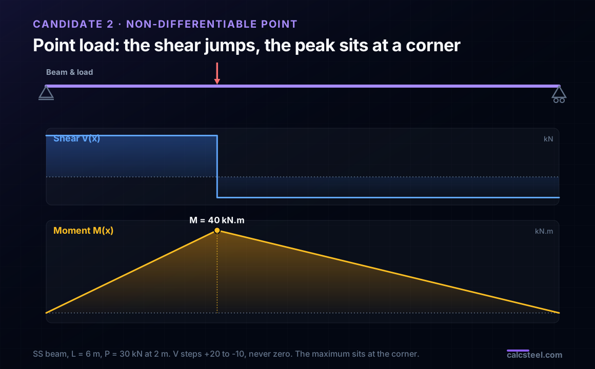
Now break the smoothness. Same simply supported span, L = 6 m, but replace the uniform load with a single point load P = 30 kN at a = 2 m from the left support, so b = 4 m to the right. A concentrated force does something a distributed load never does: it makes the shear jump.
Reactions and the jump in shear
Moments about the left support give RB = P·a / L = 30 × 2 / 6 = 10 kN, and vertical equilibrium leaves RA = P − RB = 20 kN. To the left of the load the shear is a constant +20 kN. At x = 2 m the 30 kN force drops it instantly to −10 kN. The shear never passes smoothly through zero: it steps across it. You can confirm the split with the free beam reaction calculator.
Why setting the derivative to zero fails here
If you insist on solving dM/dx = V = 0, you find no solution, because V is +20 on one side and −10 on the other and is never zero anywhere. A student who trusts the naive rule concludes there is no maximum, which is absurd: the beam obviously bends. The resolution is the part of the calculus theorem people forget. An extremum can also occur where the derivative does not exist. At x = 2 m the moment curve has a sharp corner, a kink, and the derivative is undefined there precisely because it jumps from +20 to −10. That corner is a critical point every bit as valid as a smooth stationary point.
The value at the corner
The moment climbs under the constant +20 kN shear to a peak directly under the load and then falls, giving a triangular diagram. The peak is the textbook closed form Mmax = P·a·b / L = 30 × 2 × 4 / 6 = 40 kN·m at x = 2 m. The CalcSteel engine returned exactly 40.000 kN·m at x = 2 m. The governing section sits under the load, at a point where the derivative does not even exist. Miss that second candidate type and you can miss the maximum entirely.
Candidate 3: the endpoint the interior never reaches
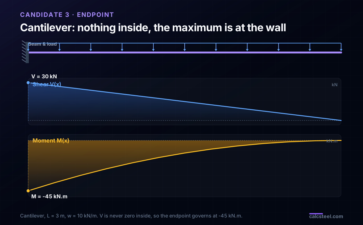
The third trap is the one that empties the interior of candidates altogether. Take a cantilever, length L = 3 m, built into a wall at the left end and free at the right, under a uniform load w = 10 kN/m. Where is the moment largest?
The shear is never zero inside the span
Measuring x from the fixed end, the shear at any section equals the load still hanging past it, V(x) = w(L − x). At the free tip that is zero, and at the wall it is the full wL = 10 × 3 = 30 kN. Between the two it is strictly positive everywhere. There is no interior point where V = 0, so candidate type 1 gives you nothing, and there is no point load, so candidate type 2 gives you nothing either. If those were the only places you looked, you would find no maximum at all.
Check the endpoints
Here the Extreme Value Theorem does the saving. A continuous function on a closed interval attains its maximum somewhere, and if not in the interior, then at an endpoint. The moment is M(x) = −w(L − x)2 / 2, zero at the free tip and largest in magnitude at the wall: M = −wL2 / 2 = −10 × 32 / 2 = −45 kN·m at x = 0. The minus sign is hogging: the load bends the cantilever so the top fibre stretches. The CalcSteel engine reproduced −45.000 kN·m at the fixed support and a support shear of 30 kN. The governing section is the endpoint, the one place the smooth rule would never send you.
This is the classic reason a cantilever beam is checked at its root and a support reaction is never an afterthought. The endpoints are always on the candidate list.
The closed-interval method, stated once for beams
The three worked cases are not three tricks. They are the three exhaustive ways a continuous function reaches its extreme value on a closed interval, which is a theorem, not a coincidence. Calculus calls the procedure the closed-interval method, and stated for a beam it reads:
- Interior stationary points. Find every x inside the span where dM/dx = V = 0. These are the smooth peaks and valleys.
- Interior non-differentiable points. Add every x where the slope of M is undefined: under each concentrated load, where the shear jumps, and at any applied concentrated moment, where M itself jumps.
- Endpoints. Add x = 0 and x = L, and every support, because a fixed end or a reaction can carry the extreme value.
- Evaluate and compare. Compute M at every candidate on the list and take the one with the largest magnitude. Sagging or hogging, positive or negative, the design cares about the biggest absolute value.
Every determinate beam in the world yields to those four steps, and so does the calculator, just faster. The list is short precisely because the theorem promises the maximum cannot hide anywhere else. What changes from beam to beam is only which candidates exist: the uniform beam had one interior stationary point, the point-load beam had one corner, the cantilever had only endpoints. Build the list, evaluate it, compare. That habit is the whole skill.

When two candidates compete: the overhang
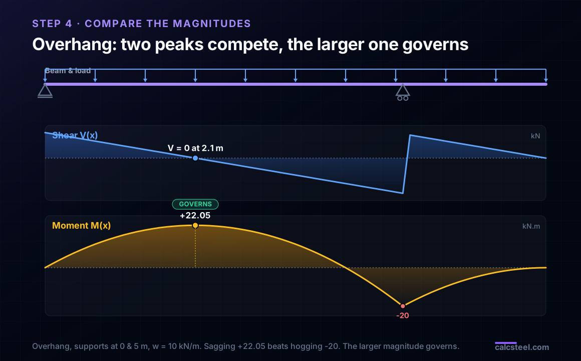
The fourth step, compare the magnitudes, is not busywork. Plenty of beams produce two serious peaks in different places, and the larger one is not always where a hurried check would look. The overhang is the everyday example. Take a beam 7 m long carrying a uniform load w = 10 kN/m, propped at x = 0 and again at x = 5 m, so the last 2 m hang past the second support as a cantilever tail.
Two candidates, two curvatures
The reactions come out to RA = 21 kN and RB = 49 kN, the far support taking more because the tail leans on it. Walking the shear from the left, it starts at +21 kN and falls at 10 kN per metre, crossing zero at x = 2.1 m. That is candidate type 1, an interior stationary point, and the moment there is a sagging peak of +22.05 kN·m. Over the second support the diagram dives into hogging, reaching −20 kN·m at x = 5 m, where the reaction puts a corner in the shear. Two peaks, opposite signs, five metres apart.
The comparison decides the beam
A designer who grabs the support moment out of habit would size the beam for 20 kN·m and be wrong. The governing value is the larger magnitude, the 22.05 kN·m sagging peak at x = 2.1 m, not the −20 kN·m over the support. The CalcSteel engine confirmed all of it: RA = 21 kN, RB = 49 kN, a sagging 22.05 kN·m at x = 2.1 m and a hogging −20 kN·m over the support. Both peaks still matter for design, the sagging one sizes the bottom fibre at midspan and the hogging one governs the top fibre and its bracing over the support, but only the comparison tells you which section is the critical one. Skip step four and the whole method can still hand you the wrong answer.
From the peak moment to the section that carries it
Locating Mmax is not the end of the story, it is the start of the beam design. The peak moment is what converts into a required size. The extreme-fibre stress is σ = M / W, where W is the section modulus of the cross-section, so keeping the stress under the design strength fyd demands W ≥ Mmax / fyd. Every kN·m you found at the governing section flows straight into that inequality and sets the smallest beam that survives.
This is why the location matters as much as the value. The section modulus a rolled shape offers depends on how far its material sits from the neutral axis, which is a story told by the moment of inertia. A deep beam earns a large W cheaply, which is why depth beats raw weight. The governing section is where that capacity gets spent, so it is where the engineer looks first, adds a stiffener if the web is thin, and checks the lateral bracing if the moment is hogging and the top flange is in compression.
The same maxima and minima habit scales past a single beam. In a continuous beam the interior support is usually the governing hogging section, and in a rigid frame the peak migrates to the knee. The tool changes, hand statics for the simple beam and a finite-element solver for the frame, but the question never does: build the candidate list, evaluate M at each, take the largest magnitude, size the section there.
Try it: watch the shear cross zero and the moment peak
The fastest way to make the closed-interval method stick is to move a load and watch the peak move with it. The calculator below is the same one the worked examples were checked against. Set a span, add a uniform load or a point load, and read the two diagrams live: the shear V(x) on top, the moment M(x) below.
Three things to look for, one per candidate type. Drag a point load off-centre and notice the shear steps through zero while the moment peaks at the corner beneath it. Switch to a uniform load and watch the shear cross zero smoothly at midspan, where the moment is a clean parabola. Prop the beam short of its end to make an overhang and compare the two peaks that appear. The picture the calculus predicts is the picture the engine draws.
It is free, runs in the browser, and needs no login for the math. When you are ready for the full picture from beam to frame, the shear force and bending moment diagram guide carries it the rest of the way.
|V| max
30 kN
@ x = 6 m
M max (sagging)
45 kN·m
@ x = 3 m
M min (hogging)
-0 kN·m
@ x = 6 m
Reactions (kN)
R_A 30 · R_B 30
Simply supported beam — uniformly distributed load
Segment equations — x in m, from the left end
0 m ≤ x ≤ 6 m
V(x) = 30 − 10·x [kN]
M(x) = 30·x − 5·x² [kN·m]
Profiles that resist this moment
Md = 45 kN·m → required Wx = Md / (fy/γa1) = 45 kN·m / (250/1.1) = 198 cm³
Bending screen (Wx ≥ Md/(fy/γa1), NBR 8800 γa1 = 1.10 — AISC 360 φb = 0.90 is nearly identical); plastic Zx is valid for compact sections only. δ is the elastic deflection of THIS loading with E = 200 GPa and the section's Ix (loads taken at service value). LTB, shear, compactness and code deflection limits are verified on the profile page and in the 3D editor. "Open in 3D editor" recreates THIS beam — span, supports and every load — with the profile already assigned.
The four mistakes that hide the maximum
Almost every wrong answer traces to one of four habits, and each one is a candidate type left off the list.
- Assuming the peak is always at midspan. True only for a symmetric load on a symmetric span. Move the load off-centre and the peak moves under it. Midspan is a candidate, not a rule.
- Solving only dM/dx = 0. That finds the smooth interior peaks and nothing else. Under a point load the shear jumps and the derivative never equals zero, yet the moment is maximal at that very corner. Non-differentiable points belong on the list.
- Forgetting the endpoints. A cantilever has its worst moment at the wall, where the interior offers no stationary point at all. Endpoints and supports are always candidates, by the Extreme Value Theorem.
- Skipping the magnitude comparison. An overhang or a continuous beam gives a sagging peak and a hogging peak in different places. Grabbing the first one you compute, or the one at the support, can understate the governing moment. Evaluate every candidate, then take the largest absolute value.
A fifth, rarer trap: an applied concentrated moment makes M itself jump, not just its slope, so the extreme value can sit immediately to one side of it. Same cure. Put the jump on the candidate list and evaluate both sides.
The calculus you already know, pointed at a beam
Maxima and minima stops being an abstract chapter the moment you see it sizing steel. The bending moment is a function on a closed interval, the governing section is its absolute extreme, and the closed-interval method finds it without fail: interior stationary points where the shear is zero, non-differentiable corners under point loads, the endpoints and supports, then the largest magnitude among them. Three candidate types, one comparison, no guesswork.
If this connected two halves of your coursework, the rest of the series continues the thread. The derivative as a rate of change explains why dM/dx = V. The second derivative and curvature takes the concavity test into deflection. The definite integral shows why the area under the shear is the moment, and where integrals show up across structural engineering maps the rest. When the beam becomes a frame, the shear and moment diagram guide carries the same habit all the way to a portal frame.
The next time a calculus problem asks for a maximum on a closed interval, you will recognise it. It is a beam waiting to be sized.
Sources
- 1.James Stewart, Calculus: Early Transcendentals, Chapter 4 (Applications of Differentiation), the Closed Interval Method and the Extreme Value Theorem
- 2.R. C. Hibbeler, Structural Analysis, Chapter 4 (Internal Loadings, Shear and Moment Diagrams)
- 3.F. P. Beer, E. R. Johnston, Mechanics of Materials, Chapter 5 (Analysis and Design of Beams for Bending)
- 4.AISC 360-22 Specification for Structural Steel Buildings, Chapter F (Design of Members for Flexure)
Try CalcSteel for free
Model, analyze and design steel structures in your browser. No install, no signup.
Open the 3D editor