Unsymmetric Bending: What Happens When the Load Misses the Principal Axis
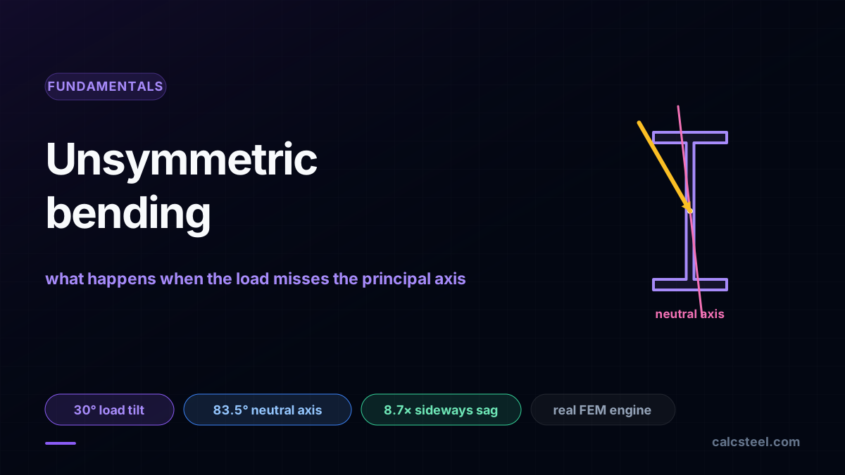
Bending theory hands you one clean formula, sigma = M·c / I, and it is exact right up to the moment the load stops lining up with a principal axis of the section. Tilt the load a little, or let a purlin follow a roof slope, and the beam quietly starts bending about both of its axes at once. The neutral axis swings away from the load, the beam deflects sideways, and the peak stress jumps to a corner you were not watching. This guide runs the real CalcSteel engine on a W360 beam and a channel purlin to show exactly what unsymmetric bending does, why the small weak axis does most of the damage, and how to size for it: split the load onto the two principal axes, solve each, and add.
Key takeaways
- A principal axis is a direction in which pure bending stays pure: load along it and the beam deflects along it. Every doubly symmetric section (I, box, tube) has two, aligned with the obvious vertical and horizontal. The instant the load misses that direction, the section bends about both axes and the simple sigma = M·c / I no longer tells the whole story.
- On the CalcSteel engine, a 6 m simply supported W360 that is safe under a vertical 100 kN load (172 MPa, 49% of yield) is driven to 761 MPa (217% of yield) by the SAME load tilted just 30 degrees. The load barely moved; the stress more than quadrupled.
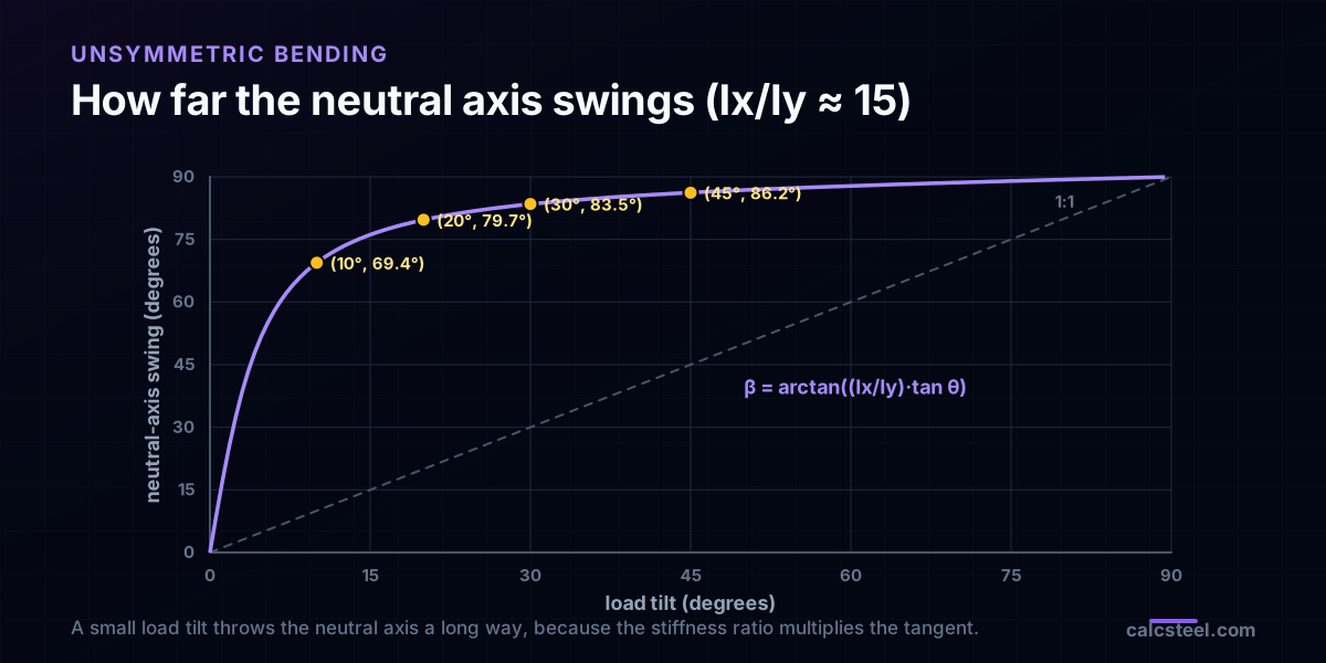
- The neutral axis does not follow the load, it runs ahead of it, amplified by the ratio of the two second moments: tan(beta) = (Ix / Iy)·tan(theta). With Ix / Iy close to 15 for a wide flange, a 30 degree load tilt throws the neutral axis to 83.5 degrees, and the engine deflection agrees at every angle we tested.
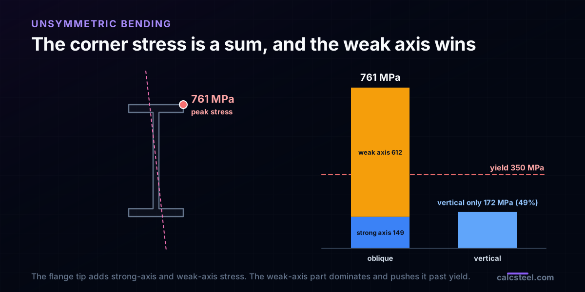
- The weak axis does most of the harm because its section modulus is tiny. In the worked beam the weak-axis moment is only 75.0 kN·m against 129.9 kN·m on the strong axis, yet it produces 612 MPa against 149 MPa, because Sy is about 7.1 times smaller than Sx.
- Unsymmetric bending is just two ordinary bending problems stacked. Resolve the load onto the two principal axes, solve each on its own, and add the moments, the stresses and the deflections. The engine confirms the split is exact to the third decimal.
The load goes down, the beam goes sideways
Here is a result that catches almost every student the first time. Take a normal steel beam, a wide-flange section standing upright the way beams are drawn. Load it straight down and it behaves: it sags, and the sag is small. Now tilt the same load by a modest angle, the kind of tilt you get from a sloped roof or a load hung slightly off to one side, and the beam does something it has no right to do. It deflects mostly sideways, and the stress in it climbs far faster than the tilt would suggest.
We will put numbers on it in a moment, from the real CalcSteel solver, and they are stark: a W360 that is at 49% of yield under a vertical load hits 217% of yield under the very same load tilted 30 degrees. Nothing about the load got heavier. It just stopped pointing along a principal axis of the section. That is the whole subject of this article, and it has a name: unsymmetric bending, or biaxial bending, the bending you get when the load misses the axis the section wants to be loaded on.
None of this is exotic. It is the everyday mechanics of purlins on a pitched roof, of angle members that have no upright axis at all, of crane rails pushed sideways, of any beam a designer orients by eye. The good news is that it is completely predictable, and once you see the two principal axes and how a load splits onto them, it becomes easy to size for.
What a principal axis actually is
Every cross-section has a special pair of perpendicular axes through its centroid called the principal axes. They are the directions for which the product of inertia is zero, and that zero is what matters. Bend a beam about a principal axis and the response is clean: the beam deflects in the same plane as the load, the neutral axis lies along the other principal axis, and sigma = M·c / I is exact. Bend it about any other axis and the two planes couple, which is the coupling this whole article is about.
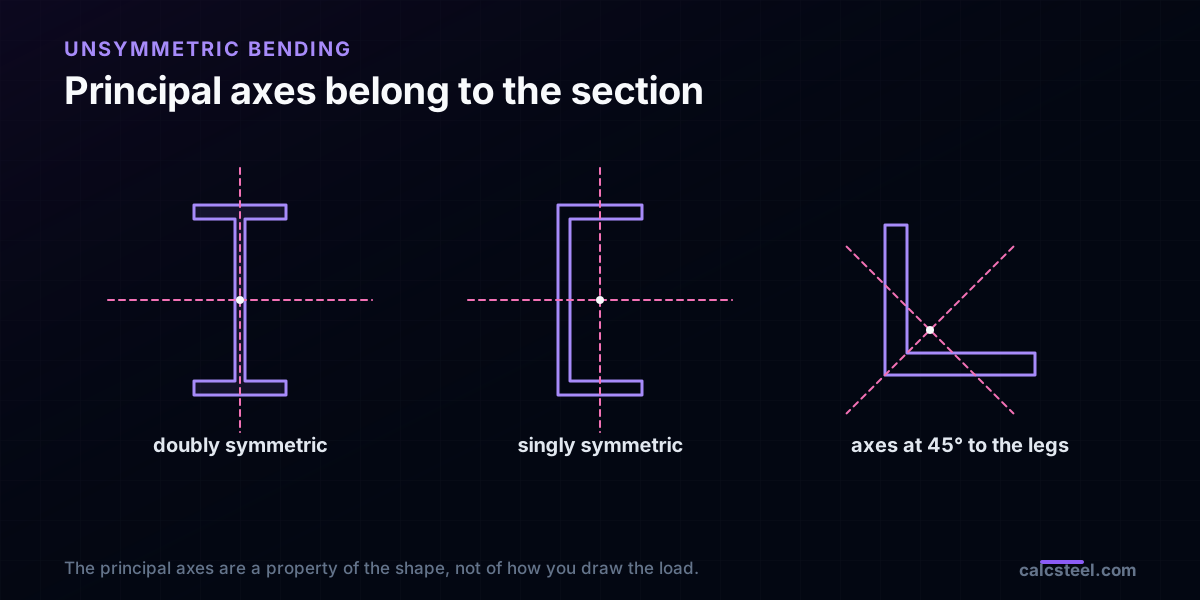
For the friendly sections, you already know where the principal axes are. A doubly symmetric shape, an I-beam, a rectangular box, a round tube, hands them to you for free: any axis of symmetry is automatically a principal axis, so the vertical and horizontal centrelines are the two you want. That is precisely why we draw beams upright. Loaded vertically, an upright I-beam is being loaded on a principal axis, and everything is simple.
The trap is that the principal axes belong to the section, not to gravity. If the section is rotated (a purlin tilted with the roof) or if it simply has no vertical axis of symmetry (an angle, a Z), then the principal axes are tilted too, and a plain vertical load no longer lands on one. Finding those axes for a general section is a job for a moment of inertia calculation, and for symmetric shapes the symmetry of the section hands them over without any work at all.
A section has two bending stiffnesses, and one is a trap
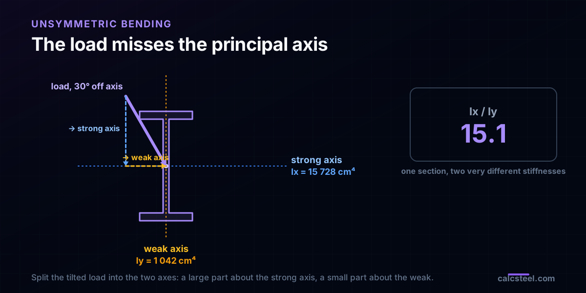
Along its two principal axes a section has two second moments of area, and for a wide flange they are wildly different. Take the W360 we use below. About the strong axis it offers Ix = 15 728 cm⁴; about the weak axis only Iy = 1 042 cm⁴. That is a stiffness ratio of about 15 to one. The whole point of a deep I-shape is to pile material far from the strong axis, which is exactly what makes the weak axis so feeble by comparison.
Stiffness governs deflection, but stress is governed by the section modulus, and there the gap is just as brutal. The strong-axis modulus is Sx = 874 cm³; the weak-axis modulus is only Sy = 123 cm³, about 7.1 times smaller. That single number is the villain of this story. A given moment carried on the weak axis produces several times the stress it would on the strong axis, so even a small slice of the load leaking onto the weak axis lands a heavy blow. The section modulus you never quote is the one that gets you.
So a section is not one beam, it is two, sharing the same steel: a stiff, strong one and a flimsy, weak one at right angles. Load along either principal axis and only that beam responds. Load in between and both respond at once, each in proportion to how much of the load points its way, and the flimsy one punches above its share.
The neutral axis rotates, and the rotation is amplified
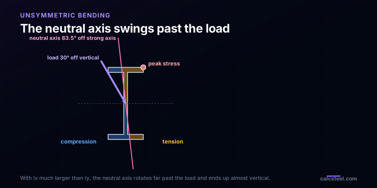
Under uniaxial bending the neutral axis is easy: it is the other principal axis, the line of zero stress the section rotates about. Under an oblique load the neutral axis tilts, and here is the surprise, it does not tilt with the load. It tilts past it, and the amplifier is the stiffness ratio:
tan(beta) = (Ix / Iy)·tan(theta),
where theta is how far the load leans off vertical (off the strong-axis loading direction) and beta is how far the neutral axis rotates off the strong axis. The section is stiff about the strong axis and soft about the weak one, so it gives way far more in the weak direction, and the plane it actually bends in swings hard toward the weak axis.
Run the numbers for the W360. Its ratio is about 15, so a load tilted only 30 degrees off vertical drives the neutral axis to tan(beta) = 15·tan(30 degrees), which is beta = 83.5 degrees. The load barely leaned over, yet the neutral axis has rotated almost a full quarter turn, swinging from horizontal to nearly vertical. Because the beam always deflects perpendicular to its neutral axis, the deflection swings the same amount the other way, off vertical and almost fully sideways. Get the neutral-axis angle and you have already predicted both the stress pattern and the direction the beam will move.
How far the neutral axis swings
The amplification is worth seeing across a range of load angles, because it is so front-loaded. We ran the W360 through the engine at four load tilts and measured the neutral-axis swing from the deflection direction it produced, then compared it against the formula. They agree at every angle:
- Tilt the load 10 degrees off vertical and the neutral axis swings 69.4 degrees off the strong axis.
- Tilt it 20 degrees and the neutral axis is already at 79.7 degrees.
- Tilt it 30 degrees and it reaches 83.5 degrees.
- Tilt it 45 degrees and it is 86.2 degrees, nearly vertical.
The first ten degrees of tilt do most of the work. That is the practical warning: with a high strong-to-weak ratio there is no gentle onset. A load you thought was almost vertical is already bending the section almost entirely about its weak axis. This is the same stiffness asymmetry that governs lateral-torsional buckling and weak-axis column buckling, where the feeble axis is again the one that decides the outcome.
A worked beam: 30 degrees of tilt, and the damage
Now the full worked case on the CalcSteel engine, so the numbers are not hand-waving. A simply supported W360, span L = 6 m, carries a single P = 100 kN load at midspan. First we point the load straight down, then we tilt it 30 degrees and change nothing else.
Load vertical. The beam does its job. The midspan moment is Mz = 150 kN·m on the strong axis, the bending stress is 172 MPa, and the member sits at 49% of a 350 MPa yield. Comfortable. This is the beam working on its principal axis, the clean case where sigma = M·c / I is the entire story.
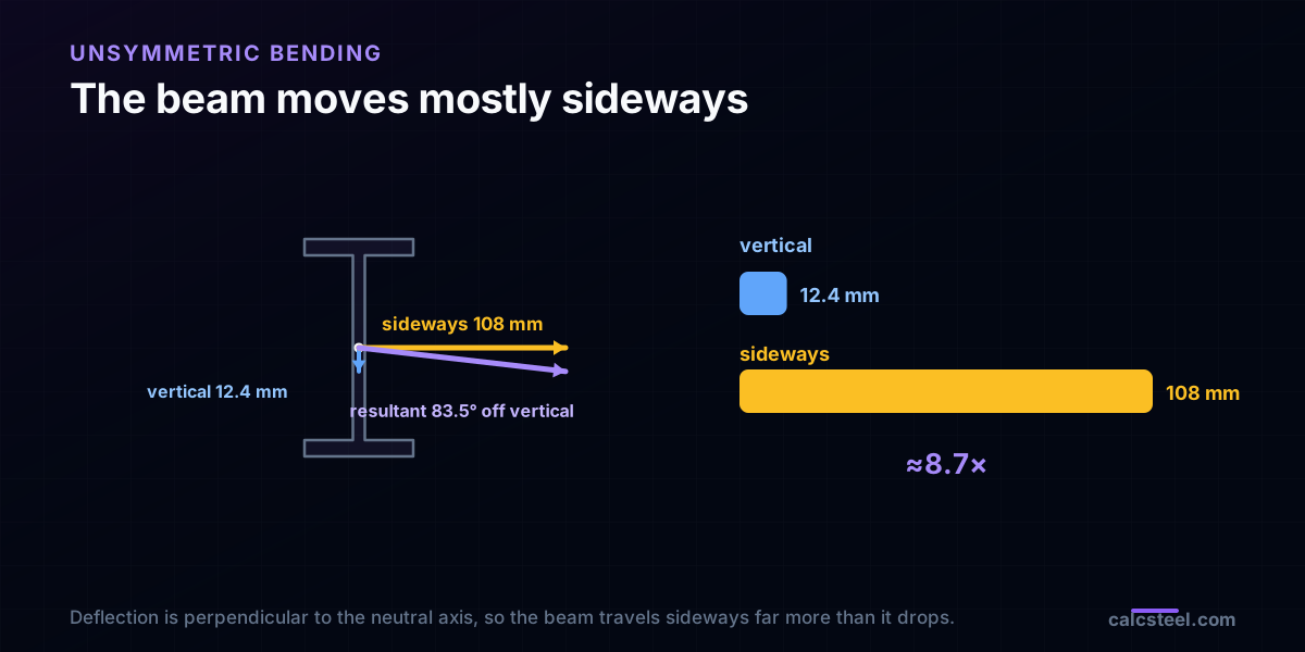
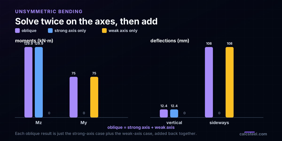
Same load, tilted 30 degrees. The load now splits into Mz = 129.9 kN·m on the strong axis and My = 75.0 kN·m on the weak axis. Notice the weak-axis moment is not small: it is well over half the strong-axis one, because tan(30 degrees) is not small. The engine returns a midspan deflection of 12.4 mm vertically but 108 mm sideways, a sideways sag about 8.7 times the vertical one. The beam is barely dropping and mostly swinging out of plane, exactly the 83.5 degree neutral-axis tilt made visible.
Those are the two diagrams a designer must learn to expect together. Bending about the strong axis you can read off a normal shear and bending moment diagram, but under an oblique load there is a second diagram, the weak-axis one, running at the same time, and it is the one that decides the corner stress in the next section.
Why the stress explodes at the corner
Under uniaxial bending the peak stress lives at the top or bottom fibre. Under an oblique load it moves to a corner, the point farthest from the rotated neutral axis, and it is the sum of the two bending contributions:
sigma = Mz·(h/2) / Ix + My·(b/2) / Iy = Mz / Sx + My / Sy.
Feed the worked beam into that. The strong-axis term is Mz / Sx = 149 MPa, the honest cost of the vertical part of the load. The weak-axis term is My / Sy = 612 MPa. Look at what happened: the weak-axis moment (75.0 kN·m) is smaller than the strong-axis one (129.9 kN·m), yet its stress is about four times larger, because it is divided by the tiny Sy = 123 cm³ instead of the generous Sx = 874 cm³.
Add them and the far corner reaches 761 MPa. Against a 350 MPa yield that is 217% utilisation: the section has yielded. The same beam under the same load pointed straight down was at 49%. The entire difference, from comfortable to failed, is the 612 MPa the weak axis contributed once the load stopped pointing along the strong one. That is why unsymmetric bending is dangerous rather than merely academic: the term you are tempted to ignore is the term that governs.
Where you meet this: the roof purlin
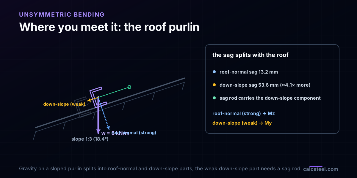
The textbook version is a load tilted by hand. The real version is a purlin. A purlin sits on a pitched roof with its strong axis following the slope, so plain vertical gravity already arrives off-axis, tilted by the roof pitch. There is no careless designer to blame here; the geometry does it for you.
We ran a C250 channel purlin on the engine, span 6 m, carrying w = 8 kN/m of gravity, on a modest 1:3 roof (a pitch of 18.4 degrees). The gravity load resolves into a component normal to the roof, carried by the channel's strong axis, and a smaller component down the slope, carried by its weak axis. The strong axis takes Mz = 34.2 kN·m and sags 13.2 mm normal to the roof. The weak axis takes only My = 11.4 kN·m, yet it sags 53.6 mm down the slope, about 4.1 times the roof-normal sag. On this channel the ratio Ix / Iy is roughly 12, and (Ix / Iy)·tan(pitch) lands right on that 4.1.
That down-slope sag is exactly why purlins get sag rods (also called sag bars or bridging) run between them at mid-span or third points. The sag rods are not there for the gravity you are thinking of; they are there to carry the sneaky weak-axis component of it, the one this article is about, before it sags the roof line visibly out of true. Leave them out and the purlins bow sideways along the slope, ponding water and pulling the sheeting.
How to handle it: solve twice on the axes and add
The method falls straight out of the theory. Because the two principal directions do not interfere, an oblique load is just a strong-axis load plus a weak-axis load, and the responses superpose. So you never solve a coupled problem. You solve two familiar uncoupled ones and add the answers, moment for moment, stress for stress, deflection for deflection.
We checked the split on the engine for the worked beam. Solved as one oblique 30 degree load it gives Mz = 129.9 kN·m, My = 75.0 kN·m, a vertical deflection of 12.4 mm and a sideways one of 108 mm. Solved instead as two separate runs, a strong-axis-only load and a weak-axis-only load, the strong run delivers all of the 129.9 kN·m and the 12.4 mm drop with zero sideways move, the weak run delivers all of the 75.0 kN·m and the 108 mm sideways sag with zero drop, and adding them reproduces the oblique case to the third decimal.
That is the recipe to carry away. Resolve the load onto the two principal axes. Run each as an ordinary bending problem, the kind any beam tool or hand method already does. Then combine: sigma = Mz / Sx + My / Sy at the governing corner, and add the deflection components as vectors. The section properties for both axes are all you need to feed it.
Angles, Zs and the sections with no upright axis
So far the section had an upright axis of symmetry, so a vertical load was off-axis only when we tilted it. Some very common sections are worse: they have no vertical axis of symmetry, so even a plain vertical load through the centroid is oblique from the start. The single equal-leg angle is the classic offender. Its axes of symmetry run along the diagonals, so its principal axes sit at 45 degrees to its legs. Load an angle vertically and it is already bending about both principal axes and trying to swing off toward its minor diagonal, which is why a lintel angle left unrestrained sags sideways.
The Z-section, another favourite purlin, is subtler still: it is point symmetric, so its principal axes are tilted by an angle you have to compute from the product of inertia. That tilt is often chosen to nearly cancel the roof pitch, which is one reason Z-purlins can outperform channels on a slope. For any of these, the honest route is to find the true principal axes and their Imax and Imin first, then apply the very same split-and-add method from the previous section. Nothing about the mechanics changes; only the axes are rotated.
One caution for the singly symmetric shapes, the channel included: loading them off the shear centre also twists them, so a full check couples unsymmetric bending with torsion. That is a larger topic, but the bending part is exactly what we have computed here, and it is usually the part that governs first.
Where designers get burned
A short field guide to the places unsymmetric bending shows up, usually uninvited:
- Purlins and girts without bridging. The down-slope component quietly sags the roof line and overstresses the weak axis. Sag rods carry it; skipping them is the classic miss.
- Single angles as beams. A lintel or a light purlin in an angle bends about its 45 degree principal axes from the first kilonewton. Check it on the true axes, not on the legs.
- Beams oriented by eye. A member rotated a few degrees during erection, or a monorail on a cambered runway, quietly leaks load onto the weak axis. A few degrees is enough, as the sweep above showed.
- Quoting only Sx. The weak-axis modulus Sy is several times smaller and does most of the damage under oblique load. If a load can arrive off-axis, Sy belongs on the calculation sheet.
- Trusting a single diagram. An oblique load has two bending diagrams. Read only the strong-axis one and you miss the term that governs the corner.
The through-line is the same in every case: a small amount of load on the weak axis buys a large amount of stress, because the weak-axis modulus is small. Respect that one fact and unsymmetric bending stops being a surprise.
Try it on your own section
The fastest way to build intuition is to look at the two numbers that decide everything for your section: its strong-axis and weak-axis second moments, and the section moduli that go with them. The calculator below is the CalcSteel moment of inertia tool, free and with no login for the maths. Pick a shape or build a custom one, and read Ix, Iy, Sx and Sy straight off. The bigger the gap between the two, the more violently the neutral axis will swing the moment a load leaves the strong axis, and the more a small weak-axis moment will cost you.
With those four numbers you can run the whole method by hand: resolve your load onto the two axes, take Mz / Sx and My / Sy, and add them at the corner. From here the natural next reads are the moment of inertia guide behind these properties, the section modulus that turns them into stress, and lateral-torsional buckling, where the same weak axis decides how a beam fails long before the material does.
Formula — hover a variable to highlight it on the drawing
Ix = [ b·h³ − (b − tw)·hw³ ] / 12= 1,845.6 cm⁴(hw = h − 2·tf)
Iy = [ 2·tf·b³ + hw·tw³ ] / 12= 141.9 cm⁴
Root fillets are neglected — rolled-section tables run 1–5% higher on Ix.
Parallel-axis theorem, live — Ix = Σ ( I₀ + A·d² )
| Part | A (cm²) | d (cm) | I₀ (cm⁴) | A·d² (cm⁴) | I₀ + A·d² (cm⁴) |
|---|---|---|---|---|---|
| Web | 10.25 | 0 | 286 | 0 | 286 |
| Flange (top) | 8.5 | 9.58 | 0.512 | 779.3 | 779.8 |
| Flange (bottom) | 8.5 | 9.58 | 0.512 | 779.3 | 779.8 |
| Σ = Ix | 287 | 1,558.6 | 1,845.6 |
Exact rectangle parts (web + two flanges) about the section centroid — the flange A·d² transfer terms are the whole story of the I-beam. Change any dimension above and watch the table re-derive.
Section properties
Moment of inertia Ix
1,845.6 cm⁴
1.846 × 10⁷ mm⁴
Moment of inertia Iy
141.9 cm⁴
1.419 × 10⁶ mm⁴
Area A
27.25 cm²
Mass
21.39 kg/m
Section modulus Sx
184.6 cm³
Section modulus Sy
28.39 cm³
Plastic modulus Zx
209.7 cm³
Plastic modulus Zy
43.93 cm³
Radius of gyration rx
8.23 cm
Radius of gyration ry
2.28 cm
Centroid x̄ (from left)
50 mm
Centroid ȳ (from bottom)
100 mm
Local slenderness — NBR 8800 / AISC 360 fingerprint
Flange
λ = b / 2·tf = 5.88
λp = 10.75 · λr = 28.28
Web
λ = hw / tw = 32.68
λp = 106.3 · λr = 161.2
Flexure limits per AISC 360 Table B4.1b (≈ NBR 8800 Annex F), fy = 250 MPa, E = 200 GPa — λp/λr scale with √(E/fy). Compact sections reach the full plastic moment Mp = Z·fy; non-compact and slender elements are capped by local buckling.
Closest standard profiles — matched by Ix against 876 real catalog sections
Ix = 1,845.6 cm⁴ (-0.0%)
Iy = 141.9 cm⁴ (-0.0%)
21.39 kg/mlightest
Best match — design checks
Ix = 1,844.2 cm⁴ (-0.1%)
Iy = 902.5 cm⁴ (+535.8%)
34.19 kg/m#2 by weight
Design checks
Ix = 1,838.7 cm⁴ (-0.4%)
Iy = 1,838.7 cm⁴ (+1195.4%)
43.96 kg/m#3 by weight
Design checks
Same 1,309-profile database that powers the CalcSteel 3D editor and profile pages — ABNT cold-formed (Ue, U, rounds), AISC (W, HSS, L, Pipe), European (IPE, HEA, HEB, HEM, UPN) and Indian (ISMB/ISMC) series. Opening a match carries your custom section along as the comparison baseline.
Try CalcSteel for free
Model, analyze and design steel structures in your browser. No install, no signup.
Open the 3D editor