Symmetry and Antisymmetry: Halving the Model Without Changing the Answer
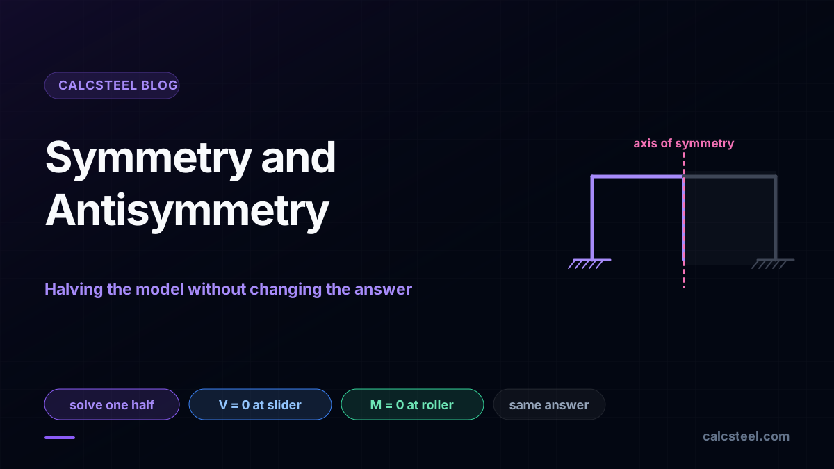
A structure that mirrors about an axis carries a quiet gift: you can throw away half of it. Model one side, put the right support on the cut, and the reactions and moments come back identical to the full model. This guide proves it on the real CalcSteel engine, a two-span beam solved on one span and a portal frame solved on one leg, then shows the rule that makes it work: every load is a symmetric load plus an antisymmetric one, and each half needs its own kind of support on the axis. Get that support right and the half-model is exact. Get it wrong and it lies.
Key takeaways
- A structure symmetric in geometry, supports and stiffness can be solved on half the model, and the engine returns the same reactions and the same moments. We prove it to the third decimal on a beam and on a frame.
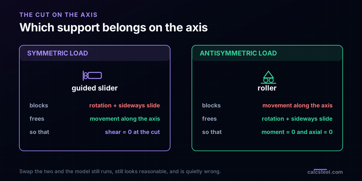
- The support on the cut depends on the load. A symmetric load takes a guided slider, which blocks the sideways movement and the rotation, so the shear is zero there. An antisymmetric load takes a roller, which blocks only the along-axis movement, so the moment and the axial force are zero there.
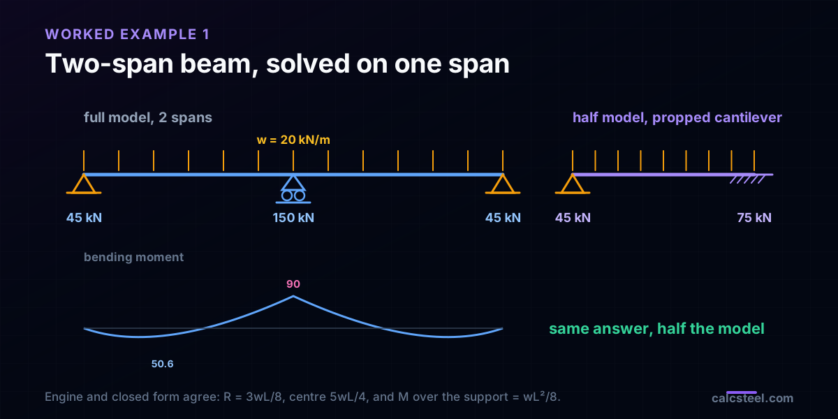
- Two-span beam under a symmetric UDL: the full model gives R_A = 45 kN, R_B = 150 kN and M_B = 90 kN·m. The half model, a single propped cantilever, returns R_A = 45 kN and M_B = 90 kN·m, matching the textbook 3wL/8 and wL²/8 exactly and independent of the section.
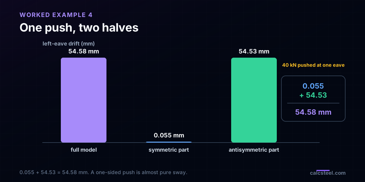
- Any load splits into a symmetric part plus an antisymmetric part. A 40 kN push at one eave of a portal drifts 54.58 mm; solving the two halves gives 0.055 mm from the symmetric part plus 54.53 mm from the antisymmetric part, which add straight back to 54.58 mm.
- Halving is not about solver speed, a modern solver eats the full model in a blink. It is a modeling and checking discipline: a symmetric model must produce a symmetric answer, so the half-model is a free error trap and a hand-check you can actually trust.
Solve half, keep the whole answer
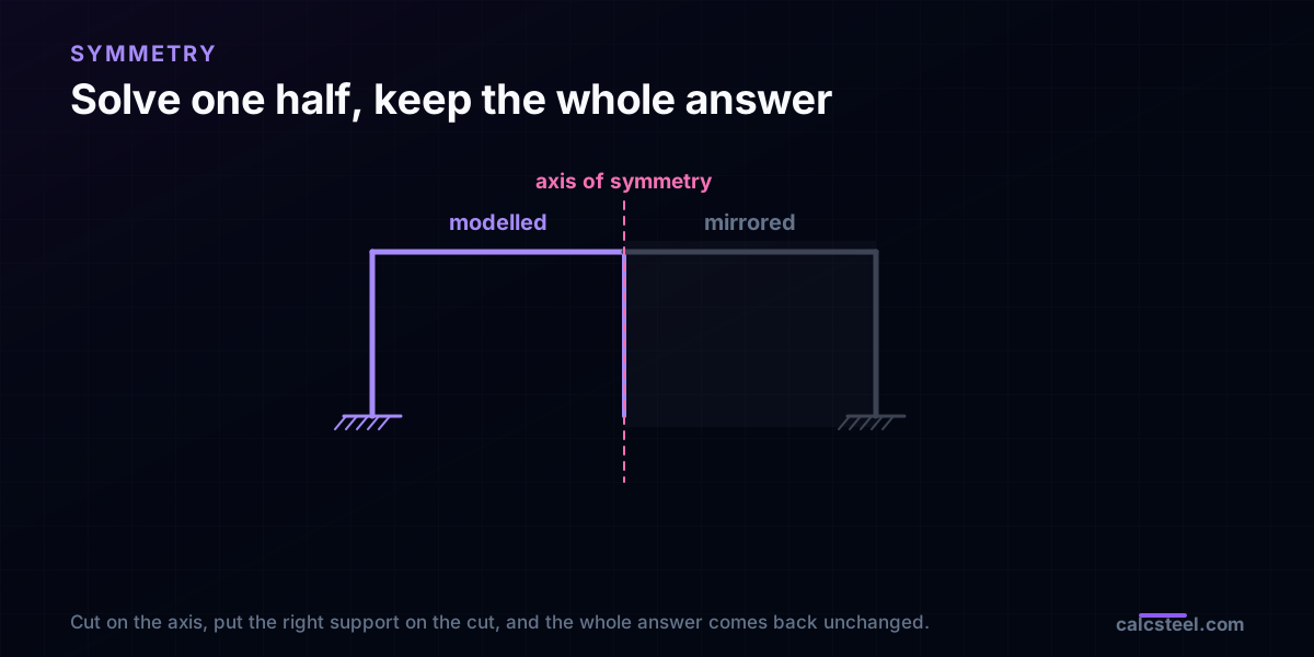
Open any first course in structural analysis and symmetry shows up early, usually as a picture: a portal frame with a dashed line down the middle, an arch that mirrors left to right, a bridge truss that reads the same from either bank. The picture is the easy part. The useful part is the claim hiding behind it: if the structure is symmetric, you do not have to solve all of it. You can cut it on the axis, keep one half, and recover the exact internal forces of the whole.
That claim deserves suspicion, because it sounds like something for free. So this article does not assert it, it runs it. We take a two-span continuous beam and a portal frame, solve each one twice, once as the full model and once as a half with the right support on the cut, and put the two answers side by side. They match to the third decimal, and on the beam they also match the closed-form textbook result. Along the way we pin down the one thing that makes or breaks the trick: which support belongs on the axis, and why it is different for a load that pushes symmetrically than for one that pushes the structure sideways.
When is a structure actually symmetric?
Symmetry is stricter than it looks. For the half-model trick to be exact, three things have to mirror about the same axis, not just one.
- Geometry. Every node and member on the left has a mirror twin on the right at the same distance from the axis.
- Stiffness. Mirror members share the same section and material, so EA and EI match twin for twin. A left column in IPE 360 and a right column in IPE 300 breaks it, even if the drawing looks balanced.
- Supports. A pin on the left needs a pin on the right, a fixed base needs a fixed base. This is the one people forget: a portal that is geometrically symmetric but pinned on one side and fixed on the other is not a symmetric structure, and halving it gives the wrong answer.
Notice what is not on the list: the load. The structure can be symmetric while the load is anything at all. That separation is the whole game. Symmetry is a property of the structure, and once the structure qualifies, we handle any load by splitting it, which is the next section. One more subtlety worth stating plainly: what has to be symmetric is the response, not just the drawing. A symmetric structure under a symmetric load deflects into a mirror-image shape, and it is that mirrored deformation that lets us replace the missing half with a support.
Every load is a symmetric load plus an antisymmetric one
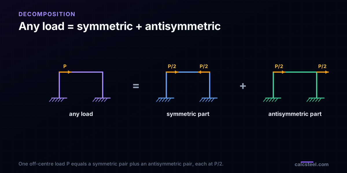
Here is the identity that turns one hard problem into two easy ones. Take any load on a symmetric structure. Add its mirror image, and you get a load that is perfectly symmetric. Subtract its mirror image, and you get one that is perfectly antisymmetric. Half of the sum plus half of the difference is the original load, exactly:
load = ½(load + mirror) + ½(load − mirror) = symmetric part + antisymmetric part.
A single force P sitting off to one side becomes P/2 mirrored to both sides (the symmetric part) plus P/2 on one side and −P/2 on the other (the antisymmetric part). A symmetric load reflects onto itself: gravity on a level beam, a pressure that is the same left and right, the self-weight of the frame. An antisymmetric load reflects onto its own negative: a sway push, a seismic inertia force, wind that suctions one slope while it presses the other.
Why bother splitting? Because a symmetric structure answers each part with a clean, predictable shape. Under the symmetric part it deflects symmetrically. Under the antisymmetric part it deflects antisymmetrically. Each of those shapes has a known behaviour on the axis, and that known behaviour is exactly what we replace the missing half with. Solve the two halves, add the answers, and you are back to the original load on the full structure, having never modeled more than one side.
The cut on the axis: what is zero, what is free
Everything rides on one section, the one the axis passes through. When the deflected shape is symmetric, that section cannot do certain things, and when it is antisymmetric it cannot do the opposite things. Those forbidden movements are exactly the restraints of the support we put there.
Under a symmetric load, the point on the axis cannot rotate (the mirrored slope would have to equal its own negative, so it is zero) and cannot slide sideways across the axis (same argument). It can move along the axis freely. The support that does precisely this, blocks rotation and the perpendicular slide, allows the along-axis movement, is a guided slider. Because a symmetric shape has zero slope on the axis, the internal shear at the cut is zero; the axial force and the bending moment survive and the slider carries them.
Under an antisymmetric load, it is the mirror image of that. The point on the axis cannot move along the axis (a symmetric displacement there would violate antisymmetry) but is free to rotate and to slide across. The support is a plain roller that blocks only the along-axis translation. Now the bending moment and the axial force at the cut are zero, and only the shear survives, which the roller carries. A member crossing an antisymmetric axis has an inflection point exactly on the axis, which is often the fastest way to see the whole result.
That is the entire cheat-sheet. Symmetric load: guided slider, shear is zero. Antisymmetric load: roller, moment and axial are zero. Swap the two and the model still runs, still looks reasonable, and is quietly wrong, which is why this is the one thing to get right.
A two-span beam, solved on one span
Start with the cleanest case, because it has a closed-form answer to check against. A continuous beam of two equal spans, L = 6 m each, sits on three supports and carries a symmetric uniform load of w = 20 kN/m over its whole length. The load mirrors about the centre support, so the response is symmetric, and the centre support sits right on the axis.
Model the whole beam in CalcSteel and the engine returns end reactions of R_A = R_C = 45 kN, a centre reaction of R_B = 150 kN, and a hogging moment over the centre of M_B = 90 kN·m. Those are the textbook numbers for a two-span beam: R = 3wL/8 = 45 kN at the ends, 5wL/4 = 150 kN in the middle, and M = wL²/8 = 90 kN·m over the support, with the peak sagging moment of 50.6 kN·m landing at 2.25 m into each span. Because the beam is prismatic, none of these depend on the section.
Now halve it. Keep one span, A to B. Support A stays a pin. At B the axis does two jobs at once: the real roller already stops the vertical movement, and symmetry stops the rotation and the sideways slide. All three in-plane freedoms are blocked, so B becomes a fixed end and the half-model is a single propped cantilever, pinned at A and fixed at B. Solve that one span and the engine gives R_A = 45 kN and M_B = 90 kN·m, the same numbers, from a model with 6 degrees of freedom instead of 9. The vertical reaction the fixed end reports, 75 kN, is exactly half of the 150 kN centre reaction, because the full centre support draws from both spans and the half-model only sees one. The full diagram is in the shear and bending moment guide; here the point is only that one span carried the whole answer.
A portal under gravity: the guided slider
Beams are gentle because the axis lands on a support. A frame is the real test, because the axis cuts through the middle of a beam that is carrying load. Take a fixed-base portal, 8 m span and 4 m columns, with a symmetric gravity load of w = 15 kN/m along the beam. The frame mirrors about its centre and so does the load, so the response is symmetric and the cut belongs at the beam midspan.
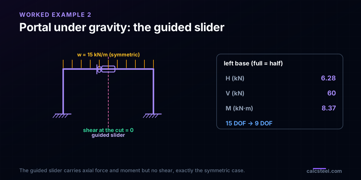
Following the cheat-sheet, the support there is a guided slider: it blocks the horizontal slide and the rotation, and lets the midspan drop vertically. Model the left half, one column and half the beam, with that slider on the cut. The engine reports the left base as a horizontal thrust of 6.28 kN, a vertical reaction of 60 kN, and a base moment of 8.37 kN·m. Run the full frame and the left base reads 6.28 kN, 60 kN and 8.37 kN·m, identical, while the beam moment at the eave comes out at 16.7 kN·m on both. The 60 kN is a good sanity check on its own: the total gravity load is 15 kN/m over 8 m, which is 120 kN, split evenly to 60 kN per base.
And the tell-tale of a symmetric response: the engine reports the beam shear at the cut as exactly zero. That is not luck, it is the definition of the symmetric case, and it is why the slider, which carries no shear, is the correct support. The half-model went from 15 degrees of freedom to 9 and lost nothing.
The same portal swaying: the roller
Keep the frame, change the load. Push the two eaves sideways with 30 kN each, in the same direction. That is a sway load, and a sway load is antisymmetric: its mirror image is the same push pointing the other way, which is its own negative. So the response is antisymmetric, and the cheat-sheet swaps the support at midspan from a slider to a plain roller, blocking only the vertical movement.
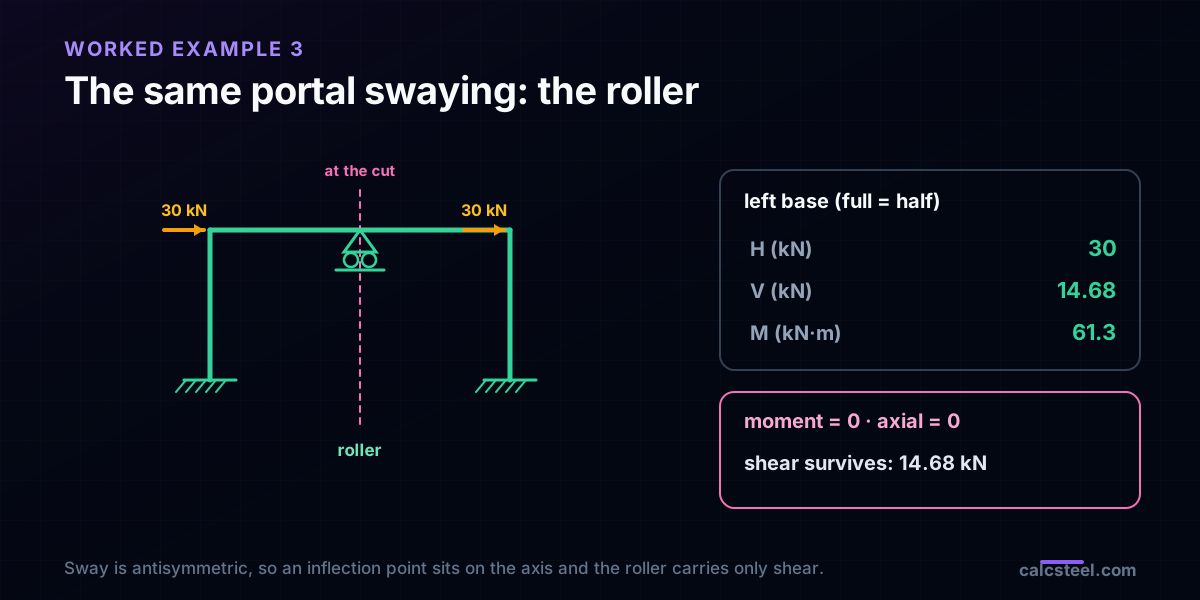
Model the left half with that roller and the single 30 kN push on its own eave. The engine gives a left base with a horizontal reaction of 30 kN, a vertical reaction of 14.68 kN, and a base moment of 61.3 kN·m. The full frame returns the same three numbers. What is striking is the cut itself: the beam bending moment there is zero and so is the beam axial force, while the shear is a healthy 14.68 kN. That is the antisymmetric signature, an inflection point sitting right on the axis, and it is why the roller, which carries shear but no moment and no axial, is the support the physics demands.
The vertical reactions are the other half of the story. Under pure sway the two column bases push and pull, one down and one up, a couple that resists the overturning. The half-model sees only its own side of that couple, 14.68 kN, and that is exactly what the full model reports on the left base. Same 9 degrees of freedom, same answer, opposite load type.
Decomposition in action: one push, two halves
The two portal runs above were pure cases. Real loads are rarely pure, so here is the payoff that ties it together. Push a single 40 kN force at the left eave only, nothing on the right. That load is neither symmetric nor antisymmetric, so on its own it does not fit either half-model. Split it. Half of it, mirrored, is a symmetric pair of 20 kN pointing toward the centre. Half of it is an antisymmetric pair of 20 kN both pushing the same way, a sway.
Solve the symmetric half with the slider and the 20 kN symmetric share, and the left eave drifts a mere 0.055 mm. Solve the antisymmetric half with the roller and the 20 kN sway share, and the same eave drifts 54.53 mm. Add them: 0.055 + 54.53 = 54.58 mm. Model the original one-sided 40 kN push on the full frame with no symmetry tricks at all, and the engine reports a drift of 54.58 mm. The base moments add the same way, 0.04 from the symmetric part plus 40.87 from the antisymmetric part gives 40.9 kN·m, exactly the full-model value.
Read the split and you learn something the full model hides: a one-sided push is almost entirely a sway problem. The symmetric part contributes a rounding error to the drift, and the antisymmetric part carries 99.9% of it. That is why lateral design lives or dies on the sway case, and it is the kind of insight the decomposition hands you for free while the black-box full-model answer keeps it hidden. For the serviceability side of a drift like this, the deflection limits guide sets the numbers a client actually checks.
The member that lies on the axis
So far the axis has cut across members: a beam at midspan, a support in the middle. Sometimes it runs straight down a member instead, a central column under the ridge of a symmetric frame, a king post in a truss, a central tie. That member belongs to both halves at once, and the half-model has to share it fairly.
The rule is simple: give the half-model half of that member. Halve its area and halve its moment of inertia, because the full member is split down the middle between the two sides. Under a symmetric load the shared member stays on the axis, takes axial force and, if it bends at all, bends symmetrically. Under an antisymmetric load the same member cannot take axial force at all, because an axial force on the axis would have to be symmetric while the response around it is antisymmetric; it works purely in bending and shear as the two sides sway past each other. Forgetting to halve a shared member is a common way to get a half-model that is close but not exact, stiffer than the real structure by whatever that central member contributes.
Why halve, when the solver does not care?
An honest objection: a modern solver eats the full portal in well under a millisecond, so who cares about nine degrees of freedom versus fifteen? The speed was the reason a century ago, when Hardy Cross and a slide rule made every degree of freedom expensive. It is not the reason now. The reasons now are about the human holding the model.
- It is a free error trap. A symmetric structure under a symmetric load must give a symmetric answer. If your full model reports different reactions left and right under gravity, you have a modeling mistake, a mismatched section, a support typed wrong, a node off by a millimetre. The symmetry you expected is the check that catches it.
- It is a hand-check you can trust. Halving turns an indeterminate frame into something you can verify by hand or against a closed form, exactly as the two-span beam collapsed to a propped cantilever with a known answer. A number you can reproduce two ways is a number you can defend.
- It shows you the load path. The decomposition told us a one-sided push is 99.9% sway. That understanding, not the raw drift, is what tells you where to put a brace or how the frame actually carries the load. The serviceability answer is only useful once you know which part of the load produced it.
- It scales to the cases that still hurt. The same idea runs a quarter of a double-symmetric building, or one slice of a cyclically symmetric tank, silo or dome, where the full model genuinely is expensive. Learn it on a portal and it pays off on the structure that does not fit in memory.
Where the half-model quietly lies
- The load is not symmetric. Patterned live load, wind that presses one slope and suctions the other, a crane on one runway: none of these reflect onto themselves. Do not force a single half-model on them, split them into a symmetric and an antisymmetric case first.
- Slider and roller swapped. Putting a roller where the load is symmetric, or a slider where it is antisymmetric, gives a model that runs and looks plausible and is wrong. The load type chooses the support, every time.
- The supports break the symmetry. A geometrically mirrored frame that is fixed on one side and pinned on the other is not symmetric. Neither is one with a settlement, a spring, or a released base on only one side. Symmetry has to hold in the supports too.
- A shared member left whole. A member sitting on the axis must enter the half-model at half its area and half its inertia. Leave it whole and the half-model is stiffer than the real structure.
- Assuming self-weight needs splitting. It does not. Gravity on a symmetric frame is already a symmetric load, so it goes straight into the symmetric half. Recognising which loads are already pure saves half the work.
Try it live on a symmetric portal
The fastest way to feel this is to build the symmetric portal and watch it answer the two load types differently. The calculator below is the CalcSteel portal-frame tool, free and with no login for the maths. Give it two equal columns, a beam across the top, and matching bases, then load it two ways. Put a uniform gravity load on the beam and read a symmetric result: equal base reactions, a bending diagram that mirrors, zero shear at midspan. Then push it sideways and watch the response flip to antisymmetric: the base moments grow, the bases form a push-pull couple, and the beam moment passes through zero at the centre.
Once you can see the two shapes, the half-model stops being a trick and becomes obvious: the slider belongs where the shear is already zero, the roller where the moment already is. From here the natural neighbours are the shear and bending moment guide, whose diagrams are what you are halving, and the three-hinged arch, another structure that a single well-placed release turns from hard into simple.
Diagrams plotted on the deformed-free frame geometry. N, V, M recovered from the element end-forces of the direct-stiffness solve (12 elements / member). Moment drawn offset to each member's centreline.
First-order STRENGTH screening at the governing section of the NBR 8800 (BR) ULS envelope (governing CB2): N,d = 73.9 kN, M,d = 109 kN·m. Member buckling and lateral-torsional buckling are NOT included — see the stability flags below and run the full verification in the 3D editor. Click a card to make that resistance code govern the ranking.
ULS load combinations — NBR 8800 (BR)
G + W superposed · 3 combinations| Combination | Factors | Utilization |
|---|---|---|
| CB1 | 1.4 G | 69% |
| CB2governs | 1.4 G + 1.4 W | 76% |
| CB3 | 1 G + 1.4 W | 57% |
Combinations generated by the CalcSteel combinations engine (the same v4 engine the 3D editor uses, 6 codes). Gravity is treated as a single permanent action G; the wind action W is the eaves load. Each combination's γ factors are applied by superposition to the isolated gravity and wind solves, then every section is screened — the worst point of the worst combination governs.
Stability screening (buckling caveats)
not in the strength checkScreening indicators only — assumed sway effective length (K = 1.5) and the full member length as the unbraced length (no intermediate purlin/girt restraint). The strength check above deliberately excludes these; the real member verification (effective lengths from the alignment chart / notional loads, χ and Cb reduction factors, purlin bracing) runs in the 3D editor.
Lightest sections that pass (NBR)
screened 974 profiles| Profile | Mass | Frame steel | Utilization | |
|---|---|---|---|---|
| VS 400x32 | 31.9 kg/m | 723 kg | 82% | |
| VS 350x33 | 33.2 kg/m | 752 kg | 86% | |
| VS 400x34 | 34.4 kg/m | 779 kg | 75% | |
| VS 350x35 | 35.1 kg/m | 795 kg | 80% | |
| VS 400x35 | 35.1 kg/m | 795 kg | 73% |
Try CalcSteel for free
Model, analyze and design steel structures in your browser. No install, no signup.
Open the 3D editor