Structural Bracing: the Braced versus Unbraced Criterion Behind the Code
Structural bracing is not judged member by member, it is judged at the whole frame. A brace has two jobs at once: complete the load path that carries the story shear down to the foundation, and add enough stiffness to hold the drift. Take one 6.0 m by 4.0 m bay and run it twice on the real CalcSteel engine. As a bare moment frame it drifts 254 mm, H/16, and each column eats 200 kN of moment. Add a single SHS 90x90x5 diagonal and the same steel drifts 3.3 mm, H/1195, the columns shed their bending to zero, and the diagonal carries the whole 100 kN shear as 120.2 kN of tension, exactly V divided by cosine theta. This guide derives that criterion from first principles and proves it end to end.
Key takeaways
- Structural bracing does two things a moment frame does the hard way: it turns the horizontal story shear into pure axial force in a diagonal (the load path, V divided by cos theta) and it makes the frame a non-sway frame, so the columns carry axial only and their effective length drops from a sway K near 2 to a braced K near 1.
- The worked bay proves it. The same HEB 160 columns and IPE 330 beam drift 254 mm (H/16, a serviceability failure) as a moment frame with 200 kN.m in each column; add one SHS 90x90x5 diagonal and drift collapses to 3.3 mm (H/1195) with the column moment gone. A 17 cm2 tube did what the bare frame could not.
- The brace force is statically determinate: the engine reads 120.18 kN in the diagonal against the hand value V/cos theta = 120.19 kN, a 0.01 percent match. The story shear of 100 kN becomes 120.2 kN of axial because the diagonal is inclined at 33.7 degrees.
- Stiffness is easy here, stability of the brace under reversal is what sizes it. In tension the tube is 22 percent used. But wind reverses, and as a single 7.211 m compression diagonal its slenderness is KL/r = 207, over the 200 limit, and it buckles at 61.5 kN, a 195 percent failure. Cross it into an X so the crossing halves the buckling length (KL/r = 104) and phi.Pn jumps to 241.7 kN, 50 percent used.
- Design the brace for the load path and the reversal, then design the beams, columns, collectors and connections for the brace capacity, not the elastic demand. A brace that is not connected to a real, stiff node is not a brace.
What structural bracing actually is
Structural bracing is the set of members that give a frame its sideways strength and stiffness. Gravity a frame handles naturally, beams and columns are already in line with it. Horizontal load is the problem: wind, earthquake, crane surge and notional out-of-plumb forces all push the floors sideways, and a bare beam-and-column grid with simple (pinned) connections has nothing to stop that push. It is a mechanism. Bracing is what closes it.
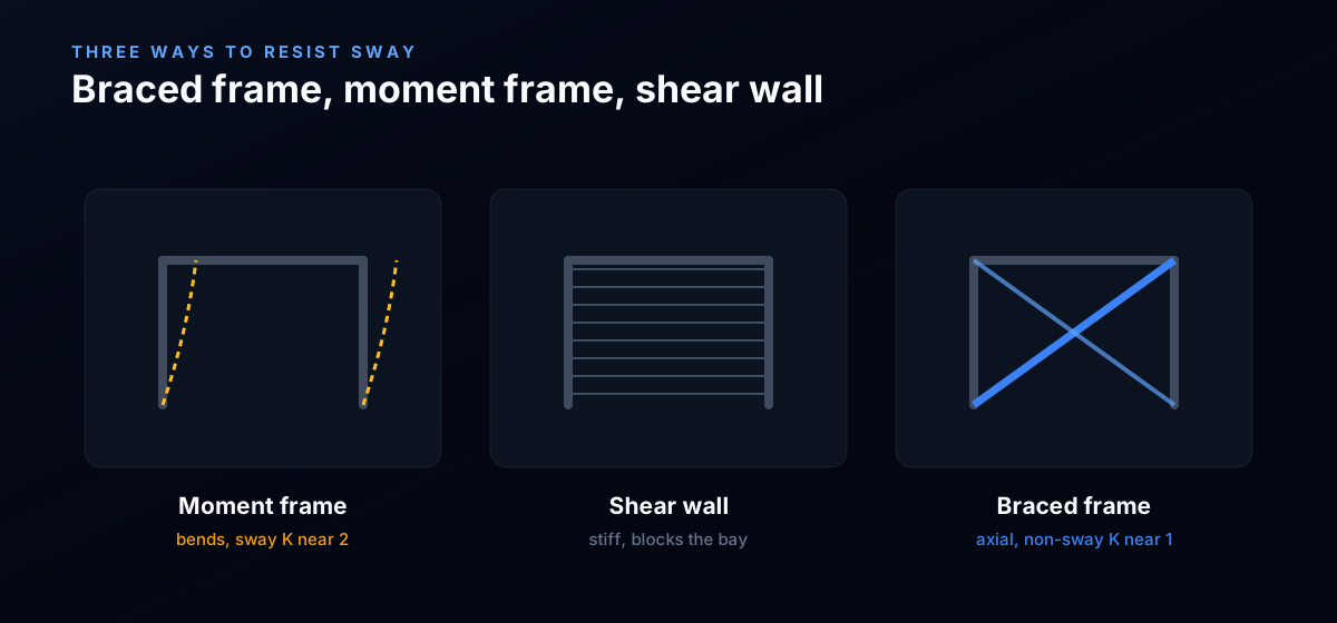
There are only three ways to resist that sideways push: bend the columns (a moment frame), fill a bay with a wall (a shear wall or infill), or triangulate a bay with diagonals (a braced frame). Diagonal bracing is the one this guide is about, and it is the most efficient of the three, because a diagonal resists the push in pure axial force instead of bending. Axial members are stiff and light; bending members are neither.
The whole subject comes down to a single, testable idea: a brace must complete a load path (a strength job) and it must be stiff enough to keep the drift inside the code limit (a serviceability job). Get both and the frame is braced. Miss either and you have a frame that either fails a check or, worse, sways enough to crack cladding and frighten occupants while every member still passes its own stress check. We will size a real brace against both criteria on the CalcSteel engine.
Braced frame, moment frame, shear wall: where bracing sits
Before sizing anything, place diagonal bracing among its alternatives, because the code treats them differently and so does the cost.
- Moment frame. No diagonals. The joints are rigid, and the columns and beams resist sway by bending. It leaves the bay open for doors and glass, but it is flexible and steel-hungry: you often pay for stiffness (drift), not strength.
- Shear wall or infill. A concrete core or a braced masonry panel. Very stiff, but it blocks the bay and ties the steel design to another trade.
- Braced frame. Diagonals triangulate the bay. Stiff, light and cheap, at the cost of a blocked bay line. This is where structural bracing lives: X (cross) bracing, single diagonals, chevron (inverted V) and K bracing, plus the eccentric and buckling-restrained variants used for seismic ductility.
The dividing line the code cares about is sway versus non-sway. A moment frame is a sway frame: its columns can lean, so their buckling (effective) length is long. A braced frame is a non-sway frame: the diagonals hold the joints in place, so the columns buckle over their true length. That single distinction, sidesway prevented or not, is the criterion behind half of what follows.
The load path: where the brace force comes from
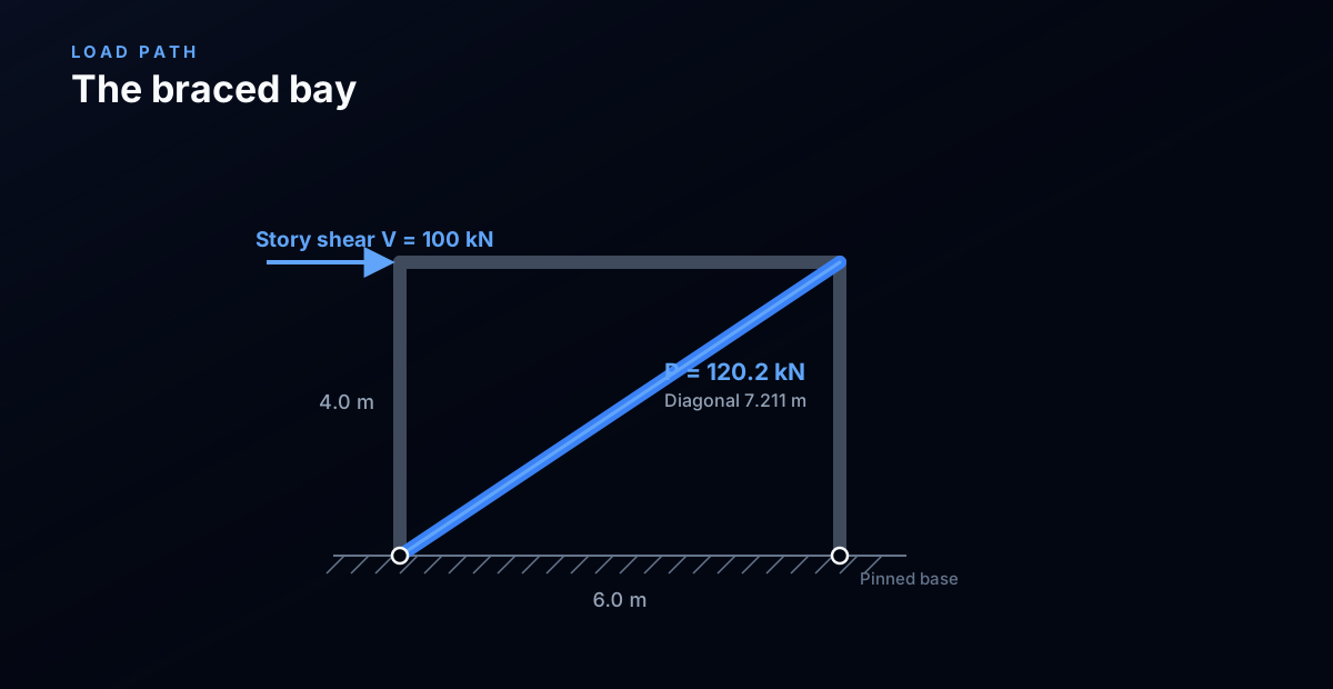
Start with statics, because the brace force is decided by geometry alone, not by stiffness. Push the top of the bay with a story shear V = 100 kN. In a braced bay with simple (pinned) beam-to-column connections, the columns are vertical two-force members: a vertical member cannot resist a horizontal push, so it carries none of the shear. The only member that can is the diagonal.
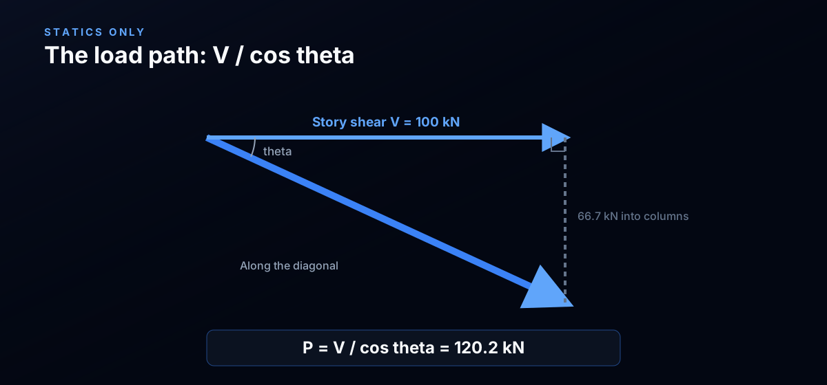
The diagonal runs from a base corner to the opposite top corner. With a bay 6.0 m wide and 4.0 m tall its length is the hypotenuse, √(6² + 4²) = 7.211 m, inclined at 33.69° from horizontal, so cos θ = 6 / 7.211 = 0.832. Only the horizontal component of the diagonal's axial force resists V, so:
P · cos θ = V → P = V / cos θ = 100 / 0.832 = 120.2 kN
That is the load path in one line: a 100 kN horizontal push becomes 120.2 kN of axial force in the diagonal, and its vertical component, P · sin θ = 66.7 kN, is delivered into the columns as extra axial. The flatter the brace, the larger P: at 20° the same shear would need 106 kN, at 45° only 141 kN over √2. Geometry sets the demand before any section is chosen, which is exactly why this number is the first thing to check by hand.
The criterion behind the code, from first principles
Codes do not phrase bracing as one rule, they phrase it as three demands that a brace has to meet at the same time. Read together they are the criterion:
- Strength, the load path. The brace and every element in the path (diagonal, its connections, the collector beams, the columns below) must carry the brace force P = V / cos θ. AISC 360 chapters D (tension) and E (compression), Eurocode 3 clause 6, and NBR 8800 all size the member for this axial force.
- Stiffness, the drift. The braced frame must not sway more than the serviceability limit, typically H/400 to H/500 under wind (ASCE 7 Appendix CC, AISC Design Guide 3). Drift protects cladding, partitions and comfort, and it is a limit no strength check contains.
- Stability, the effective length. Because bracing makes the frame non-sway, the columns it braces may be designed with a braced effective-length factor K near 1.0 instead of the sway value that runs from about 1.2 to well above 2. The brace itself must also survive load reversal, so its own compression buckling governs, not its tension yield.
The deep reason bracing works is the third point. A sway (moment) frame lets its column tops translate, and a column whose top can move sideways buckles at a fraction of the load of one whose top is held. Bracing holds that top. In the AISC alignment charts this is the jump from the sidesway-uninhibited nomograph (K ≥ 1) to the sidesway-inhibited one (K ≤ 1). Everything below is that abstract criterion turned into numbers.
What a brace must deliver: strength, stiffness, stability
Translate the three demands into the three checks an engineer actually runs on the diagonal.
Strength. In tension, φPn = 0.9 FyAg (AISC D2, gross-section yield). In compression, φPn = 0.9 FcrAg with Fcr from AISC E3, which collapses with slenderness. Both must exceed P = V / cos θ.
Stiffness. A single diagonal's contribution to lateral drift is Δ = P Ld / (E A cos² θ). This is what has to stay under H/400. Note it depends on area A, not on strength: a stronger steel grade does nothing for drift, only more area or a steeper brace does.
Stability and slenderness. Codes cap the slenderness of the diagonal: KL/r ≤ 200 for compression members and about 300 for tension-only members (AISC and Eurocode agree closely). This is the check that most often decides the section, because a diagonal long enough to cross a bay is naturally slender. For an X brace, the tension diagonal restrains the crossing point, so the compression diagonal buckles over half its length, which is the entire reason X bracing is so common. We derive that in the dedicated steel cross bracing guide.
Worked check, part 1: the same bay, braced versus unbraced
Here is the demonstration. One bay, 6.0 m by 4.0 m, pinned bases, HEB 160 columns and an IPE 330 beam, S355 steel, under a 100 kN story shear. We run it twice on the CalcSteel finite-element engine and read the eave drift and the column moment.
| Configuration | Eave drift | Drift ratio | H/400 = 10 mm | Column moment |
|---|---|---|---|---|
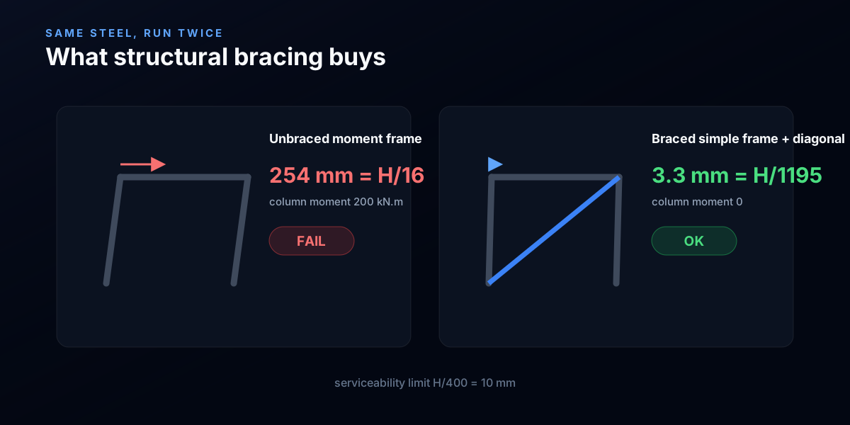
| Unbraced (moment frame, rigid knees) | 254 mm | H/16 | FAIL | 200 kN.m |
| Braced (simple frame + one diagonal) | 3.3 mm | H/1195 | OK | 0 kN.m |
The bare moment frame drifts 254 mm. That is H/16, seventy-six times over the H/400 serviceability limit, a frame no cladding would survive, and its columns are working in bending, 200 kN.m each. Add one SHS 90x90x5 diagonal, a 17 cm² tube weighing about 13 kg/m, and change nothing else, and the drift drops to 3.3 mm, H/1195. The column moment falls to zero: the diagonal now carries the shear as axial force, so the columns are pure struts again. A brace that weighs a fraction of one column took the frame from a gross serviceability failure to a check passed with a factor of thirty to spare. That is what structural bracing buys, and no amount of column upsizing in the moment frame is as efficient.
Worked check, part 2: the brace force from the engine
Now confirm the load path the statics predicted. In the braced model the engine reports the diagonal axial force as 120.18 kN. The hand value is V / cos θ = 100 / 0.832 = 120.19 kN. The two agree to 0.01 percent, which is the signature of a determinate load path: with simple connections the diagonal carries the entire story shear and nothing leaks into column bending.
The engine also confirms the vertical share. The diagonal's 66.7 kN vertical component appears as added axial in the columns, and the beam carries 50 kN of axial as it drags the far column into the brace. None of this is guesswork: it is equilibrium, and it is why the very first thing to do on any brace is to read P = V / cos θ off the geometry and sanity-check whatever the model returns against it. If the model disagrees with V / cos θ by more than a percent or two, the connections are not as pinned as the drawing claims, and frame action is stealing shear.
See it yourself: the live frame calculator
The whole braced-versus-unbraced story is one experiment you can run yourself. In the portal frame calculator below, build the 6.0 m by 4.0 m bay with HEB 160 columns and apply the 100 kN lateral load, then read the drift, that is the unbraced case, H/16. Now shrink the columns and watch the moment frame get worse, or stiffen them and watch how much steel it costs to reach H/400 by bending alone. Compare that against the 3.3 mm a single small diagonal delivered above.
It is the same finite-element engine used for the worked numbers, free, and with no login for the math.
Diagrams plotted on the deformed-free frame geometry. N, V, M recovered from the element end-forces of the direct-stiffness solve (12 elements / member). Moment drawn offset to each member's centreline.
First-order STRENGTH screening at the governing section of the NBR 8800 (BR) ULS envelope (governing CB2): N,d = 73.9 kN, M,d = 109 kN·m. Member buckling and lateral-torsional buckling are NOT included — see the stability flags below and run the full verification in the 3D editor. Click a card to make that resistance code govern the ranking.
ULS load combinations — NBR 8800 (BR)
G + W superposed · 3 combinations| Combination | Factors | Utilization |
|---|---|---|
| CB1 | 1.4 G | 69% |
| CB2governs | 1.4 G + 1.4 W | 76% |
| CB3 | 1 G + 1.4 W | 57% |
Combinations generated by the CalcSteel combinations engine (the same v4 engine the 3D editor uses, 6 codes). Gravity is treated as a single permanent action G; the wind action W is the eaves load. Each combination's γ factors are applied by superposition to the isolated gravity and wind solves, then every section is screened — the worst point of the worst combination governs.
Stability screening (buckling caveats)
not in the strength checkScreening indicators only — assumed sway effective length (K = 1.5) and the full member length as the unbraced length (no intermediate purlin/girt restraint). The strength check above deliberately excludes these; the real member verification (effective lengths from the alignment chart / notional loads, χ and Cb reduction factors, purlin bracing) runs in the 3D editor.
Lightest sections that pass (NBR)
screened 974 profiles| Profile | Mass | Frame steel | Utilization | |
|---|---|---|---|---|
| VS 400x32 | 31.9 kg/m | 723 kg | 82% | |
| VS 350x33 | 33.2 kg/m | 752 kg | 86% | |
| VS 400x34 | 34.4 kg/m | 779 kg | 75% | |
| VS 350x35 | 35.1 kg/m | 795 kg | 80% | |
| VS 400x35 | 35.1 kg/m | 795 kg | 73% |
Worked check, part 3: sizing the diagonal, and what governs
Stiffness was easy, the tube delivered H/1195. So what sizes the brace? Strength under reversal. Take the demand P = 120.2 kN and check the SHS 90x90x5 (A = 17 cm², r = 34.8 mm, S355) three ways.
| Check | Slenderness KL/r | φPn | Utilisation | Verdict |
|---|---|---|---|---|
| Tension (D2 yield) | n/a | 543.1 kN | 22 % | OK, huge margin |
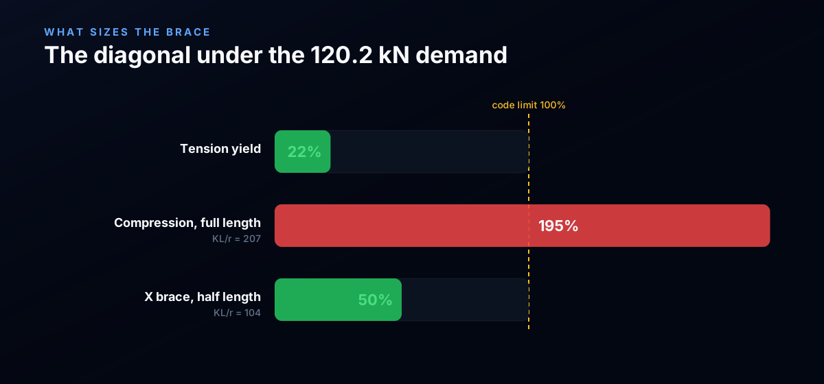
| Compression, single full-length diagonal | 207 | 61.5 kN | 195 % | FAIL, buckles |
| Compression, X brace (KL = 0.5 L) | 104 | 241.7 kN | 50 % | OK |
Read top to bottom, this is the lesson of structural bracing. In tension the tube is barely stressed, 22 percent, steel is enormously strong in tension. But wind blows both ways, so the diagonal must also work in compression, and as a single 7.211 m diagonal its slenderness is KL/r = 207, past the 200 code limit, and it buckles at 61.5 kN, a 195 percent failure. The fix is the criterion the code enforces: make it an X, so the tension diagonal braces the crossing point and the compression diagonal buckles over half its length. Slenderness drops to 104 and φPn jumps to 241.7 kN, 50 percent used. Same tube, same load, different buckling length. The brace was never sized by its tensile strength or by drift, it was sized by its compression stability.
What bracing does to the column: from sway to braced
The drift and the vanished column moment are two faces of the same effect. In the unbraced moment frame the column top can translate, so the column is a sway member: its effective-length factor K runs from 1.2 to over 2, and it carries 200 kN.m of bending as it leans. In the braced frame the diagonal holds the top in place, so the column becomes a non-sway member, K near 1.0, with no lateral moment at all. Its axial capacity rises and its demand simplifies.
That is why bracing is worth so much more than its own weight. It does not just carry the wind, it shortens the buckling length of every column it holds and strips the sway moment out of them. A slender column that would need to be heavy to survive as a sway member can be light once a brace makes it non-sway. The alignment-chart jump from sidesway-uninhibited to sidesway-inhibited, and the connected topics of the effective length K factor and drift limits, are the code machinery for exactly this trade.
Common mistakes and FAQ
Sizing the brace for tension only and forgetting reversal. The tension check passed at 22 percent. If you stop there and the wind reverses, the same diagonal is in compression and buckles. Either design a tension-only pair (an X, with a diagonal for each direction) or check the single diagonal in compression.
Connecting to the elastic demand, not the capacity. The diagonal, its gusset, the bolts or welds, the collector beam and the columns below all carry the brace force. Codes ask you to design the load path for the brace's expected strength (in seismic work, its capacity), not merely the 120 kN elastic demand, so the brace yields before its connections break.
Assuming the brace point is real. A brace is only as good as the node it connects to. A diagonal framing into a flexible beam mid-span, or a connection that slips before it bears, does not hold the frame: the drift comes back and the effective length grows. The related brace stiffness and strength requirement (AISC Appendix 6) is the code's answer to this: a brace must deliver a minimum stiffness, not just a minimum force.
Out-of-plane buckling. The compression diagonal can buckle out of the plane of the frame, where nothing braces its midpoint. For a real X, the out-of-plane length is often the full diagonal even when the in-plane length is halved. Check both planes.
Flat is expensive. A very shallow brace (small angle to horizontal) needs a large axial force for the same shear, and it drifts more. Where headroom allows, a steeper brace is a lighter brace.
Key takeaways
- Bracing has two jobs, judged at the frame: complete the load path (strength, P = V / cos θ) and hold the drift (stiffness, H/400 to H/500). A brace that passes one and fails the other is not adequate.
- The load path is geometry. On the worked bay, 100 kN of story shear became 120.2 kN of axial, and the engine matched V / cos θ to 0.01 percent. Check this by hand before you trust any model.
- Bracing is astonishingly efficient. One 17 cm² diagonal took the bay from 254 mm of drift (H/16, fail) to 3.3 mm (H/1195), a 76 times reduction, and removed 200 kN.m from each column.
- Compression stability sizes the brace, not tension or drift. The tube was 22 percent used in tension but failed at 195 percent as a full-length compression diagonal (KL/r = 207); crossed into an X (KL/r = 104) it passed at 50 percent.
- Bracing makes columns non-sway. It drops their effective length from a sway K near 2 to a braced K near 1 and strips out their sway moment, which is why the brace is worth far more than its weight.
Sources
- 1.AISC 360-16, Specification for Structural Steel Buildings (Ch. C stability, D tension, E compression, App. 6 bracing)
- 2.AISC Design Guide 3, Serviceability Design Considerations (drift limits)
- 3.ASCE 7, Minimum Design Loads (Appendix CC, serviceability drift)
- 4.Eurocode 3 (EN 1993-1-1), buckling and bracing, with EN 1990 serviceability
- 5.Eurocode 8 (EN 1998-1), seismic design of braced frames
- 6.ABNT NBR 8800, Projeto de estruturas de aco e de estruturas mistas de aco e concreto
Try CalcSteel for free
Model, analyze and design steel structures in your browser. No install, no signup.
Open the 3D editor