Drift limits and serviceability: the criterion that sizes the frame before strength does
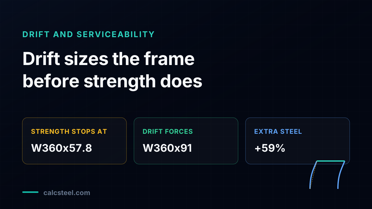
On a lateral frame, the column you can justify on strength is rarely the column you build. Strength alone stops at a W360x57.8: its interaction ratio is 0.95, just under the limit, and the code says it passes. Then you check the sway, and the drift criterion forces you all the way up to a W360x91. That is three sizes heavier and 59% more column steel, bought entirely for stiffness. This article runs both checks on the real CalcSteel engine and shows, member by member, how serviceability decides the frame first.
Key takeaways
- Sizing this portal frame on strength alone stops at W360x57.8, with an AISC H1.1 interaction ratio of 0.95, just under 1.0.
- That same section drifts 21.2 mm under the 0.7W service wind, which is H/283, well over the H/400 = 15.0 mm limit: strength passes, drift fails.
- Drift is only satisfied at W360x91, with 14.9 mm = H/402, three sizes heavier than the strength pick.
- The final W360x91 runs at an interaction ratio of only 0.66, so 34% of its strength capacity is never called on.
- Going from 57.5 to 91.5 kg/m is +59% column steel, paid entirely for stiffness and not for capacity.
The check that sizes the frame first
Most design workflows treat strength as the headline and serviceability as the footnote. You size the member so the factored loads do not exceed its factored resistance, you confirm the deflections look reasonable, and you move on. On a lateral frame that order is often backwards. The check that actually decides the column is not a stress check at all. It is the drift limit, a serviceability criterion, and it can force a member two or three sizes above what strength alone would accept.
The thesis of this article is simple and, once you have seen it happen, hard to unsee: on many moment frames, serviceability sizes the frame before strength does. The strength check passes on a lighter section, but the frame sways too far to be acceptable, so you keep climbing the table for stiffness you are not allowed to skip. The extra weight buys no additional safety against collapse. It buys a building that does not crack its cladding, rattle its partitions, or feel alarming to the people inside.
We will prove it on one worked frame, a single-story pinned-base portal, run end to end on the CalcSteel finite element engine. We will size the column on AISC 360 Chapter H interaction first, then apply the serviceability wind and read the real drift. You will watch the strength check pass while the drift check fails, and you will see exactly how far up the W360 family you have to go before both are satisfied. The numbers are engine-checked, and the engine itself is calibrated against a closed-form solution so you can trust them.
Drift is a displacement, not a stress
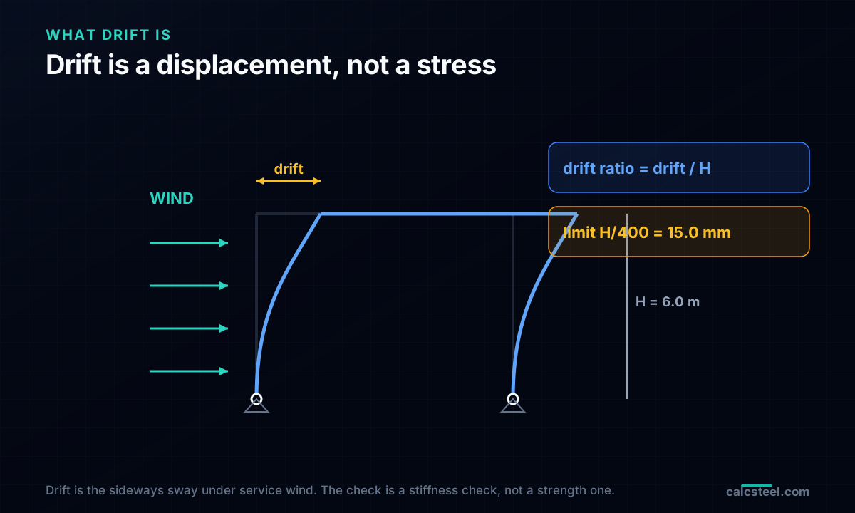
Lateral drift is the horizontal displacement of a structure under lateral load. On the portal frame in this article, it is how far the eaves move sideways when the wind pushes on the building. Story drift is the relative horizontal movement between the top and bottom of a single story, which on a one-story frame is simply the eave displacement measured from the fixed base. The drift ratio is that displacement divided by the height over which it occurred, and it is the number engineers actually judge against, because it normalizes movement to the height of the frame.
The critical thing to understand is that drift is a displacement, not a stress. A strength check asks whether a member is close to yielding, buckling, or rupturing, and it compares a demand to a resistance in units of force or moment. A drift check asks a completely different question: how much does the frame move, and is that movement tolerable for the things attached to it? No member stress appears in the calculation. You compute a deflection, you divide by a height, and you compare the result to a limiting ratio.
That places drift squarely among the serviceability limit states. A serviceability limit state is a condition that makes a structure unfit for normal use without threatening its safety: excessive deflection, vibration, cracking of attached finishes, or permanent deformation under service loads. The frame does not fall down when it drifts too far. It simply performs badly. That distinction, safety versus performance, is the reason the drift check is governed by judgment rather than by a code-mandated number, which is the subject of the next section.
Why the code sets no number
Here is a fact that surprises many engineers the first time they go looking for it: AISC 360 sets no numerical drift limit. Chapter L, the serviceability chapter, tells you that drift must be checked and that it belongs to serviceability, but it does not hand you an allowable value. There is no H/400, no H/500, no code floor. The specification states the principle and leaves the number to you.
This is deliberate, and it follows from what drift protects. Strength is about not failing, and failure is a universal condition, so the code mandates strength with load factors, resistance factors, and hard limits that no engineer may relax. Serviceability is about performance, and performance is contextual. A warehouse with metal siding tolerates far more movement than an office tower clad in brittle stone panels. The acceptable drift depends on the cladding, the partitions, the finishes, the occupancy, and the owner's expectations. A single code number could not serve all of them, so the code declines to impose one.
The number therefore comes from the engineer and the owner, guided by industry references rather than mandate. AISC Design Guide 3, Serviceability Design Considerations for Steel Buildings, collects the ratios the profession has converged on. ASCE 7 Appendix CC, Serviceability Considerations, provides the framework and the reduced load levels. These are recommendations and commentary, not enforceable minimums. The contrast is worth stating plainly: strength has resistance factors and a code floor you cannot go below, while drift has neither. You choose the limit, you document it, and you own the consequences of the choice.
The limits, and what each one protects
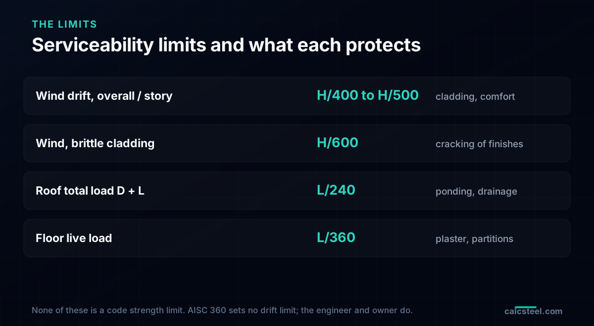
Although the code sets no number, the profession uses a well-worn set of ratios. For lateral wind drift, the common overall and story limits run from H/400 to H/500, where H is the height over which the drift is measured. Where the cladding is brittle, stone, masonry, or large glazing that cannot accommodate movement, the limit tightens to about H/600. These are the numbers that decide moment frames, and they are the reason a lateral frame so often ends up governed by stiffness.
Vertical deflection carries its own ratios. Roof members under dead plus live load are commonly held to L/240, where L is the span. Floor members under live load are held to L/360, a tighter limit because floors carry people, finishes, and expectations of a level surface. Each of these ratios exists to protect a specific thing, and it helps to name what:
Wind drift at H/400 to H/500 protects cladding and partitions from the racking movement that cracks joints and jams doors. The tighter H/600 protects brittle cladding that shatters rather than flexes. Roof deflection at L/240 protects drainage, keeping the roof from sagging into a low spot where water ponds, then adds weight, then sags further. Floor deflection at L/360 protects finishes and occupant comfort, keeping tile and plaster from cracking and keeping the floor from feeling springy underfoot. Every one of these is a choice matched to consequence, not a code strength limit. Pick the wrong one and you either overbuild or you deliver a building that performs badly while being perfectly safe.
Service loads carry no safety factor
The drift check is run at serviceability load levels, and this is where a great many drift calculations quietly go wrong. Serviceability asks how the structure behaves in normal use, so it uses unfactored loads. There is no load factor multiplying the demand up, and there is no resistance factor dividing the capacity down, because there is no capacity in the calculation at all. You are computing a real displacement under a realistic load and comparing it to a comfort limit.
For wind, serviceability uses a lower wind than strength does. ASCE 7 Appendix CC recommends checking drift against a wind with a 10-year mean recurrence interval, a far more frequent and therefore milder event than the design-level wind used for strength. In practice this is captured by the 0.7W combination: you take the strength-level nominal wind and multiply it by 0.7 to approximate the 10-year serviceability wind. In the worked frame, the nominal strength-level story shear is 20 kN, so the serviceability drift wind is 0.7 times 20, which is 14 kN. That is the load the drift check actually sees.
Why should the drift wind differ from the strength wind at all? Because they answer different questions. Strength asks whether the frame survives the rare, violent storm that might occur once in the building's life, so it uses a severe wind amplified by a load factor for safety against collapse. Serviceability asks whether the frame behaves acceptably in the ordinary windy day that happens several times a year, so it uses a mild wind at its real magnitude. Safety and performance are simply not the same question, and answering one with the other's load level is the most common way to get drift wrong. Use the factored wind for drift and you will size for a storm that does not govern comfort. Use the strength load combinations for a serviceability check and the whole exercise is meaningless.
One bay, two checks, the same wind
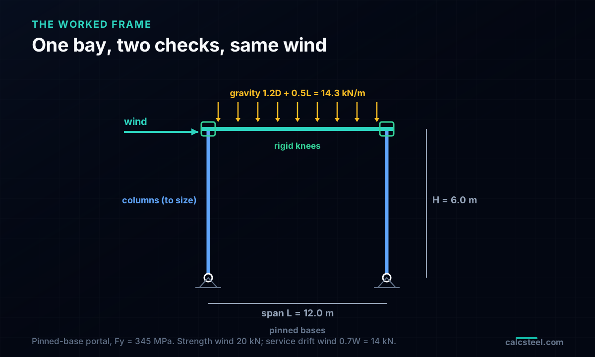
The worked frame is a single-story pinned-base portal moment frame, the standard low-rise lateral system. Two columns stand H = 6.0 m tall, spanning L = 12.0 m, joined at the top by a rafter through rigid moment connections at the knees. The column bases are pinned, which is the common and economical detail: a pinned base needs no large anchor-bolt moment connection and no thick base plate, but it makes the frame more flexible laterally, because all the lateral stiffness has to come from the columns bending in a guided-cantilever pattern. That flexibility is exactly why drift so often governs this system.
The steel is A572 Grade 50, equivalently A992, with a yield stress Fy = 345 MPa and a modulus of elasticity E = 200 GPa. The rafter is a stiff W530x82-class girder with Ix = 47,118 cm4, held fixed as the background of the study so that the column is the only variable. Gravity loads on the rafter are dead D = 9.0 kN/m and roof live L = 7.0 kN/m. The nominal strength-level wind is a story shear W = 20 kN applied at the eaves.
Two checks act on this one frame, and they use two different combinations. The strength check uses 1.2D + 1.0W + 0.5L, which puts a factored gravity load of 14.3 kN/m on the rafter along with the 20 kN wind, and it is evaluated as an AISC 360 Chapter H interaction on the leeward column. The drift check uses 0.7W only, which is the 14 kN service wind. Gravity is absent from the drift combination for a clean structural reason: a symmetric frame under symmetric gravity does not sway, because the two columns lean equally and the lateral movements cancel. Drift is a wind-only, essentially linear response here. We now run both checks on the real engine.
Sizing the column on strength
Start the way most engineers start, by sizing the column on strength. The governing combination is 1.2D + 1.0W + 0.5L, which loads the rafter at 14.3 kN/m and applies the 20 kN wind at the eaves. The leeward column carries the worst combination of axial force and bending moment, so it is the one to check. The measure is the AISC 360 Chapter H1.1 interaction ratio, the unity check that combines axial and flexural demand into a single number that must stay at or below 1.0.
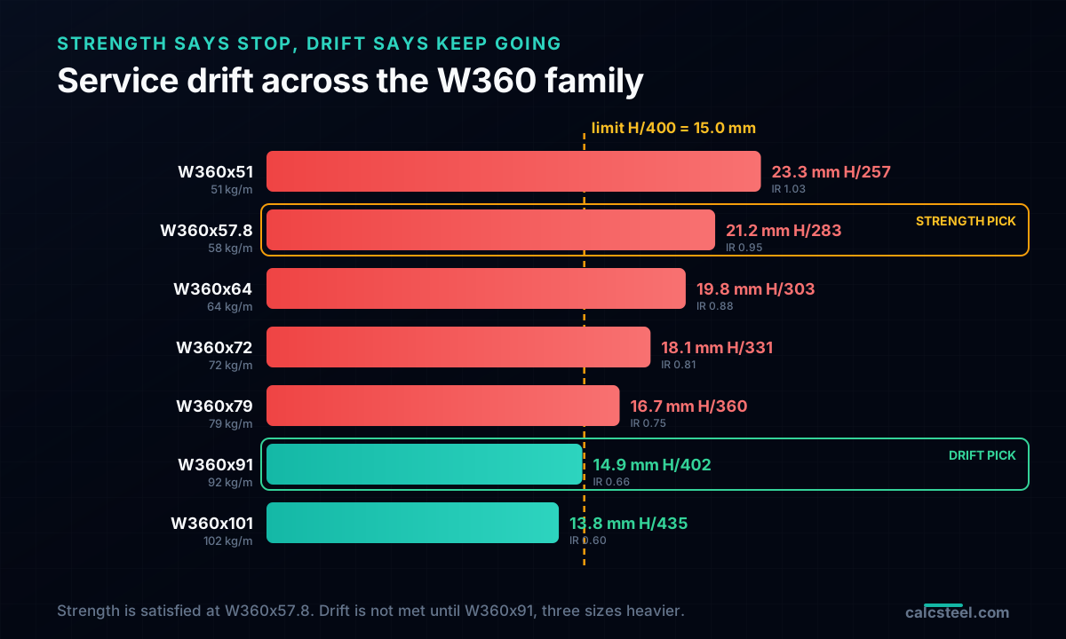
Climb the W360 family from the bottom. The W360x51, with Ix = 14,030 cm4 and a mass of 51.4 kg/m, returns an interaction ratio of 1.03. That is over 1.0, so it fails strength. Step up one size to the W360x57.8, with Ix = 15,951 cm4 and a mass of 57.5 kg/m. Its interaction ratio is 0.95, just under 1.0. It passes. It has a small but real margin, and by the logic of strength design it is the correct, efficient answer.
If strength were the only criterion, the design would be finished right here. You would specify the W360x57.8 at 57.5 kg/m, note the interaction ratio of 0.95, and record a member working near its economical limit with a sensible margin to spare. Every strength provision in the specification is satisfied. The temptation to stop is strong, because on a gravity member you would in fact be done. But this is a lateral frame, and there is a second question the strength check never asked.
Now check the drift
Take the same W360x57.8, the section that just passed strength, and subject it to the serviceability wind. The drift combination is 0.7W, the 14 kN service wind, applied at the eaves with no load factor. The engine returns an eave drift of 21.2 mm. Divide that by the 6.0 m height and the drift ratio is H/283.
The limit for this frame is H/400, which at H = 6.0 m works out to exactly 15.0 mm. The frame moved 21.2 mm, which is H/283. That is not a marginal miss. The frame is drifting roughly 40% more than the criterion allows. The strength check passed comfortably, and the drift check failed decisively, on the very same member under the very same wind, differing only in whether the load was factored and whether the question was about stress or movement.
Before trusting that 21.2 mm, it is fair to ask whether the engine can be believed, and here the calibration matters. A pinned-base portal with a near-rigid beam should sway according to the closed-form guided-cantilever expression, in which two columns each contribute a lateral stiffness of 6EI/H^3. Run that closed form and it gives 17.961 mm for the calibration case; the finite element engine returns 18.012 mm for the same case. That is a difference of 0.28%, which is finite element discretization noise against an exact hand solution. The engine is telling the truth. The W360x57.8 really does drift past the limit, and strength design has led you to a member that cannot be built as-is.
Drift keeps you climbing the table
Once drift fails, the only remedy is a stiffer column, which means climbing the table. Watch what happens to both checks as the section grows. The W360x64, Ix = 17,480 cm4, drifts 19.79 mm at H/303 with an interaction ratio of 0.88. The W360x72, Ix = 19,759 cm4, drifts 18.13 mm at H/331 with IR 0.81. The W360x79, Ix = 22,302 cm4, drifts 16.67 mm at H/360 with IR 0.75. Every one of these passes strength with ever-increasing margin, and every one of them still fails drift, because H/360 is still short of the H/400 limit.
The drift line is finally crossed at the W360x91, Ix = 26,403 cm4, which drifts 14.91 mm. That is H/402, just inside the H/400 = 15.0 mm limit. This is the section the frame actually needs. The next size up, the W360x101 with Ix = 29,858 cm4, drifts 13.80 mm at H/435 and passes both checks with room to spare, but it is heavier than necessary; the W360x91 is the lightest section that satisfies drift.
Lay the two checks side by side and the story is unmistakable. Strength was satisfied at the W360x57.8 and stayed satisfied all the way up, its interaction ratio falling from 0.95 to 0.66 as the section grew. Drift was violated at the W360x57.8 and stayed violated through four consecutive sizes, its ratio improving from H/283 to H/402 only at the W360x91. The member is dictated not by strength but by the drift criterion. From H/283 to H/402, the entire climb up the table was driven by stiffness, and strength had nothing to say about any of it.
The price of stiffness
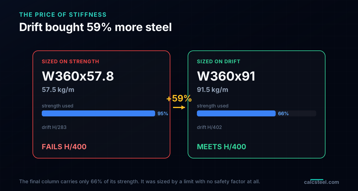
Now count the cost. The strength pick was the W360x57.8 at 57.5 kg/m. The drift pick is the W360x91 at 91.5 kg/m. That is an increase of +59% column steel, and every kilogram of it was bought for stiffness, not for capacity. The frame was never in danger of failing at 57.5 kg/m. It was in danger of moving too much, and the only cure for movement is a stiffer, and therefore heavier, member.
Look at what that stiffness does to the strength utilization. The W360x91 carries the factored loads at an interaction ratio of just 0.66. It is using 66% of its strength capacity, which means 34% of its capacity is never called on. A third of the member's strength sits idle for the entire life of the building. On a purely strength-driven member that would be a design error, an obviously oversized section. On this frame it is not an error at all. It is the unavoidable price of meeting the drift criterion.
This is the concrete meaning of the thesis. Serviceability is not a soft check you glance at after the real work is done. On a moment frame it is frequently the governing check, the one that sets the member size and the tonnage and the cost, while the strength check rides along with a comfortable and growing margin. If you size on strength and then bolt on a drift check as an afterthought, you will be surprised by a 59% weight penalty at the worst possible moment. Size for both from the start, and expect drift to win.
Run the drift check yourself
You do not have to take the numbers on faith. Reproduce them in the CalcSteel portal-frame calculator, which mounts right here. Build the bay exactly as described: H = 6.0 m columns, a 12.0 m span, pinned bases, rigid knees, and the stiff W530x82-class rafter as the background. Assign the column a section from the W360 family and set the steel to A992, Fy = 345 MPa, E = 200 GPa.
Then run the two checks separately. For strength, apply 1.2D + 1.0W + 0.5L and read the Chapter H interaction ratio on the leeward column. For drift, apply the service wind alone, 0.7W = 14 kN at the eaves, and read the eave displacement. Divide that displacement by the 6.0 m height and compare the ratio to H/400 = 15.0 mm. Start at the W360x57.8 to watch strength pass and drift fail, then step up through the family until the drift ratio finally drops below the limit at the W360x91. The calculator will land on the same answer the engine did.
Diagrams plotted on the deformed-free frame geometry. N, V, M recovered from the element end-forces of the direct-stiffness solve (12 elements / member). Moment drawn offset to each member's centreline.
First-order STRENGTH screening at the governing section of the NBR 8800 (BR) ULS envelope (governing CB2): N,d = 73.9 kN, M,d = 109 kN·m. Member buckling and lateral-torsional buckling are NOT included — see the stability flags below and run the full verification in the 3D editor. Click a card to make that resistance code govern the ranking.
ULS load combinations — NBR 8800 (BR)
G + W superposed · 3 combinations| Combination | Factors | Utilization |
|---|---|---|
| CB1 | 1.4 G | 69% |
| CB2governs | 1.4 G + 1.4 W | 76% |
| CB3 | 1 G + 1.4 W | 57% |
Combinations generated by the CalcSteel combinations engine (the same v4 engine the 3D editor uses, 6 codes). Gravity is treated as a single permanent action G; the wind action W is the eaves load. Each combination's γ factors are applied by superposition to the isolated gravity and wind solves, then every section is screened — the worst point of the worst combination governs.
Stability screening (buckling caveats)
not in the strength checkScreening indicators only — assumed sway effective length (K = 1.5) and the full member length as the unbraced length (no intermediate purlin/girt restraint). The strength check above deliberately excludes these; the real member verification (effective lengths from the alignment chart / notional loads, χ and Cb reduction factors, purlin bracing) runs in the 3D editor.
Lightest sections that pass (NBR)
screened 974 profiles| Profile | Mass | Frame steel | Utilization | |
|---|---|---|---|---|
| VS 400x32 | 31.9 kg/m | 723 kg | 82% | |
| VS 350x33 | 33.2 kg/m | 752 kg | 86% | |
| VS 400x34 | 34.4 kg/m | 779 kg | 75% | |
| VS 350x35 | 35.1 kg/m | 795 kg | 80% | |
| VS 400x35 | 35.1 kg/m | 795 kg | 73% |
Drift feeds stability (P-Delta)
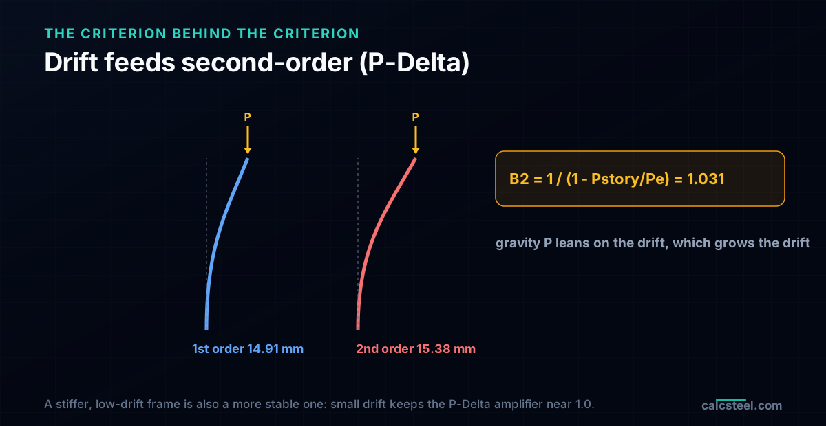
Drift and stability are not two topics. They are one. When a frame drifts sideways, the gravity load it carries is now acting on a leaning structure, and that gravity times the sideways offset creates an additional overturning moment, which produces additional drift, which adds more moment. This is the P-Delta effect, and AISC 360 Appendix 8 captures it for a story with the amplifier B2.
Put the drift pick through it. The story gravity load leaning on the frame is 172 kN, and the story elastic buckling strength is roughly 5634 kN. The amplifier is B2 = 1 / (1 minus 172/5634), which equals 1.031. Applied to the first-order drift, that nudges the 14.91 mm up to 15.38 mm at second order. The amplification is small here precisely because the frame is stiff and the drift is small: the ratio of gravity to buckling load stays low, so B2 stays close to 1.0.
That is the deeper reward for controlling drift. A low-drift frame is also a more stable frame. The same stiffness that keeps the eaves from moving too far also keeps the P-Delta amplifier near unity, which keeps the second-order moments close to the first-order ones and keeps the structure comfortably away from its buckling limit. Had you tried to build the flexible W360x57.8, you would have faced not only a serviceability failure but a larger stability amplification on top of it. Drift control and stability control are the same discipline, and paying for stiffness buys you both.
How to run the check, and what usually goes wrong
A practical procedure, in the order that avoids surprises. First, use service loads, not factored loads. Drift is checked at serviceability levels, which for wind means the 0.7W combination approximating the 10-year event, with no load factor and no resistance factor. Second, pick the right limit for the cladding. Use H/400 to H/500 for ordinary construction, tighten to H/600 for brittle cladding, and document the choice, because the code will not make it for you. Third, check story drift, not just roof drift. On a multi-story frame the roof displacement can look acceptable while an individual story racks badly, and it is the story drift that cracks that story's partitions.
Fourth, remember what kind of system you are sizing. A moment frame is inherently flexible, because it resists lateral load through bending, and that is why drift so often governs it. If drift dominates your design and the weight penalty hurts, the honest answer may not be a heavier moment frame at all. A braced frame or a shear wall resists lateral load through axial action and is far stiffer per kilogram, so it is frequently the better lateral system when serviceability is the binding constraint. Fifth, do the checks in the productive order: size for drift first, then confirm strength. On a lateral frame drift usually wins, so leading with it saves you from sizing on strength and then discovering the 59% penalty.
The common mistakes are the mirror image of these rules. Engineers use factored loads for the drift check, sizing for a storm that never governs comfort and overbuilding as a result. They forget that drift has no safety factor and no code number, either treating it as an enforceable minimum it is not or skipping it because the code did not demand it. And they ignore P-Delta, checking first-order drift only and missing the second-order amplification that a flexible frame makes worse. Get the load level right, get the limit right, check the right drift, and confirm stability, and the serviceability check will size the frame honestly, before strength ever gets a vote.
Sources
- 1.AISC 360-22, Specification for Structural Steel Buildings (Chapter L Serviceability; Appendix 8 approximate second-order analysis, B2)
- 2.AISC Design Guide 3, Serviceability Design Considerations for Steel Buildings (drift and deflection limits)
- 3.ASCE/SEI 7, Minimum Design Loads, Appendix CC Serviceability Considerations (drift, the 0.7W combination, 10-year wind)
- 4.Salmon, Johnson and Malhas, Steel Structures: Design and Behavior (deflection and serviceability, drift of frames)
Try CalcSteel for free
Model, analyze and design steel structures in your browser. No install, no signup.
Open the 3D editor