Double Integrals: The Moment of Inertia of a Built-Up Plate Girder from Scratch

The double integral you met in Calculus II is not a topic you close the book on after the exam. It is the exact definition of the number that decides how stiff a beam is: the moment of inertia is the double integral of y squared over the area of the cross-section, I = the double integral of y² dA. This guide sets that integral up from scratch, evaluates it by hand over the three rectangles of a welded plate girder, and shows the parallel-axis theorem falling straight out of it. Every number is checked three independent ways and reproduced by the same integral the CalcSteel moment-of-inertia calculator runs in production.
Key takeaways
- The moment of inertia is a double integral: I = the double integral over the cross-section of y² dA. It is not a formula to memorise, it is the accumulated y² over every bit of area, and dA = dx dy makes it an iterated integral you can evaluate by hand.
- For one rectangle the double integral collapses to the formula you know: the integral over x gives the width b, the integral of y² over the height gives h³/12, so I = b·h³/12. You did not memorise bh³/12, you integrated it.
- The parallel-axis theorem is a corollary of the double integral, not a separate rule. Shift the axis by d, expand (y + d)², and the cross term is the first moment about the centroid, which is exactly zero, leaving I = I_own + A·d².
- On a welded plate girder with 300 × 25 mm flanges and a 12 × 1200 mm web, the double integral gives Ix = 7.356 × 10⁹ mm⁴ (735,612 cm⁴). The two flanges, sitting 612.5 mm off the centroid, supply 5.63 × 10⁹ of it through the A·d² term alone: distance, not flange area, is what buys the stiffness.
- The same integral locates the centroid and handles unequal flanges. Every number here was produced from scratch, checked by a brute grid sum of y² dx dy, and reproduced to the last digit by the Green's-theorem integral the CalcSteel calculator runs in production.
The double integral hiding in every I in your steel tables
Open any steel section table and run your finger to the column headed I, or Ix, the moment of inertia. It is the number that sets how much a beam of that section deflects and how much stress a given moment produces. It is also, and this is the part the table never tells you, the value of a double integral: the one from Calculus II that you evaluated over rectangles and half-discs and then, somewhere in the first structures course, quietly filed away as abstract. It never went anywhere. The moment of inertia is that integral, and this article is about setting it up and evaluating it with your own hands.
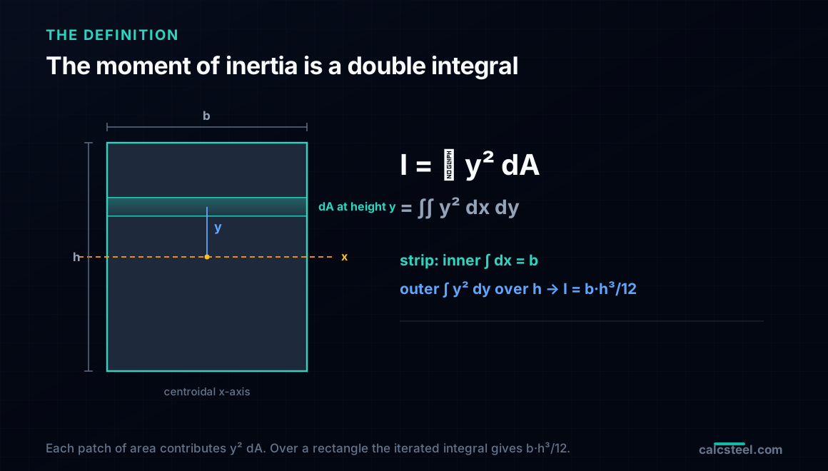
Here is the whole definition in one line, and the rest of the guide is this line made concrete: the moment of inertia of a cross-section about its centroidal axis is the double integral of y² over the area, where y is the distance from the axis to each little patch of area dA. Written out, I = the double integral over the area of y² dA. Add up y² for every speck of material in the face of the beam, weighted by how much area sits there, and you have I. No table to trust, no formula to recall, just the integral you already know how to do.
We will do it on a real member: a welded plate girder, the deep built-up beam you design when no rolled section is big enough, made of two flange plates and a web plate. Because you build it, there is no catalogue value to look up; you have to integrate. By the end you will have set up the double integral, watched it produce the familiar bh³/12 for a single plate, seen the parallel-axis theorem fall out of it for free, and evaluated it over the whole girder to Ix = 7.356 × 10⁹ mm⁴. Every number was checked against a brute numerical sum of y² dx dy and against the Green's-theorem integral the moment of inertia calculator runs in production, and all three agree to the last digit.
The double integral, in one refresher
Strip it back to the calculus first. A double integral of a function f over a two-dimensional region R, written as the double integral over R of f(x, y) dA, adds up the value of f over every infinitesimal patch of area dA inside R. When f is 1, the double integral is just the area of R. When f is something that varies across the region, the integral is the accumulated total of that something, area-weighted.
The trick that makes a double integral computable is that the area element factors: dA = dx dy. That turns the single double integral into a nested pair of ordinary integrals, an iterated integral. You integrate over x first, holding y fixed, which sweeps a horizontal strip; then you integrate that result over y, which stacks the strips from the bottom of the region to the top. Fubini's theorem says the order does not matter for the well-behaved regions a steel section is made of, so you can also go y first, then x. Either way, a double integral is two ordinary integrals done one after the other.
That is the entire machine. For section properties the function f is never complicated: it is 1 for area, it is y for the first moment that locates the centroid, and it is y² for the moment of inertia. The region R is the cross-section. All the work is in the region, not the integrand, which is exactly why a built-up girder made of rectangles is the perfect place to see it: over a rectangle the limits are constants, and the iterated integral is two clean steps.
Why the moment of inertia is a double integral, and not a formula
Where does y² come from? Bend a beam and its cross-section rotates about the neutral axis. A fibre a distance y from that axis stretches in proportion to y, so it carries a stress proportional to y, and the force it contributes is that stress times its area, proportional to y·dA. But we do not want the force, we want the moment of that force about the axis, which is the force times its lever arm y again. One y from the strain, one y from the lever arm, and the contribution of each patch to the bending resistance is y² dA. Sum it over the whole face and you have the section's resistance to bending, the moment of inertia.
This is why I appears in the two equations every structures course leans on. The bending stress is σ = M·y / I, and the curvature is M / (E·I). In both, I is the section's share of the job, and it is large exactly when a lot of area sits at large y, because those patches contribute y² and y² grows fast. That single fact, that the integrand is y² and not y, is the whole reason an I-beam puts its material in flanges far from the axis, and it is the reason a plate girder is deep. The shape of the section beats its weight because the integral rewards distance quadratically.
So the moment of inertia is not a definition you accept and a formula you look up. It is a double integral with a specific, physical integrand, and for any region whose boundary you can describe, you can evaluate it. The rest of this guide does exactly that, starting with the single rectangle every plate girder is built from.
One rectangle from scratch: where bh³/12 actually comes from
Take a single plate, a rectangle of width b and height h, and put the x-axis through its own centroid so y runs from −h/2 at the bottom to +h/2 at the top, and x from −b/2 to +b/2. Write the moment of inertia as an iterated integral with those constant limits:
Ix = ∫ from −h/2 to +h/2 [ ∫ from −b/2 to +b/2 of y² dx ] dy.
Do the inner integral first, over x. The integrand y² does not contain x at all, so integrating it over x from −b/2 to +b/2 just multiplies it by the width: the inner integral is y²·b. Geometrically you swept a horizontal strip of height dy across the full width b, and every point in the strip is at the same distance y, so the strip contributes y²·(b dy). The two-dimensional integral has become a one-dimensional one.
Now the outer integral, over y. Pull the constant b out front and integrate y²:
Ix = b · ∫ from −h/2 to +h/2 of y² dy = b · [ y³/3 ] from −h/2 to +h/2 = b · ( h³/24 + h³/24 ) = b·h³/12.
There it is. The bh³/12 you have written a hundred times is not a formula handed down from a table, it is the number the double integral produces for a rectangle about its own centroid. The cube on h is the y³ from integrating y², and it is why depth is so powerful: double the height of a plate and its own inertia goes up eightfold. Every plate in the girder, flange or web, uses this same result. What changes from plate to plate is only where its centroid sits relative to the girder's axis, and that is the next step.
The parallel-axis theorem falls out of the same integral
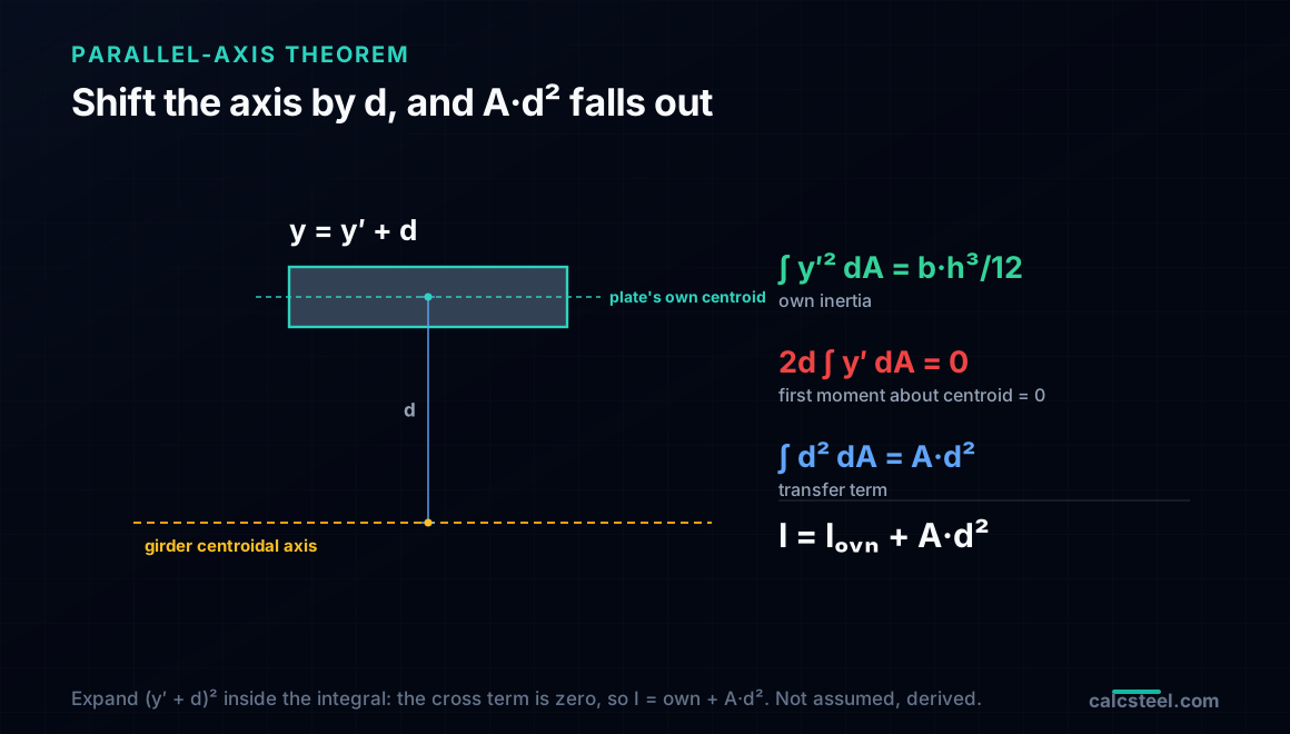
A flange plate does not sit on the girder's centroidal axis, it sits far above or below it. So we need its inertia about the girder's axis, not its own. Call the distance between the two axes d, and let y′ be the coordinate measured from the plate's own centroid, so the girder-axis coordinate is y = y′ + d. Substitute that into the integral and expand the square:
I = the double integral of (y′ + d)² dA = the double integral of ( y′² + 2·d·y′ + d² ) dA.
Split it into three integrals and read each one. The first, the double integral of y′² dA, is the plate's inertia about its own centroid, the b·h³/12 we just derived. The third, the double integral of d² dA, has a constant integrand, so it is simply d² times the area, A·d². The middle term is the interesting one: 2·d times the double integral of y′ dA. That integral is the first moment of area about the plate's own centroid, and the first moment about a centroid is zero by the very definition of a centroid. The cross term vanishes.
What is left is the parallel-axis theorem:
I = I_own + A·d² = b·h³/12 + A·d².
Notice that we did not invoke it as a separate rule to be memorised. It fell out of the double integral the moment we shifted the axis, and the only reason it is clean is that the centroidal first moment is zero. This is the whole toolkit for a built-up section: each plate contributes its own bh³/12 plus its area times the square of its distance to the shared axis. Sum those over the plates and you have the girder. Time to do it.
The plate girder, evaluated from scratch
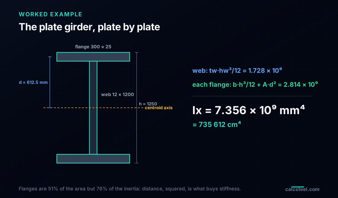
Here is the girder. Two flange plates, each b = 300 mm wide by tf = 25 mm thick, and a web plate tw = 12 mm thick by hw = 1200 mm deep, welded into a doubly-symmetric I with a total depth h = 1250 mm. Because it is symmetric top to bottom, the centroid sits at mid-depth, 625 mm from either extreme fibre, and the shared axis is obvious without any calculation. (When it is not obvious, the first-moment integral finds it; see the next section.)
Apply the toolkit plate by plate. First the web, which straddles the axis so its distance d is zero and only its own inertia counts:
I_web = tw·hw³/12 = 12 × 1200³ / 12 = 1,728,000,000 mm⁴.
The web is 1200 mm deep, and that depth cubed is why a thin 12 mm plate still contributes 1.73 × 10⁹ mm⁴ on its own. Now each flange. Its own inertia is tiny, because a 25 mm thick plate has almost no depth of its own:
I_flange,own = b·tf³/12 = 300 × 25³ / 12 = 390,625 mm⁴.
But its centroid sits d = hw/2 + tf/2 = 600 + 12.5 = 612.5 mm from the girder axis, and the A·d² transfer term is enormous:
A·d² = (300 × 25) × 612.5² = 7500 × 375,156.25 = 2,813,671,875 mm⁴.
So each flange delivers 390,625 + 2,813,671,875 = 2,814,062,500 mm⁴, of which the transfer term is 99.99%. The own-inertia of a flange is a rounding error; a flange is nothing but area parked far from the axis. Add the three plates:
Ix = 2 × 2,814,062,500 + 1,728,000,000 = 7,356,125,000 mm⁴ ≈ 7.356 × 10⁹ mm⁴.
That is 735,612 cm⁴, and it came entirely from the double integral: bh³/12 for each plate, A·d² to move it to the shared axis, summed. The two flanges alone supply 5.63 × 10⁹ mm⁴, more than three-quarters of the total, and they do it through distance, not area: they are only 51% of the section's area but they carry 76% of its inertia. That is the double integral rewarding y² at work.
Checked three ways: hand, grid, and the production engine
A number this large is easy to fumble, so it is worth proving three independent ways, which is exactly what the benchmark behind this article does.
1. From scratch, the plate-by-plate double integral above: Ix = 7,356,125,000 mm⁴.
2. A brute numerical double integral. Forget the formulas and go back to the definition: lay a fine grid of cells over the entire face of the girder, compute y² times the cell area for every cell, and add them up. That is the double integral of y² dA done as a literal Riemann sum, with no bh³/12 and no parallel-axis theorem anywhere in sight. The grid returns 7,356,124,700 mm⁴, which matches the hand value to four parts in a hundred million. The formulas really are just the integral, evaluated cleverly.
3. The shipping engine. The CalcSteel moment-of-inertia calculator does not grid the interior; it walks the boundary, using Green's theorem to turn the area integral of y² dA into a single loop of line integrals around the outline, the polygon method described in our numerical integration guide. Fed the girder's 12-vertex outline, that production code returns Ix = 7,356,125,000 mm⁴, identical to the hand value.
Three roads, one number: the by-hand iterated integral, the brute grid, and Green's theorem on the boundary all land on 7.356 × 10⁹ mm⁴. That is what it means for the moment of inertia to be a double integral: every honest way of evaluating that integral has to give the same answer, and they do.
Strong axis, weak axis, and the product of inertia
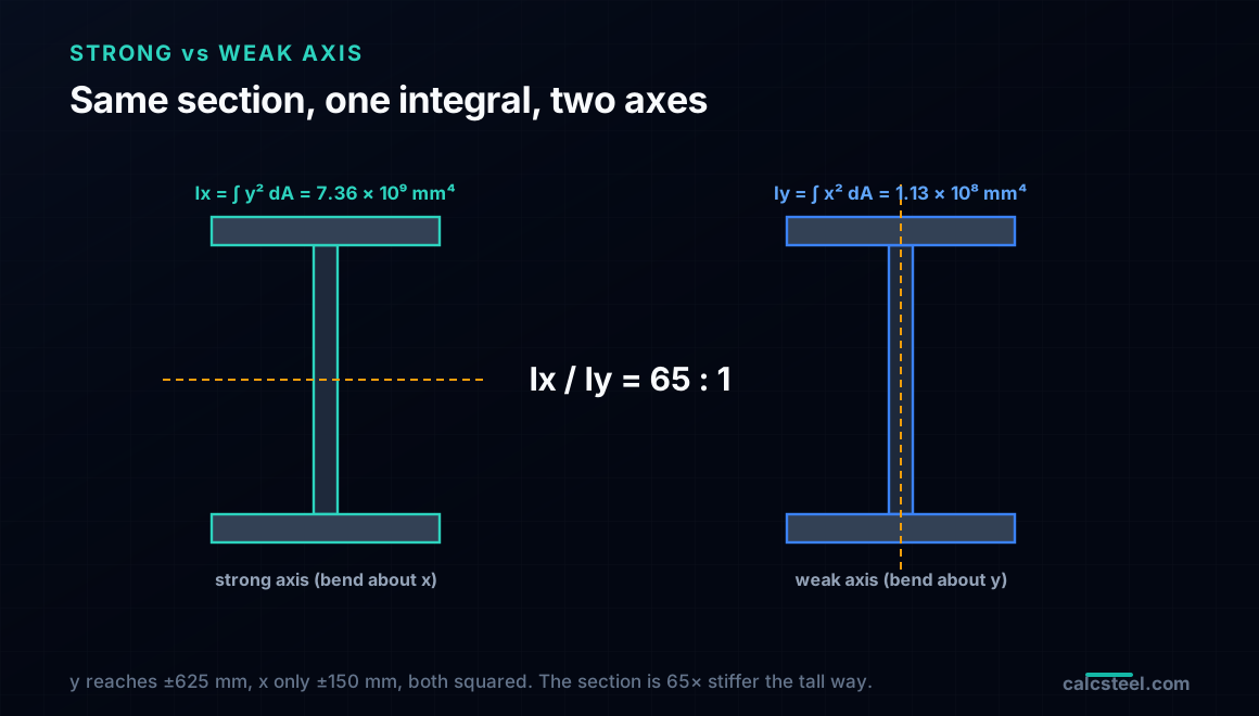
Turn the same integral ninety degrees. The moment of inertia about the vertical centroidal axis, the weak axis, swaps the integrand for x²: Iy = the double integral of x² dA. Now it is the horizontal spread of the material that counts, and the web, being only 12 mm wide, contributes almost nothing. The flanges, 300 mm wide, dominate:
Iy = 2 × (tf·b³/12) + hw·tw³/12 = 2 × (25 × 300³/12) + 1200 × 12³/12 = 112,672,800 mm⁴.
Compare the two: Ix = 7.356 × 10⁹ against Iy = 1.127 × 10⁸ mm⁴, a ratio of 65 to 1. The identical section is 65 times stiffer bending about the strong axis than the weak one, which is the entire reason a plate girder is used the tall way up and needs bracing to stop it buckling sideways about that soft weak axis. The double integral makes the asymmetry precise: y ranges to ±625 mm but x only to ±150 mm, and both enter squared.
There is a third one, the product of inertia Ixy = the double integral of x·y dA, which tells you whether your x and y are the true principal axes. For this girder it is exactly zero, and you can see why straight from the integral: the section is symmetric about the y-axis, so for every patch at +x there is a mirror patch at −x with the same y, and their x·y contributions cancel in pairs. Any axis of symmetry forces Ixy = 0 and makes the drawing axes the principal axes, which is why doubly-symmetric sections never need the Mohr's-circle rotation that an unsymmetric section does.
When the flanges are unequal: the integral finds the centroid too
The symmetric girder let us place the axis by eye. Real girders are often monosymmetric: a wide bottom flange to carry a composite deck, a narrower top flange. Then the centroid is not at mid-depth, and you cannot apply the parallel-axis transfers until you know where it is. The same family of integrals hands it to you. The first moment of area, Q = the double integral of y dA, divided by the total area, is the centroid height: cy = Q / A. It is the y-weighted average position of the material.
Take a girder with a 400 × 32 mm bottom flange, a 12 × 1150 mm web, and a 250 × 20 mm top flange, total depth 1202 mm. Summing y dA plate by plate (each plate's area times its own centroid height) and dividing by the total area A = 31,600 mm² gives:
cy = Q / A = 460.2 mm above the bottom fibre,
not the mid-depth 601 mm: the heavy bottom flange drags the centroid down toward itself, exactly as the y-weighted average should. Only now do the parallel-axis transfers make sense, each plate's d measured from this 460.2 mm axis, and the double integral returns Ix = 7.02 × 10⁹ mm⁴ about it. Because the axis is off-centre, the two fibres are at different distances, 460 mm below and 742 mm above, so the section has two different section moduli, Sx = 15,261 cm³ toward the bottom and 9,467 cm³ toward the top. The shipping engine, fed this outline, reproduces the centroid to 460.171 mm and the inertia to the last digit. The integral that gives you I is the same one that told you where its axis was.
What the number is worth: deflection and stress
The moment of inertia is not a trophy, it is what the two design checks divide by. Put the symmetric girder to work as a 12 m simply-supported span under a service load of w = 40 kN/m. The maximum moment is the familiar wL²/8 = 720 kN·m, and the two things you actually check both run through the Ix = 7.356 × 10⁹ mm⁴ you integrated.
Deflection. The midspan sag of a uniformly loaded simple span is 5·w·L⁴ / (384·E·I). With E = 210,000 MPa for steel, that is 6.99 mm, a slenderness of L/1716, comfortably inside the usual L/360 serviceability limit. Halve the inertia and the beam would sag twice as far: the deflection is inversely proportional to the very integral we evaluated.
Stress. The extreme-fibre bending stress is σ = M·c / I, with c = 625 mm to the outer fibre. That gives 61.2 MPa, a fraction of the yield stress, so the girder is nowhere near its bending capacity at this load. Both numbers, the millimetres it sags and the megapascals it feels, come out of dividing by I, which is why getting the double integral right is not an academic exercise. It is the denominator of the two checks that decide whether the beam is safe and stiff enough. If you would rather watch those numbers move as you resize the plates, the calculator below runs the same integral live.
Try it: integrate a section yourself
Build a section below and read its moment of inertia straight off. Change the depth, change the flange width, and watch Ix respond. Two habits will make the double integral intuitive as you play. First, widen a flange and watch Ix barely move, then move that same flange outward and watch it jump: the integral rewards distance squared, not area. Second, compare Ix and Iy for the same section and feel how far apart they are on anything tall and thin, the 65-to-1 of the girder above.
The calculator is the front end of the same engine CalcSteel uses in a full analysis, so the I it reports is the one a real deflection and stress check would use. For the sibling story, where the very same area integrals are evaluated on an arbitrary outline by walking its boundary, the numerical integration guide picks the thread up. And for the plain-language version aimed at rolled sections rather than built-up plates, start with why beam shape beats weight.
Formula — hover a variable to highlight it on the drawing
Ix = [ b·h³ − (b − tw)·hw³ ] / 12= 1,845.6 cm⁴(hw = h − 2·tf)
Iy = [ 2·tf·b³ + hw·tw³ ] / 12= 141.9 cm⁴
Root fillets are neglected — rolled-section tables run 1–5% higher on Ix.
Parallel-axis theorem, live — Ix = Σ ( I₀ + A·d² )
| Part | A (cm²) | d (cm) | I₀ (cm⁴) | A·d² (cm⁴) | I₀ + A·d² (cm⁴) |
|---|---|---|---|---|---|
| Web | 10.25 | 0 | 286 | 0 | 286 |
| Flange (top) | 8.5 | 9.58 | 0.512 | 779.3 | 779.8 |
| Flange (bottom) | 8.5 | 9.58 | 0.512 | 779.3 | 779.8 |
| Σ = Ix | 287 | 1,558.6 | 1,845.6 |
Exact rectangle parts (web + two flanges) about the section centroid — the flange A·d² transfer terms are the whole story of the I-beam. Change any dimension above and watch the table re-derive.
Section properties
Moment of inertia Ix
1,845.6 cm⁴
1.846 × 10⁷ mm⁴
Moment of inertia Iy
141.9 cm⁴
1.419 × 10⁶ mm⁴
Area A
27.25 cm²
Mass
21.39 kg/m
Section modulus Sx
184.6 cm³
Section modulus Sy
28.39 cm³
Plastic modulus Zx
209.7 cm³
Plastic modulus Zy
43.93 cm³
Radius of gyration rx
8.23 cm
Radius of gyration ry
2.28 cm
Centroid x̄ (from left)
50 mm
Centroid ȳ (from bottom)
100 mm
Local slenderness — NBR 8800 / AISC 360 fingerprint
Flange
λ = b / 2·tf = 5.88
λp = 10.75 · λr = 28.28
Web
λ = hw / tw = 32.68
λp = 106.3 · λr = 161.2
Flexure limits per AISC 360 Table B4.1b (≈ NBR 8800 Annex F), fy = 250 MPa, E = 200 GPa — λp/λr scale with √(E/fy). Compact sections reach the full plastic moment Mp = Z·fy; non-compact and slender elements are capped by local buckling.
Closest standard profiles — matched by Ix against 876 real catalog sections
Ix = 1,845.6 cm⁴ (-0.0%)
Iy = 141.9 cm⁴ (-0.0%)
21.39 kg/mlightest
Best match — design checks
Ix = 1,844.2 cm⁴ (-0.1%)
Iy = 902.5 cm⁴ (+535.8%)
34.19 kg/m#2 by weight
Design checks
Ix = 1,838.7 cm⁴ (-0.4%)
Iy = 1,838.7 cm⁴ (+1195.4%)
43.96 kg/m#3 by weight
Design checks
Same 1,309-profile database that powers the CalcSteel 3D editor and profile pages — ABNT cold-formed (Ue, U, rounds), AISC (W, HSS, L, Pipe), European (IPE, HEA, HEB, HEM, UPN) and Indian (ISMB/ISMC) series. Opening a match carries your custom section along as the comparison baseline.
Five ways the integral gets misread
The mistakes are consistent, and each is a misreading of the double integral rather than of the girder:
1. Using bh³/12 for a plate that is off the axis. The clean bh³/12 is the plate's inertia about its own centroid only. For a flange 612.5 mm away, the A·d² transfer is 7,200 times larger than the bh³/12, and dropping it is the single most common way a hand-built I comes out far too small.
2. Measuring y from the wrong axis. The y in y² dA is the distance to the section's centroid, not to the bottom fibre or the drawing origin. On the monosymmetric girder that means finding cy = 460.2 mm first, from the first-moment integral, and only then measuring every d from there.
3. The units-to-the-fourth trap. I carries units of length to the fourth power. A factor of 10 in your length is a factor of 10,000 in I, and the classic slip is mixing mm⁴ and cm⁴: 7.356 × 10⁹ mm⁴ is 735,612 cm⁴, a division by 10⁴, not 10. Get the power wrong and the deflection is off by orders of magnitude.
4. Confusing Ix with Iy. The strong-axis Ix uses y² and rewards depth; the weak-axis Iy uses x² and rewards width. They differ by 65 times on this girder. Feed the weak-axis value into a strong-axis deflection check and the beam looks 65 times too flexible.
5. Forgetting the cube is on the depth. Because the integral of y² brings an h³, the depth of a plate matters far more than its thickness or width. Doubling a web's thickness doubles its inertia; doubling its depth multiplies it by eight. Any instinct built on area alone, rather than on the y² the integral actually weights, will misjudge which change helps.
What the engine does under the hood
When CalcSteel reports a moment of inertia it is evaluating the same double integral you just did by hand, only it never touches bh³/12 or the parallel-axis theorem. It takes the outline of the section as a list of vertices and applies Green's theorem, which converts the area integral of y² dA into a single loop of line integrals around the boundary: one arithmetic pass over the edges, exact for any polygon, no meshing and no formula table. For the girder in this article we ran that production code on the 12-vertex outline and it returned 7,356,125,000 mm⁴, the same number the plate-by-plate hand integral gave, because they are the same integral read two ways: over the interior, or around the edge.
That is the honest answer to the student who asks what the double integral was for. It is not background for the exam, it is the definition of the number that decides whether a beam is stiff enough, and the software you will use every day is computing exactly that integral. You do not have to trust it as a black box, because you can set the integral up yourself, evaluate it over the rectangles of a built-up section, and check the machine against your own hand. For the neighbouring pieces of the same calculus, the integrals in structural engineering overview maps where each one lands, and Castigliano's theorem shows the derivative side of the same coin at work on a truss.
Sources
- 1.Stewart, J., Calculus: Early Transcendentals (double integrals over general regions, iterated integrals and Fubini's theorem)
- 2.Gere & Goodno, Mechanics of Materials (moments of inertia of areas, the parallel-axis theorem, products of inertia)
- 3.Hibbeler, R.C., Structural Analysis (section properties and built-up members)
- 4.AISC Steel Construction Manual (built-up and welded plate girder cross-sections)
Try CalcSteel for free
Model, analyze and design steel structures in your browser. No install, no signup.
Open the 3D editor