Lateral Bracing for Trusses: the Compression-Chord Criterion Behind the Code
The top chord of a truss is a column, and its buckling strength is set by the distance between its lateral braces, not by the web members. Here is the criterion behind the code, with a worked check on a real 24 m truss where the same SHS 120 chord passes at 87 % braced every 3 m and fails at 221 % braced every 6 m.
Key takeaways
- The compression chord of a truss is a column: it carries C = M/d, and it buckles between the points where something actually holds it in place.
- A chord has two unbraced lengths. In-plane, the web members frame in at every panel point, so Lx = the panel (3.0 m). Out-of-plane, only the lateral bracing counts, and the web members do nothing, so Ly = the spacing of the braces.
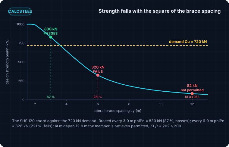
- Buckling strength falls with 1/L², so the length that governs is the larger one. Our SHS 120 x 120 x 8 chord carries Cu = 720 kN: braced laterally every 3.0 m it passes at 87 %, braced every 6.0 m it fails at 221 %, and braced only at midspan (12.0 m) it is not even permitted, KL/r = 262 > 200.
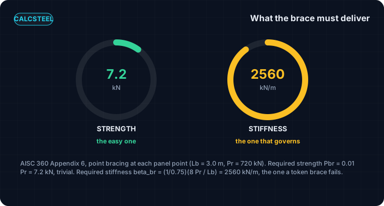
- AISC 360 Appendix 6 says the brace must deliver two things at each panel point: strength Pbr = 0.01 Pr = 7.2 kN, and stiffness beta_br = 2560 kN/m. The stiffness is what a token brace fails.
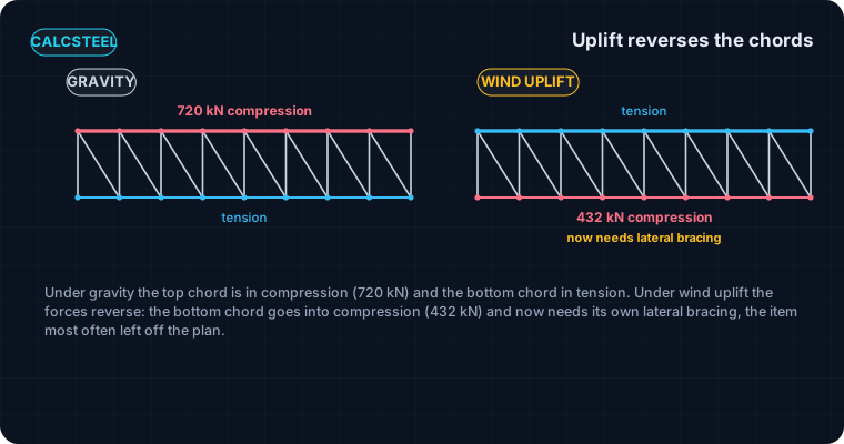
- On wind uplift the load reverses and the bottom chord goes into compression (432 kN here), so the bottom chord now needs its own lateral bracing, the case that gets left off the roof plan.
The top chord of a truss is a column
A truss looks like a web of skinny members, but under gravity load its top chord is doing one blunt job: carrying a large compression, panel after panel, from one support to the other. That makes the top chord a column laid on its side. And like any column, what it can carry is not set by its area or its yield strength. It is set by buckling, and buckling is set by the distance between the points where something actually holds the chord in place.
Here is the part that trips people up, and it is specific to trusses. The web members, the verticals and diagonals, meet the top chord at every panel point. It is tempting to say the chord is therefore braced at every panel point, full stop. That is only half true. The web members hold the chord in the plane of the truss. They do almost nothing to stop the chord from bowing sideways, out of the plane of the truss. Sideways, the chord is only held where you put a lateral brace: a purlin, a strut, a line of bridging tied back to something stiff.
So the whole design turns on one distance, the spacing of the lateral braces on the compression chord, and this article is about the criterion behind it. We derive it from Euler, then run a full worked check on a real 24 m truss whose SHS 120 chord carries 720 kN, and watch the same chord pass or fail depending only on how often it is braced. It is the truss-specific cousin of our general piece on what a brace must actually deliver.
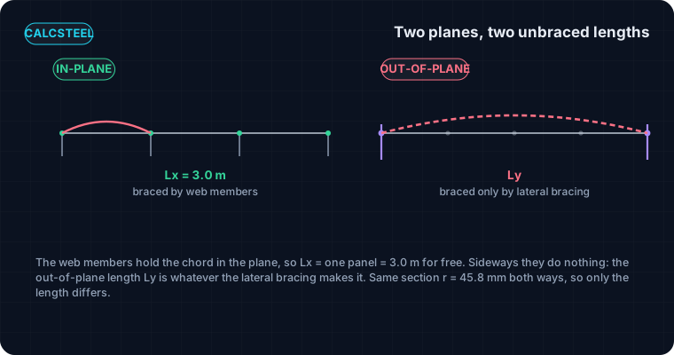
Two planes, two unbraced lengths, and the web members brace only one
Give a compression member a nudge and it buckles about its weakest available axis over its longest unbraced length. A truss chord has two quite different unbraced lengths, and the mistake is to use the short one for both.
- In-plane (about the axis perpendicular to the truss plane). Here the chord wants to bow within the vertical plane of the truss. But every panel point has a vertical and a diagonal framing into it, and those web members hold the panel point in the plane. So the in-plane unbraced length is one panel: Lx = 3.0 m, automatically, for free.
- Out-of-plane (about the axis in the truss plane). Here the chord wants to bow sideways, out of the plane. The web members lie in that plane; they offer no sideways restraint at all. The chord is held sideways only where a real lateral brace ties it off. If you brace it every panel, Ly = 3.0 m; every other panel, Ly = 6.0 m; only at midspan, Ly = 12.0 m.
For a doubly-symmetric section like the square hollow section we will use, the radius of gyration is the same about both axes, so the two checks differ only by their length. The chord does not care that one length came from web members and the other from purlins. It buckles over whichever unbraced length is longer, because, as we are about to see, that is the one that costs the most strength.
The criterion behind the code, from Euler
Start from the buckling load of an ideal strut, the Euler result: Pe = π²EI / (KL)². Divide by the area and write it in the code's form, and the usable stress is a function of one number, the slenderness KL/r:
Fe = π²E / (KL/r)², then Fcr from AISC 360 E3
Two facts about that expression drive the whole design. First, the strength depends on (KL/r)² in the denominator, so it falls with the square of the unbraced length. Halve the length and you nearly quadruple the capacity; double it and you cut the capacity to roughly a quarter. Second, because KL/r appears only through the length and the radius r, and a square chord has one r, the only knob that separates the in-plane and out-of-plane checks is the unbraced length itself.
That gives us the criterion in one sentence. Lateral bracing exists to shorten Ly until the out-of-plane check is no worse than the in-plane check the web members already gave you for free. Brace the chord sideways at every panel point and Ly = Lx = 3.0 m, so the two checks coincide and the chord works at its in-plane strength. Leave gaps and Ly grows, the out-of-plane curve collapses down the Euler line, and the chord fails at a force it easily carries in-plane. The rest of the article is putting numbers to that sentence.
Where the demand comes from: C = M over d
The truss and the load
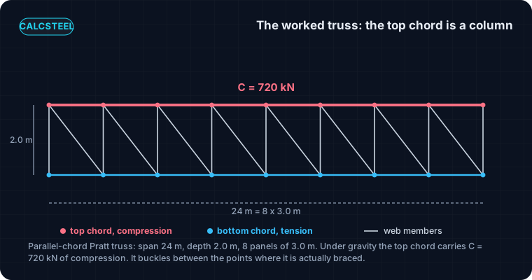
Take a parallel-chord Pratt roof truss spanning S = 24 m, depth d = 2.0 m centre to centre of chords, divided into eight 3.0 m panels. Put a factored gravity load of w = 20 kN/m on the top chord (roof, services and a heavy snow case), delivered as panel-point loads. Each support carries 240 kN.
The chord force by hand, then by the engine
A parallel-chord truss carries global bending as a couple: the chords are the flanges, the depth d is the lever arm. Cut the truss at midspan and take moments. The chord force is the global moment divided by the depth:
C = Mmax / d, Mmax = wS² / 8 = 20 · 24² / 8 = 1440 kN·m
C = 1440 / 2.0 = 720 kN (compression, top chord)
We ran the same truss on the shipping CalcSteel FEM engine, as a pin-jointed model, and read the axial force in every member. The most-loaded top-chord panel, next to midspan, comes back at 720.0 kN compression, matching the method-of-sections value to the last digit. That is the demand the chord, and its bracing, has to survive. It also confirms the intuition: the chord force is largest near midspan, exactly where you least want a lateral brace missing.
Worked check, part 1: the chord braced at every panel
Provide a hot-finished SHS 120 x 120 x 8 in S355 for the top chord: area A = 3584 mm², second moment I = 753 cm⁴, radius of gyration r = 45.8 mm, the same about both axes. First, brace it laterally at every panel point, so Ly = Lx = 3.0 m. The slenderness is
KL/r = 3000 / 45.8 = 65.4
That is below the E3 boundary 4.71√(E/Fy) = 111.8, so we are in the inelastic range and Fcr = 0.658^(Fy/Fe) times Fy. With Fe = π²E / 65.4² = 461 MPa, Fcr = 257 MPa. The design strength is
φPn = 0.90 · 257 · 3584 / 1000 = 829 kN
Against the 720 kN demand that is a utilisation of 87 %. The chord passes, comfortably but not wastefully. Notice what did the work: nothing about the section changed, we simply made sure the out-of-plane length equalled the in-plane length the web members already provided. When the two lengths match, the chord delivers its full column strength.
Worked check, part 2: the same chord, braced too far apart
Now keep the exact same chord and the exact same 720 kN demand, and change one thing: brace it laterally only at every other panel point, so Ly = 6.0 m. The web members still give Lx = 3.0 m in-plane, so the in-plane check is unchanged and still passes. But out-of-plane the length has doubled:
KL/r = 6000 / 45.8 = 130.9 (now past 111.8, so elastic buckling)
Fe = 115 MPa, Fcr = 0.877 Fe = 101 MPa, φPn = 326 kN
The utilisation is 720 / 326 = 221 %. The chord that passed at 87 % now fails by more than a factor of two, and nothing changed but the brace spacing. Doubling Ly quartered the strength, exactly as the 1/L² curve promised.
Push it once more, to a single lateral brace at midspan, Ly = 12.0 m. Then KL/r = 262, which is past the recommended upper limit of 200 in AISC 360 for compression members. That chord is not permitted at all, before you even compute a strength (it would be 82 kN, a utilisation of 884 %). The lesson is the trap in one line: the web members lull you into thinking the chord is braced at 3 m, but out-of-plane it is only braced where you drew a purlin.
What the brace itself has to deliver: strength and stiffness
Shortening Ly assumes the brace is real. A line on a drawing is not a brace; the code asks it to deliver two separate things, and a token member can satisfy one while failing the other. This is AISC 360 Appendix 6, point (nodal) bracing, and it is the same two-part test we cover in depth for columns and beams in bracing stiffness and strength.
For a point brace holding the chord at each panel point, with the braced chord force Pr = 720 kN and brace spacing Lb = 3.0 m:
- Strength. The brace must carry Pbr = 0.01 Pr = 7.2 kN. That is small, only 1 % of the chord force, which is why strength is rarely the problem.
- Stiffness. The brace, and everything back to a stiff point, must be at least beta_br = (1/φ)(8 Pr / Lb) = (1/0.75)(8 · 720 / 3.0) = 2560 kN/m. This is the requirement a flimsy brace fails.
The stiffness number is the one to respect. A brace can be plenty strong for 7.2 kN and still be too flexible: if it stretches or the connection slips under load, the chord's effective brace point moves, Ly is not really 3.0 m, and the buckling you thought you prevented happens anyway. A brace has to be present, strong enough, and stiff enough, and the last one is the one that quietly fails.
See it yourself: watch the strength fall with the length
The whole worked check is one curve, the collapse of the compression strength as the unbraced length grows. You can drive it below. Take a compression member, set its section, and push its length up: the critical load slides down the Euler curve and the usable strength with it. That is exactly the axis a lateral brace lets you stay near the top of.
Set the length to your panel size and read the strength; then to twice the panel size and watch it fall to roughly a quarter. That factor is why bracing spacing, not section size, is usually the cheapest way to make a truss chord work. When you are done, the effective length K factor piece explains the KL in the formula, and Euler buckling sets up why the curve is a square law.
End conditions (buckling case)
Pinned – Pinned
Cross-section
Slenderness KL/r
134.7
limit 200 · OK
Euler Pcr (elastic)
310.7 kN
Fe = 108.9 MPa
AISC 360 φcPn
245.2 kN
Fcr = 95.5 MPa · elastic
NBR 8800 Nc,Rd
247.7 kN
χ = 0.382 · λ₀ = 1.52
Code vs code — same column
Nc,Rd / φcPn = 1.010
Both codes share the 0.658 / 0.877 buckling curve — the ~1% gap is purely φc = 0.90 (AISC) vs 1/γa1 = 0.909 (NBR).
Demand check — Nd = 150 kN
Step-by-step derivation — live for YOUR column
IPE 200 · L = 3 m · K = 1 · fy = 250 MPa
- 1
Slenderness ratio
λ = K·L/r = 1 × 3000 / 22.28 mm
λ = 134.7 (≤ 200 ✓)
- 2
Euler elastic buckling stress and load
Fe = π²E/λ² = π² × 200,000 / 134.7² · Pcr = Fe·A = Fe × 2854 mm²
Fe = 108.9 MPa · Pcr = 310.7 kN
- 3
Buckling regime (AISC E3)
4.71·√(E/fy) = 4.71·√(200,000/250) = 133.2 < λ = 134.7
elastic buckling → use E3-3 (0.877·Fe)
Elastic range: capacity no longer depends on fy — only geometry (r, K, L) helps.
- 4
AISC 360 critical stress and design capacity
Fcr = 0.877 · Fe = 0.877 × 108.9 = 95.5 MPa · φcPn = 0.9 × Fcr × A
Pn = 272.5 kN · φcPn = 245.2 kN
- 5
NBR 8800 reduction factor and design capacity
λ₀ = √(fy/Fe) = 1.515 > 1.5 → χ = 0.877/λ₀² = 0.382 · Nc,Rd = χ·A·fy/1.1
Nc,Rk = 272.5 kN · Nc,Rd = 247.7 kN
Same 0.658/0.877 curve as AISC — the ~1% difference is φc = 0.90 vs 1/γa1 = 0.909.
Sections that work — 3 lightest of 612 catalog profiles carrying Nd = 150 kN at L = 3 m, K = 1
| Section | kg/m | φcPn (kN) | Nc,Rd (kN) | Util. | |
|---|---|---|---|---|---|
| lightestSHS 80x4 | 9.2 | 164 | 166 | 91% | |
| HSS 76x76x4.8 | 9.9 | 165 | 167 | 91% | |
| CHS 88.9x5 | 10.3 | 172 | 174 | 87% |
Pass criterion: φcPn ≥ Nd (AISC 360 LRFD) AND Nc,Rd ≥ Nd (NBR 8800) AND KL/r ≤ 200, using each section's tabulated-mass area and minimum radius of gyration.
Buckling curve — IPE 200, fy = 250 MPa
Capacity of IPE 200 by unbraced length — K = 1, fy = 250 MPa
| L (m) | KL/r | Pcr Euler (kN) | φcPn AISC (kN) | Nc,Rd NBR (kN) | Regime |
|---|---|---|---|---|---|
| 1 | 45 | 2,796 | 577 | 583 | inelastic |
| 2 | 90 | 699 | 419 | 423 | inelastic |
| 3◀ yours | 135 | 311 | 245 | 248 | elastic |
| 4 | 180 | 175 | 138 | 139 | elastic |
| 5 | 224 ⚠ | 112 | 88 | 89 | elastic |
| 6 | 269 ⚠ | 78 | 61 | 62 | elastic |
| 7 | 314 ⚠ | 57 | 45 | 45 | elastic |
| 8 | 359 ⚠ | 44 | 34 | 35 | elastic |
| 9 | 404 ⚠ | 35 | 27 | 28 | elastic |
| 10 | 449 ⚠ | 28 | 22 | 22 | elastic |
Do not forget the bottom chord: uplift reverses everything
Everything so far braced the top chord because gravity puts it in compression. But a roof truss also sees wind uplift, and uplift reverses the axial forces in both chords. Under a net uplift the top chord goes into tension and the bottom chord goes into compression, and now the bottom chord is the column that needs bracing.
Run the same truss with a factored net uplift of wup = 12 kN/m and the engine returns a bottom-chord compression of 432 kN (Mup/d = 12 · 24² / 8 / 2.0 = 432 kN, matching to the digit). The bottom chord is usually braced far less often than the top, because under gravity it is a tension member and tension members do not buckle. That habit is exactly the trap: the moment uplift can put the bottom chord in compression, its lateral brace spacing has to satisfy the same square-law check as the top chord, or the chord buckles sideways with no roof deck nearby to catch it.
This is the single most-missed item on a truss bracing plan. The top chord gets purlins whether you think about bracing or not; the bottom chord gets a lateral brace only if someone deliberately draws the bottom-chord bracing line for the uplift case. On a light long-span roof, uplift often governs the bottom chord entirely.
Where the brace force goes: the bracing system needs an anchor
A lateral brace at a panel point holds the chord only if the brace itself is held. The 7.2 kN and, more importantly, the 2560 kN/m have to travel from the chord back to something that does not move. Left as a stub sticking out sideways, a brace braces nothing.
In a real roof that anchor is the bracing system: the purlins tie each truss chord to the next, and a line of diagonal bracing in the plane of the roof (or a braced bay of trusses) collects all those little brace forces and carries them to a stiff point, a gable frame, a shear wall, a braced tower. It is the same logic as any steel bracing system: individual braces are only as good as the load path that anchors them. The stiffness check in Appendix 6 is a check on that whole path, brace plus connection plus the system behind it, not just the little strut at the chord.
Two practical consequences. First, the brace force accumulates: the diagonal that gathers ten panel-point braces sees roughly ten times 7.2 kN, not 7.2 kN. Second, stiffness is series: a stiff strut bolted to a floppy system is still a floppy brace. Size the anchor, not just the stub.
Common mistakes and FAQ
The errors that turn a textbook-correct chord into a failed one:
- Using the panel length for the out-of-plane check. The web members brace the chord in-plane only. Out-of-plane, Ly is the lateral brace spacing, which is usually larger. This is the single most common truss bracing error, and it is exactly the 87 % versus 221 % of our worked check.
- Bracing only for strength. The 7.2 kN is trivial; the 2560 kN/m is not. A brace that is strong but soft lets the chord buckle anyway. Check the stiffness of the whole path.
- Forgetting uplift on the bottom chord. Under gravity the bottom chord is in tension and needs no bracing; under uplift it carries 432 kN of compression and does. Leaving it off is the classic long-span roof failure.
- Bracing a chord to nothing. A brace needs an anchor. If the bracing system does not carry the force back to a stiff point, the brace point is not really a brace point.
- Exceeding KL/r = 200. A single midspan brace on our chord gives KL/r = 262, past the code limit, so the member is not permitted regardless of the computed strength.
FAQ
Do the web members brace the top chord? In-plane, yes: the vertical and diagonal at each panel point hold the chord in the plane of the truss, so Lx equals one panel. Out-of-plane, no: they lie in the plane and give no sideways restraint. Out-of-plane you need a separate lateral brace.
How far apart can the lateral braces be? As far as the square-law check allows. For our SHS 120 chord at 720 kN, roughly 3.0 m works (87 %) and 6.0 m does not (221 %). The answer scales with the section's r and the chord force, so it is a calculation, not a rule of thumb, though many designers target Ly close to the panel length so the two checks coincide.
Does the bottom chord ever need lateral bracing? Yes, whenever a load case (wind uplift, or a moving load) can put it into compression. A tension chord does not buckle, but the same chord under reversed load does, and it must satisfy the same check.
Key takeaways
Lateral bracing for a truss is one idea applied carefully: the compression chord is a column, and the braces decide how long a column it is.
- The chord force is C = M/d. Our 24 m truss puts 720 kN into the SHS 120 top chord, engine and hand check agreeing to the digit.
- The chord has two unbraced lengths. The web members give Lx = 3.0 m in-plane for free; the lateral bracing sets Ly out-of-plane, and only Ly is yours to lose.
- Strength falls with 1/L², so the same chord passes at 87 % braced every 3.0 m, fails at 221 % braced every 6.0 m, and is not permitted braced only at midspan.
- Appendix 6 wants the brace to deliver strength (7.2 kN) and stiffness (2560 kN/m), and to carry both back to a stiff anchor. Stiffness governs.
- Uplift reverses the chords: the bottom chord carries 432 kN of compression and needs its own bracing, the item most often left off the plan.
Want to try it on your own truss? The column buckling calculator and the full CalcSteel editor are free to use, and CalcSteel is free for students. Set the chord force, size the section, and let the brace spacing do the work.
Sources
- 1.AISC 360-16, Specification for Structural Steel Buildings (Chapter E, compression; Appendix 6, stability bracing)
- 2.AISC Design Guide 25 and Yura, Fundamentals of Beam Bracing (stiffness and strength of stability bracing)
- 3.Steel Joist Institute, Technical Digest on bracing of open-web steel joists and joist girders
- 4.ABNT NBR 8800, Projeto de estruturas de aco e de estruturas mistas de aco e concreto
Try CalcSteel for free
Model, analyze and design steel structures in your browser. No install, no signup.
Open the 3D editor