Insulated Concrete Form Bracing: the Lateral-Load Criterion Behind the Code
The bracing on an insulated concrete form wall is not what most people think it is. It is not holding back the fresh concrete: that pressure is internal to the form and balanced face to face, so the plastic web ties inside the block carry it. The bracing is there for the external loads while the wall is green, the wind and the plumbing forces, and the code writes those down as a single criterion: a design lateral load that is the greater of the construction wind and a flat minimum applied at the top of the wall. This guide derives that criterion, then runs the real CalcSteel engine on a 3.0 m wall to size the strongback and the diagonal kicker, and finds the code minimum, not the wind, is what governs.
Key takeaways
- The bracing does not resist the fresh-concrete pressure. That pressure pushes both faces of the form equally, so it is balanced and the web ties inside the block carry it. The external bracing resists wind while the concrete is green, plus the alignment and plumbing forces.
- The criterion behind the code is a floor: the design lateral load is the greater of the construction wind (ASCE 7 reduced for a short exposure per ASCE 37) and the ACI 347 minimum of 100 lb/ft (1.46 kN/m) applied at the top of the wall.
- On the CalcSteel engine, that 1.46 kN/m minimum applied at the top (2.63 kN per 1.8 m bay) puts 3.28 kN into the kicker, against only 2.03 kN from a 0.60 kPa construction wind. For this short wall the code minimum governs, which is exactly why it exists.
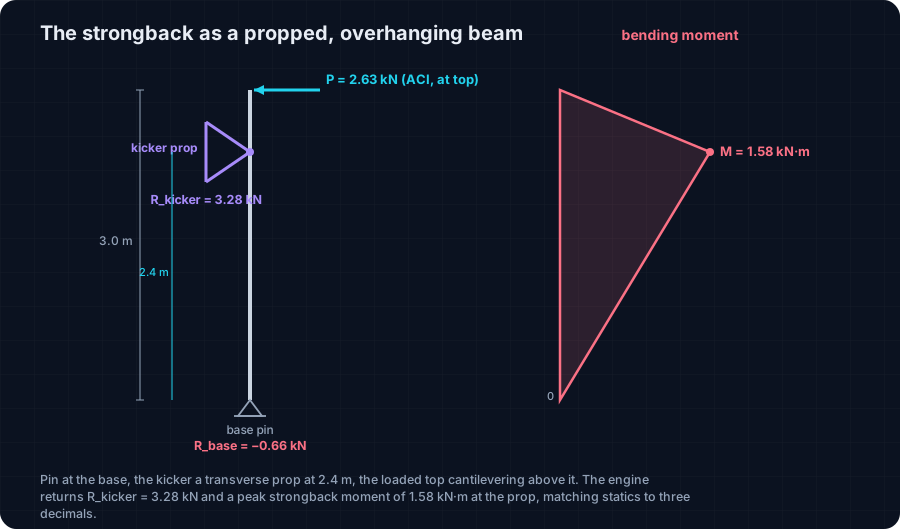
- The strongback is a propped, overhanging beam: pinned at the base, propped by the kicker at 2.4 m, the loaded top cantilevering above it. The engine returns a peak moment of 1.58 kN·m at the kicker and a base reaction of −0.66 kN, a reversal the base anchor has to hold.
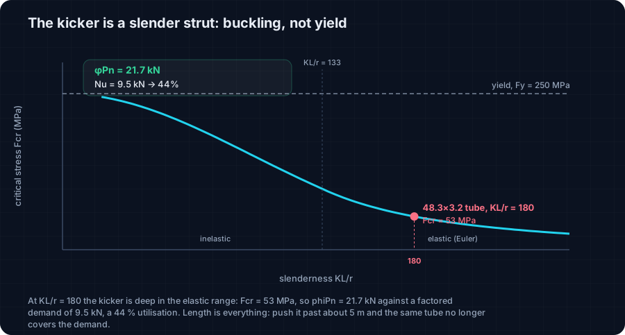
- The kicker is a slender steel strut, so buckling governs, not yield. A 2.88 m, 48.3 × 3.2 tube at KL/r = 180 carries φPn = 21.7 kN against a factored demand of 9.47 kN, a 44% check. Push the kicker past about 5 m and the same tube no longer covers the load.
The brace that does not resist the concrete
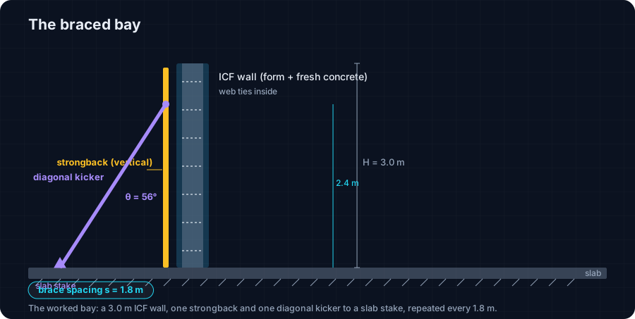
Walk onto an insulated concrete form (ICF) pour the day before the concrete goes in and the wall is a paradox: a full-height wall, plumb and lined, that you could push over with one hand. It is a stack of foam blocks held together by plastic or steel web ties, waiting to be filled. What keeps it straight, plumb and standing until the concrete cures is the bracing: a line of vertical strongbacks down the wall, each held by a diagonal kicker, a turnbuckle prop, staked to the slab.
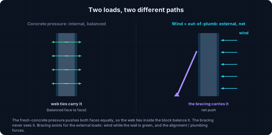
Here is the part that trips up almost everyone the first time they size it. The bracing does not resist the pressure of the fresh concrete. When you fill the form, the liquid concrete pushes out on both faces of the block equally. That push is balanced, internal to the form, and it is carried by the web ties inside each block, not by anything outside. The bracing resists a different, much smaller set of loads: the wind on a wall that has no strength yet, and the alignment and plumbing forces you apply to line it up and hold it there.
This article derives the design criterion for that bracing, the one behind ACI 347 and ASCE 37, then puts numbers on it with the real CalcSteel engine: a 3.0 m wall, kickers every 1.8 m, and a worked check of both the strongback and the diagonal kicker. The surprise at the end is that the code minimum, not the wind, is what sizes the brace. This is the temporary-works cousin of our permanent steel bracing guide: same word, a completely different load.
ICF bracing vs form ties vs shoring: three different jobs
A 45-word definition you can quote: insulated concrete form bracing is the temporary system of vertical strongbacks and diagonal kickers that holds an ICF wall straight, plumb and stable from the moment it is stacked until the concrete has cured, resisting wind and alignment loads while the wall has no strength of its own.
Three things act on a green ICF wall, and each has its own load path. Keeping them separate is the whole game:
- Concrete pressure (the big number, tens of kPa) is internal and balanced. It is resisted by the form ties, the plastic or steel webs moulded into every block. The bracing never sees it.
- Lateral loads (wind, plumbing, incidental placement forces) are external and unbalanced. They are resisted by the bracing, the strongbacks and kickers, the subject of this article.
- Gravity from the work platform (workers, a screed, a hose) is carried by the scaffold brackets that hang off the bracing, a separate check with its own live load.
Confuse the first two and you either massively over-size the kicker (designing it for concrete pressure it will never feel) or, worse, trust the ties to plumb the wall, which is not their job. The bracing and the ties are a division of labour: ties hold the concrete in, bracing holds the wall true.
The load the bracing does not carry
Start with the load everyone reaches for first and then set it aside. Fresh concrete behaves like a heavy fluid, so it pushes horizontally on the form with a pressure that grows with depth and pour rate. In an ICF wall that pressure can reach tens of kilopascals near the base, far larger than any wind. If the bracing had to carry it, the kickers would be enormous.
They are not, because of one word: balanced. The concrete pushes out on the inside face and the outside face with the same pressure at the same depth. Those two pushes are equal and opposite, and what ties them together, literally, is the grid of web ties moulded into the block. The ties go into tension and hold the two faces apart at the design cavity width. The net horizontal force the concrete delivers to the outside world, and therefore to the bracing, is zero.
So the bracing is left with the external loads only: the wind on a wall that cannot yet resist anything, and the alignment and plumbing forces, the deliberate push you apply through the turnbuckle to bring the wall to plumb and the incidental shove of placing and vibrating concrete slightly off centre. Those are the loads the next section turns into a number.
The criterion behind the code, from first principles
Two independent things can push a green wall sideways, and the code refuses to let you pick just one. The first is environmental: wind. The second is operational: the wall is never perfectly plumb, the concrete is never placed perfectly evenly, and the crew is actively pushing on the turnbuckles. Wind you can compute; the operational push you largely cannot. So the code does the sensible thing and sets a floor that covers the part you cannot compute, then tells you to use the larger of the two:
design lateral load = max ( wind , code minimum )
The wind side comes from ASCE 7, but reduced: a form stands for days, not fifty years, so ASCE 37 lets you use a shorter recurrence interval and a lower design wind speed for the construction period. That is a real, defensible reduction, and it is why construction wind pressures are a fraction of the permanent-design value.
The code minimum is the number to remember. ACI 347, the Guide to Formwork for Concrete, requires wall-form bracing to be designed for a horizontal load of at least 100 lb per linear foot of wall (1.46 kN/m), applied at the top. Two details make it bite. First, it is a line load along the whole wall, so a wider brace spacing pulls in more of it. Second, it is applied at the top, the worst possible height for overturning, which maximises the force in the brace. That is deliberate: the minimum is a stand-in for the plumbing and placement loads, and putting it at the top is the conservative assumption. Miss the at the top and you under-design the brace.
Putting numbers on the two load cases
Take the worked wall: height H = 3.0 m, with a strongback and kicker every s = 1.8 m along the length. Each brace looks after a 1.8 m wide strip of wall, its tributary width. Now size the two loads on that strip.
Case A: the ACI 347 minimum
The code minimum is a line load of 1.46 kN/m along the top. Per brace it becomes a single force at the top of the wall:
P = 1.46 × 1.8 = 2.63 kN, applied at H = 3.0 m
Case B: construction wind
Take a construction wind pressure of 0.60 kPa on the wall face, a reasonable ASCE 37 value for a short exposure. Over the 1.8 m strip it is a distributed load down the height:
w = 0.60 × 1.8 = 1.08 kN/m, total 3.24 kN at mid-height
Two loads, two shapes: a point at the very top (Case A) and a triangle-free uniform pressure with its resultant at mid-height (Case B). The point-at-the-top has a longer lever arm about the base, so even though its total (2.63 kN) is smaller than the wind total (3.24 kN), it can still win at the brace. The only way to know which governs is to run both through the strongback, which is the next step.
Worked check, part 1: the strongback
The strongback is the vertical member the loads land on. It is supported in two places: pinned at the base, where its foot is staked to the slab, and propped by the kicker at height 2.4 m. Above the kicker, the top 0.6 m of the strongback cantilevers. In other words it is a classic propped, overhanging beam, turned on its end, and it is statically determinate: the two reactions follow from equilibrium alone.
The governing case
Run both load cases through it on the CalcSteel engine and read off the kicker reaction, the number that sizes the brace:
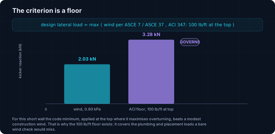
- Case A (ACI minimum, 2.63 kN at the top): the point sits on the cantilever tip, 0.6 m above the prop, so it drives a large prop reaction. Engine: Rkicker = 3.28 kN.
- Case B (wind, 1.08 kN/m): the resultant sits at mid-height, below the prop, with a shorter effective lever. Engine: Rkicker = 2.03 kN.
Case A wins, 3.28 kN against 2.03 kN. The code minimum governs, and it is not close. Take Rkicker = 3.28 kN forward.
Reactions and moment, hand-checked
For the governing case, statics gives the reactions directly. Moments about the base (the prop at 2.4 m carries the tip load at 3.0 m):
Rkicker = P · H / a = 2.63 × 3.0 / 2.4 = 3.28 kN
Rbase = P − Rkicker = 2.63 − 3.28 = −0.66 kN
The base reaction comes out negative: with the load out on the cantilever tip, the base is pulled the other way. That reversal is real and the base anchor has to hold it, a point we return to below. The peak bending moment in the strongback is at the prop, from the cantilevered load:
M = P · (H − a) = 2.63 × 0.6 = 1.58 kN·m
The engine returns Rkicker = 3.28 kN, Rbase = −0.66 kN and M = 1.58 kN·m, matching the hand statics to three decimals. A modest 1.58 kN·m is easy for any proprietary aluminium or steel strongback; the strongback is rarely the problem. The kicker is.
Worked check, part 2: the diagonal kicker
The kicker carries the prop reaction down to the slab stake, and because it runs at an angle it works in pure axial force. It attaches at 2.4 m and the stake sits 1.6 m out from the wall, so it runs at θ = 56° from horizontal over a length of 2.88 m. The horizontal prop reaction is the horizontal component of the kicker force, so:
N = Rkicker / cos θ = 3.28 / cos 56° = 5.92 kN
When the wind or the plumbing push drives the wall toward the braces, that force is compression, and the kicker becomes a slender strut. This is where temporary bracing actually fails, and it is a buckling problem, not a strength one.
Size it as a compression member
Take the standard temporary-works prop, a 48.3 × 3.2 mm steel tube (A = 453 mm², I = 11.6 cm², r = 16.0 mm). With pinned ends (K = 1) over 2.88 m its slenderness is:
KL/r = 1 × 2.88·10³ / 16.0 = 180
That is a very slender member, near the KL/r ≤ 200 practical limit and well past the AISC elastic threshold of 133, so the strut is deep in the elastic (Euler) range. The elastic critical stress and the AISC nominal are:
Fe = π²E / (KL/r)² = 61 MPa, Fcr = 0.877 Fe = 53 MPa
φPn = 0.90 · Fcr · A = 21.7 kN
Against a factored demand of Nu = 1.6 × 5.92 = 9.47 kN (the 1.6 is the ASCE 37 / LRFD factor on the construction lateral load), the utilisation is 9.47 / 21.7 = 44%. The tube passes, comfortably, at this length.
But read the sensitivity, because it is the whole lesson. The strut is elastic, so its capacity falls with the square of the length. Push the same tube past about 5 m, the kind of reach you need on a tall wall or a shallow kicker angle, and φPn drops below the demand. For the kicker, length is everything; the yield strength of the steel barely matters. That is why brace manufacturers publish a maximum kicker length, and why the honest way to feel it is to move the length yourself.
See it yourself: watch the kicker capacity fall with length
The kicker check lives or dies on one curve: how fast the buckling capacity of a slender strut collapses as it gets longer. Rather than take the 21.7 kN on trust, put your own tube in the calculator below and drag the length up. Start near 2.88 m and watch the critical load; keep going toward 5 m and it falls away underneath the 9.47 kN demand. That falling curve is the reason a kicker fails long before it yields.
Change the section too. A bigger diameter lifts the whole curve (capacity scales with the second moment of area), a thinner wall drops it. It is the same physics as a building column, only the member is a scaffold tube and the load is temporary. When you are done, the K factor that sets the end conditions is worth a look in our effective length guide, since a kicker is rarely perfectly pinned.
End conditions (buckling case)
Pinned – Pinned
Cross-section
Slenderness KL/r
134.7
limit 200 · OK
Euler Pcr (elastic)
310.7 kN
Fe = 108.9 MPa
AISC 360 φcPn
245.2 kN
Fcr = 95.5 MPa · elastic
NBR 8800 Nc,Rd
247.7 kN
χ = 0.382 · λ₀ = 1.52
Code vs code — same column
Nc,Rd / φcPn = 1.010
Both codes share the 0.658 / 0.877 buckling curve — the ~1% gap is purely φc = 0.90 (AISC) vs 1/γa1 = 0.909 (NBR).
Demand check — Nd = 150 kN
Step-by-step derivation — live for YOUR column
IPE 200 · L = 3 m · K = 1 · fy = 250 MPa
- 1
Slenderness ratio
λ = K·L/r = 1 × 3000 / 22.28 mm
λ = 134.7 (≤ 200 ✓)
- 2
Euler elastic buckling stress and load
Fe = π²E/λ² = π² × 200,000 / 134.7² · Pcr = Fe·A = Fe × 2854 mm²
Fe = 108.9 MPa · Pcr = 310.7 kN
- 3
Buckling regime (AISC E3)
4.71·√(E/fy) = 4.71·√(200,000/250) = 133.2 < λ = 134.7
elastic buckling → use E3-3 (0.877·Fe)
Elastic range: capacity no longer depends on fy — only geometry (r, K, L) helps.
- 4
AISC 360 critical stress and design capacity
Fcr = 0.877 · Fe = 0.877 × 108.9 = 95.5 MPa · φcPn = 0.9 × Fcr × A
Pn = 272.5 kN · φcPn = 245.2 kN
- 5
NBR 8800 reduction factor and design capacity
λ₀ = √(fy/Fe) = 1.515 > 1.5 → χ = 0.877/λ₀² = 0.382 · Nc,Rd = χ·A·fy/1.1
Nc,Rk = 272.5 kN · Nc,Rd = 247.7 kN
Same 0.658/0.877 curve as AISC — the ~1% difference is φc = 0.90 vs 1/γa1 = 0.909.
Sections that work — 3 lightest of 612 catalog profiles carrying Nd = 150 kN at L = 3 m, K = 1
| Section | kg/m | φcPn (kN) | Nc,Rd (kN) | Util. | |
|---|---|---|---|---|---|
| lightestSHS 80x4 | 9.2 | 164 | 166 | 91% | |
| HSS 76x76x4.8 | 9.9 | 165 | 167 | 91% | |
| CHS 88.9x5 | 10.3 | 172 | 174 | 87% |
Pass criterion: φcPn ≥ Nd (AISC 360 LRFD) AND Nc,Rd ≥ Nd (NBR 8800) AND KL/r ≤ 200, using each section's tabulated-mass area and minimum radius of gyration.
Buckling curve — IPE 200, fy = 250 MPa
Capacity of IPE 200 by unbraced length — K = 1, fy = 250 MPa
| L (m) | KL/r | Pcr Euler (kN) | φcPn AISC (kN) | Nc,Rd NBR (kN) | Regime |
|---|---|---|---|---|---|
| 1 | 45 | 2,796 | 577 | 583 | inelastic |
| 2 | 90 | 699 | 419 | 423 | inelastic |
| 3◀ yours | 135 | 311 | 245 | 248 | elastic |
| 4 | 180 | 175 | 138 | 139 | elastic |
| 5 | 224 ⚠ | 112 | 88 | 89 | elastic |
| 6 | 269 ⚠ | 78 | 61 | 62 | elastic |
| 7 | 314 ⚠ | 57 | 45 | 45 | elastic |
| 8 | 359 ⚠ | 44 | 34 | 35 | elastic |
| 9 | 404 ⚠ | 35 | 27 | 28 | elastic |
| 10 | 449 ⚠ | 28 | 22 | 22 | elastic |
Where the demand comes from: spacing is the dial
Everything above turned on one input you get to choose: the brace spacing s. Because the code minimum is a line load along the wall, the force per brace is directly proportional to how much wall each brace looks after. The whole chain is transparent:
- Load per bay: P = 1.46 × s. At s = 1.8 m that is 2.63 kN; widen to s = 2.4 m and it jumps to 3.50 kN, a third more, straight into the kicker.
- Kicker reaction: Rkicker = P · H / a, set purely by the geometry of where the kicker attaches.
- Kicker axial: N = Rkicker / cos θ, set by the kicker angle.
No frame analysis is needed anywhere: the braced bay is statically determinate, so the whole path from spacing to strut force is hand-checkable, which is what makes bracing a good design to reason about. The practical takeaway is that brace spacing is your main dial. If the kicker is overloaded, the cheapest fix is almost always to add braces (reduce s), not to upsize every tube. Manufacturers' tables are really just this relationship, solved for the spacing that keeps N under the tube's capacity.
Protecting the rest: the stake, the base, the connections
The kicker is only as good as what it pushes against and what holds it on. Capacity design applies here too: every part of the load path has to carry the 5.92 kN the kicker delivers, factored.
- The slab stake or anchor takes the kicker force at the bottom. Its vertical component, N · sin θ = 4.93 kN, tries to pull the stake out of the slab or the fixing out of green concrete. A stake in soil and a bolt into cured concrete are completely different capacities; this is a common weak link.
- The base of the strongback saw a reaction of −0.66 kN, a pull, not a push, under the governing case. The base fixing has to resist that reversal; a foot that only bears in compression is not enough.
- The strongback-to-wall connection transfers the wall load into the strongback. It bears on the foam face, so it needs enough area not to crush the block; proprietary systems spread it with a plate or a screw pattern into the ties.
- Load reversal. Wind blows both ways and the plumbing push is adjusted in and out, so the kicker must work in tension as well as compression, and the turnbuckle and its pins have to carry 5.92 kN either way.
None of these is large in absolute terms, which is the point: an ICF brace fails at a connection or a pulled stake far more often than by a member being overstressed. Size the tube, then follow the force all the way into the slab.
Common mistakes & FAQ
The errors that most often turn a routine ICF brace into an incident:
- Designing the brace for the concrete pressure. The single biggest conceptual error. That pressure is balanced and carried by the web ties; the bracing sees only wind and alignment loads. Design for the concrete and you size a kicker ten times too big for the wrong reason, and may still miss the real governing case.
- Trusting the ties to plumb the wall. The mirror mistake. Ties hold the concrete in at the right cavity width; they do not make the wall plumb or hold it against wind. That is the bracing's job.
- Applying the ACI minimum at mid-height, or forgetting it. The 100 lb/ft is defined at the top of the wall on purpose, for the worst lever arm. Put it lower and you under-design the brace; skip it and a light-wind day fools you into an unsafe spacing.
- Checking the kicker for strength, not buckling. The kicker is slender (KL/r near 200). It buckles long before it yields, so a stress check on the gross area is meaningless. It is a column problem.
- Over-reaching the kicker. A shallow angle or a tall wall makes a long kicker, and buckling capacity falls with the square of length. Past a manufacturer's maximum reach, the same tube is no longer adequate.
- Ignoring the pulled stake and the base reversal. The load path ends in the slab. A stake that pulls out or a base that only bears in compression defeats a perfectly good tube.
FAQ
Does the bracing hold back the concrete? No. The concrete pressure is balanced across the form and carried by the internal web ties. The bracing resists wind and the alignment and plumbing loads only.
What lateral load do I actually design for? The greater of the construction wind (ASCE 7 reduced per ASCE 37) and the ACI 347 minimum of 100 lb/ft (1.46 kN/m) applied at the top of the wall. For short walls the minimum usually governs.
How far apart can the braces go? As far as keeps the kicker force below the tube's buckling capacity. Because the load per brace scales with spacing, adding braces is usually cheaper than upsizing tubes. Follow the manufacturer's spacing table, which is exactly this relationship solved for you.
Is this the same as permanent bracing? No. Permanent steel bracing carries service wind and seismic for the life of the building. ICF bracing is temporary works: it does one job, for a few days, then comes off.
Key takeaways
Insulated concrete form bracing is a small, clean design problem, as long as you load it with the right thing.
- The bracing does not resist the fresh concrete. That pressure is balanced and carried by the web ties. The bracing resists wind and the alignment and plumbing loads.
- The criterion behind the code is a floor: design for the greater of the construction wind and the ACI 347 minimum of 100 lb/ft (1.46 kN/m) applied at the top. For the 3.0 m worked wall the minimum governs, 3.28 kN into the kicker against 2.03 kN from wind.
- The strongback is a determinate propped, overhanging beam: engine M = 1.58 kN·m at the prop and a base reversal of −0.66 kN the anchor must hold.
- The kicker is a slender strut, so buckling governs: a 2.88 m 48.3 × 3.2 tube gives φPn = 21.7 kN against 9.47 kN factored, a 44% check, but length is everything.
Want to size your own kicker? The column buckling calculator and the full CalcSteel editor are free to use, and CalcSteel is free for students. Set the spacing, find the kicker force, and check the tube against the length you actually have on site.
Sources
- 1.ACI 347R, Guide to Formwork for Concrete (wall-form bracing minimum: 100 lb/ft at the top)
- 2.ASCE/SEI 37, Design Loads on Structures During Construction (construction wind, short recurrence)
- 3.ASCE/SEI 7, Minimum Design Loads and Associated Criteria for Buildings and Other Structures
- 4.ICFMA / BuildBlock ICF Installer Training Series: Bracing & Alignment
- 5.ABNT NBR 15696 (fôrmas e escoramentos) e NBR 6123 (forças devidas ao vento)
Try CalcSteel for free
Model, analyze and design steel structures in your browser. No install, no signup.
Open the 3D editor