Metal Stair Frame: The Criterion Behind the Code, With a Worked Check
A metal stair frame is not two stringers and a stack of treads, it is a small steel skeleton, and the checks that decide it only appear once the parts are assembled. On a normal flight strength is a non-event, serviceability and stability govern, and both are properties of the frame, not the member. We size one real floor-to-floor flight on the CalcSteel engine, then answer the four questions a member check never asks: where to break the span, how to resist sway, how to return the load, and whether it vibrates.
Key takeaways
- On a normal metal stair frame strength is a non-event: the worked flight runs 34 percent bending utilisation while live deflection reaches 88.2 percent of L/360, so serviceability chooses the section.
- Breaking the 6.267 m flight with an intermediate landing turns the stringer into two 3.134 m spans and makes the same IPE 180 steel 39 times stiffer, cutting live deflection from 15.36 mm to 0.39 mm.
- The intermediate landing is itself a frame member: it collects about 9.6 kN of prop reaction per stringer, roughly 19 kN total, and carries it to its own supports.
- Framed with every joint pinned the support bent is a mechanism; a moment frame drifts 6.0 mm and a single diagonal drifts 0.726 mm, carrying the story shear as tension V / cos(theta) = 9.487 kN, 8.3 times stiffer.
- Vibration clears the 4 to 5 Hz screen once deflection is controlled, with the frame decision swinging the fundamental frequency six times, from 9.18 Hz to 57.3 Hz.
A stair is a frame, not two beams
Search "steel stair" and you get two calculations, endlessly repeated: how thick the tread and riser have to be, and what section the stringer needs. We have written both, the riser check and the stringer sizing. What almost nobody checks is the thing those members add up to: the metal stair frame, the whole skeleton, judged by criteria that only exist once the parts are assembled.
Here is the uncomfortable part. On a normal stair, strength almost never governs. On the worked flight below, bending utilisation lands at 34 percent while the live deflection reaches 88.2 percent of its limit. The member that "passes" is the member that is about to fail the check people actually feel. What decides a stair is serviceability and stability, and both of those are properties of the frame, not of any single beam in it.
This post stays at frame altitude. We size one real flight, floor to floor, then answer the four questions a member check never asks: where to break the span with a landing, how the frame resists sway, how it returns its load to the building, and whether it vibrates. Same S275 steel throughout, every number computed on the shipping CalcSteel engine.
The parts of a metal stair frame and the load path
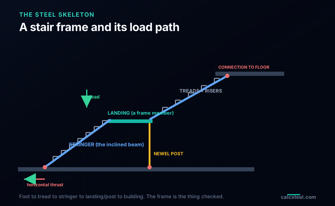
A metal stair frame is a small space frame with a specific job: carry a moving crowd down a steep line and hand the load, vertical and horizontal, back to the building. Name the parts before tracing the force through them.
- Two stringers, the inclined beams that run the full flight, one under each edge of the treads.
- Treads and closed risers, the steps: the tread you stand on, the riser closing the face. Together they span across the flight, stringer to stringer.
- The intermediate landing and its beam, a horizontal platform partway up. When present it props the stringers and breaks the span, and its beam is a real structural member.
- The newel or support posts, the columns that carry the landing and the flight ends down, and that resist lateral load.
- The connections to the two floors, top and bottom, where the flight lands and where thrust is either taken or released.
Now the load path, one footfall at a time. A foot lands on a tread. The tread spans the 1.20 m width and delivers its load to the two stringers as a line of reactions, which smear into a uniform load per metre on each stringer. Each stringer runs the incline and carries that load to its supports: either straight to the two floors, or to an intermediate landing partway up. The landing beam collects the propped stringer reaction and carries it sideways to the posts or into the building. And the whole assembly has one more duty a floor beam never has: it must return a horizontal reaction, plus any guardrail or seismic lateral load, back to the structure. That last sentence is the entire difference between a stair and a pair of beams.
The criterion behind the code: serviceability and stability, not strength
Put the two numbers side by side and the argument is over before it starts. On the worked flight, bending utilisation is 34 percent and the live deflection is 88.2 percent of the L/360 limit. Strength has a two-thirds margin. Deflection has barely an eighth. The section is not chosen by the moment, it is chosen by how far it sags.
This is not an accident of one flight, it is what codes do to stairs on purpose. A stair is light, steep and lively, so the governing clauses are the serviceability and stability ones: a deflection limit (L/360, and tighter where feel matters), a lateral and guardrail load path, and a vibration check. Strength is the easy gate. Every one of those governing checks is a property of the frame: the deflection depends on the span you chose to give the stringer, the sway depends on how you framed the supports, the frequency depends on both. You cannot pass them by upsizing a member in isolation. You pass them by deciding the frame.
So we run the check the way the code means it. Size the flight, watch strength pass and deflection govern, then make the two frame decisions, a landing or a deeper stringer, and see what each does to the numbers.
The worked stair frame
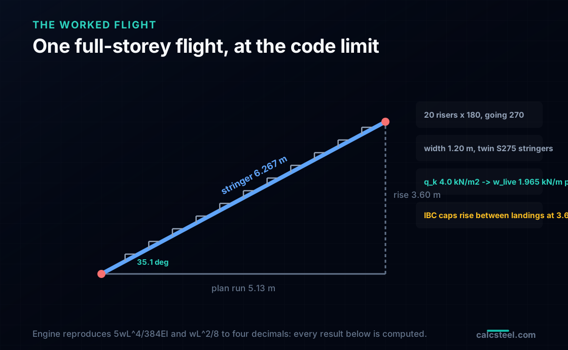
The stair: one straight flight, floor to floor. Rise H = 3.60 m, which sits right at the IBC limit on vertical rise between landings (12 ft = 3.658 m), so this flight is as tall as the code lets a single unbroken run be. Twenty risers at 180 mm, going 270 mm. With a 3.60 m rise and a 5.13 m plan run, the developed length the stringer actually spans is L = 6.267 m, at an incline of 35.1 degrees. Clear width 1.20 m, twin S275 stringers, each taking a 0.60 m tributary.
The load, per stringer, resolved along the slope. With code imposed load q_k = 4.0 kN/m2, the live line load is w_live = q_k x 0.60 x cos(35.1) = 1.965 kN/m. Dead load is w_dead = 0.48 kN/m (stringer self weight 0.19 kN/m plus a tread allowance). Their sum, w = 1.965 + 0.48 = 2.445 kN/m, is what bends the stringer.
Why trust the results. Before the stair, the CalcSteel FEM engine is calibrated against closed form on a plain beam: simply supported, span 4.0 m, UDL 10 kN/m, Ix = 1873 cm4. The engine returns delta = 8.8984 mm and M = 20.0 kN.m, reproducing 5 w L^4 / 384 E I and w L^2 / 8 to four decimals. The engine is not approximating the hand formula, it is landing on it. So every stair number below is the closed form, computed, not an estimate.
One flight: strength passes, deflection governs
Scheme A: one clean flight, no landing, IPE 180 stringers (Ix 1285 cm4, Sx 143 cm3). Start with strength. The moment is M = w L^2 / 8 = 2.445 x 6.267^2 / 8 = 12.0 kN.m. The bending stress is sigma = M / Sx = 84 MPa against a factored capacity phi_b Fy = 0.90 x 275 = 247.5 MPa, a bending utilisation of 34 percent. Strength passes with two thirds of the section in reserve. If strength were the check, you would specify the IPE 180 and move on.
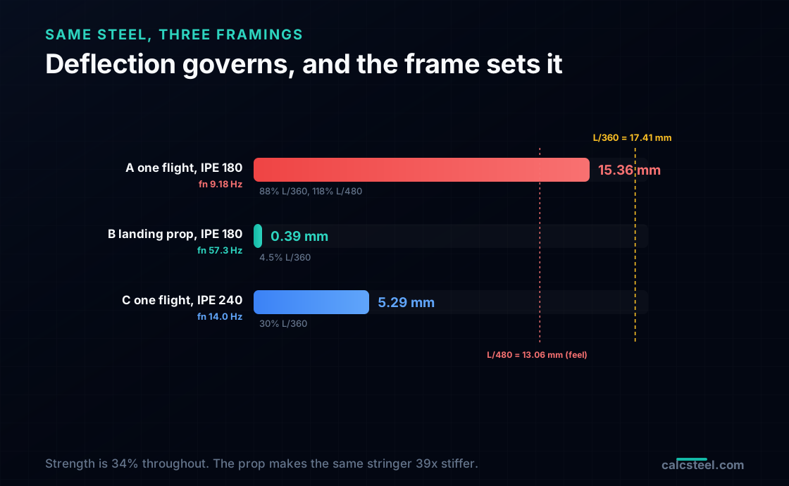
Now the deflection. Under the live load alone, delta = 5 w L^4 / 384 E I = 15.36 mm. The code screen L/360 = 6267/360 = 17.41 mm, so the flight is at 88.2 percent of L/360: it passes, barely. But the limit people actually feel on a stair is tighter. Against a comfort limit of L/480 = 13.06 mm, the same 15.36 mm is 117.6 percent: it fails. The stringer is bouncy exactly in the range a descending user notices.
The verdict is the thesis in one line: strength is a non-event, deflection governs, and it is a frame-length problem, not a section problem. At a full storey developed length of 6.267 m, the stringer is deflection-governed, and adding strength does nothing for stiffness. The three schemes that follow are the three honest ways out: break the span, deepen the section, or accept a longer flight and prove the dynamics.
Break the span: the landing is a frame member
Scheme B: the same IPE 180, but break the span. Insert an intermediate landing halfway up and it does something a bigger section cannot: it acts as a prop at midspan. The single 6.267 m flight becomes a two-span continuous stringer, each span 3.134 m. Deflection scales with the fourth power of span, so halving the span is not a factor of two, it is a landslide.
The numbers. Moment drops to M = 3.0 kN.m, utilisation to 8.5 percent. Live deflection falls to delta = 0.39 mm, just 4.5 percent of L/360. The identical steel is now 39 times stiffer. Nothing about the section changed, the frame changed. This is the single highest-leverage decision on the whole stair, and it lives entirely at frame level. A member check, run on either 3.134 m span in isolation, would never tell you the landing was the reason it works.
But the landing is not free structure. It is itself a frame member. That prop reaction has to go somewhere, and where it goes is the landing beam: it collects roughly 1.25 x w x span = 9.6 kN per stringer, about 19 kN total, and carries it sideways to its own posts or into the building. You did not delete the load, you rerouted it, and you added a beam and two supports to catch it. That trade, a landing and its supports against a lighter flight, is the decision the next scheme puts a price on, and it is invisible to every single-member check.
Or deepen the stringer: the steel-versus-landing trade
Scheme C: keep the clean flight, deepen the stringer. If a landing is unwelcome, because it costs headroom, plan length, and an extra framed bay, the other exit is to spend steel. Go from IPE 180 to IPE 240 (Ix 3733 cm4, Sx 311 cm3) and keep the single 6.267 m span.
Live deflection drops to 5.29 mm, 30.4 percent of L/360, comfortably inside even the tighter feel limit. The moment is 12.6 kN.m, utilisation 16.4 percent, strength never in question. It works, and it works on one flight. The price is weight: the IPE 240 self weight is 0.31 kN/m against 0.19 kN/m for the IPE 180, roughly sixty percent more stringer steel over the length of the flight.
So the real design question is not "what section." It is a frame trade: a landing (which buys enormous stiffness with the same light stringer, but costs headroom, plan area, an extra beam and two supports) against a heavier single flight (which keeps the geometry clean but spends steel and self weight). Neither answer is a member decision. Both are frame decisions, and the member check cannot see either one.
The load that sizes the frame, code by code
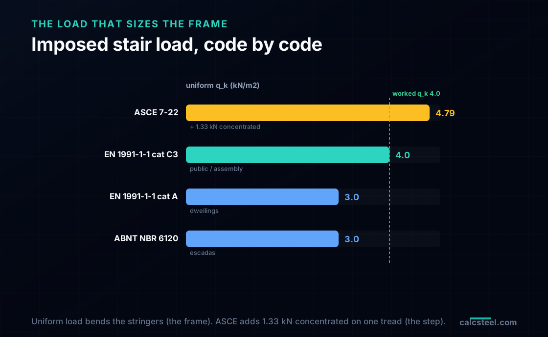
The frame is sized by the imposed load, and stairs get their own, higher line in every loading code, because that is where a crowd bunches and where a single step takes a person's full weight. Two loads, two jobs.
| Code | Uniform q_k | Concentrated load | Note |
|---|---|---|---|
| ASCE 7-22 | 4.79 kN/m2 (100 psf) | 1.33 kN (300 lb) | Highest uniform of the four; the point load sizes a single tread. |
| EN 1991-1-1 cat A | 3.0 kN/m2 | point load per code | Stairs in residential and similar occupancies. |
| EN 1991-1-1 cat C3 | 4.0 kN/m2 | point load per code | Areas liable to crowding; the value used on the worked flight. |
| ABNT NBR 6120 | 3.0 kN/m2 | point load per code | Brazilian imposed load for stairs and their access. |
The two loads do different work, and confusing them is a classic error. The uniform load bends the stringers and drives the deflection: it is the frame problem worked above, and the flight used q_k = 4.0 kN/m2 (Eurocode category C3, one step above the 3.0 kN/m2 that category A and the ABNT both use). The concentrated load does not size the frame at all, it sizes a single tread under one heavy step, wheel or point, which is the member check in the risers post. Run the crowd load through the frame and the point load through the step, do not average them into one.
The frame that is not there: sway and the mechanism
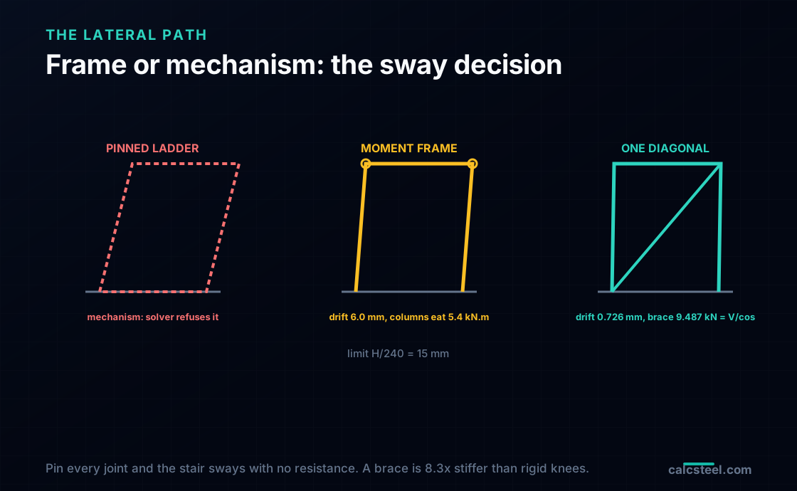
Turn the stair sideways and ask a different question: what stops it swaying. The support bent is two newel posts (HEB 160, 3.60 m tall) and a landing beam (IPE 200, 1.20 m) between them. The lateral demand is a lumped H = 3.0 kN at landing level, standing in for a guardrail line load of about 0.74 kN/m plus a notional and seismic lateral. Three ways to frame that bent give three completely different structures.
Pin every joint, no diagonal. Hinge the knees, hinge the bases, add no brace, and the shipping solver does not return a drift, it returns a mechanism: kinematic mechanism modes instead of a valid analysis. That is the software telling you the truth. A rectangle of pin-ended members is a linkage, not a structure, and it sways under any lateral load with no resistance at all. Plenty of built stairs are framed exactly this way by accident, and they lean on cladding or luck for stability.
Rigid knees, pinned bases: a moment frame. Make the beam-to-column joints moment connections and the bent stands up on its own. Under H = 3.0 kN the drift is 6.0 mm, 40 percent of the H/240 = 15 mm limit. It passes, and the price is that the columns carry the sway as bending: 5.4 kN.m each. The frame is stable because the members are working in bending to keep it square.
Pinned joints plus one diagonal: a braced frame. Go back to pinned knees, but add a single pin-ended diagonal (SHS 60x4). Drift collapses to 0.726 mm. The columns shed their bending to essentially zero, and the diagonal carries the whole story shear as almost pure tension. The engine gives the brace force as 9.487 kN, which equals the hand statics V / cos(theta) = 9.487 kN exactly, and a diagonal-axial-only closed form gives a drift of 0.635 mm, bracketing the FEM result. The braced bent is 8.3 times stiffer than the moment frame, for a fraction of the steel.
The lesson is not "brace everything." It is that a stair must have a deliberate lateral path, rigid knees or a diagonal, chosen on purpose. Pinned everywhere is not conservative, it is a mechanism. For the general principle, see the bracing check.
Where the frame delivers its load
An inclined flight has a habit floor beams do not: it pushes sideways. Resolve the support reactions of a beam tilted at 35.1 degrees and they are not vertical, the flight returns a horizontal thrust at each end. The connection to each floor either takes that thrust or the flight spreads and the treads pull apart at the seams. That single fact decides what kind of structure you built.
If the top and bottom connections are moment knees, or one base is fixed, the flight and its posts are a frame that resists its own sway and delivers the thrust into the floors. If every connection is a pin, the flight is a set of links with no lateral stability of its own, and it now depends entirely on the bracing from the previous section to stand. The connection detail is not a downstream afterthought, it is the choice between a frame and a mechanism, made at the ends.
There is a deliberate exception worth knowing. In seismic detailing, many stairs are intentionally isolated: one end is given a slip joint so that building drift can occur without dragging the stair, which would otherwise act as an unintended diagonal brace between floors and attract force it was never sized for. That isolation is correct, but it has a consequence: a stair that is slip-jointed at one end can no longer borrow the building's stiffness, so it must carry its own lateral stability internally, through its own braced or moment-framed bent. Free one degree of freedom and you inherit the duty to stabilise the rest.
Vibration: the check that is usually satisfied, until it is not
The last serviceability check is the one people skip because it usually passes, and then someday it does not. A stair is a spring with a person's mass on it, and its fundamental frequency matters because human footfall, especially a fast descent, is a rhythmic forcing function. AISC Design Guide 11 gives a simplified single degree of freedom estimate straight from the self-weight deflection: fn = 18 / sqrt(delta_dead in mm).
Run it on the three schemes. Scheme A: fn = 9.18 Hz. Scheme B, the propped flight: 57.3 Hz. Scheme C, the deep stringer: 14.0 Hz. The screen here is roughly 4 Hz, though stairs are commonly targeted higher, near 5 Hz, because descent is fast and its forcing harmonics reach up. All three clear it. That is the honest result, and it is not luck: once you controlled the deflection, the frequency followed, because both fall out of the same stiffness.
Two things are still true. First, the frame decision moves the frequency by six times, from 9 Hz to 57 Hz, the same span-breaking lever showing up in the dynamic check. Second, this comfortable outcome is specific to a normal, twin-stringer flight. On a slender feature stair, a mono-stringer, a very long single flight, an open architectural run, the frequency drops and the acceleration response to a descending crowd genuinely governs, which is exactly why DG11 and SCI P354 make vibration a check and not an afterthought. Do not assume, check: run your own flight below.
Try it: check your own flight
Model your own stringer as a beam in the embedded calculator and watch the same story unfold. Set the span to the developed length between supports (the along-slope length, not the plan run), pin both ends, and apply a UDL equal to your q_k times the stringer tributary width resolved along the slope. Read the deflection, compare it to L/360 and to the tighter L/480 that a stair user actually feels, and note the strength utilisation sitting far below it. Then halve the span, as if you dropped in a landing, and watch the deflection fall by roughly forty times. That one move, on screen, is the whole frame argument.
Max moment
45 kN·m
Max shear
30 kN
Max deflection
10.55 mm
= L/569
Bending stress σ
84.4 MPa
σ = M/Sx
Utilization
44.0%
NBR 8800 · δ ≤ L/250
Geometry & supports
Section
Ix 7999 cm⁴ · Sx 533 cm³ · 42.2 kg/m
Point loads (↓ positive)
None — add as many as you need.
Distributed loads (uniform or trapezoidal)
Model sketch
Diagrams — free PNG / SVG / CSV export, no watermark
Step-by-step — the calculation memory of YOUR beam
IPE 300 · L = 6 m · fy = 250 MPa
1. Reactions (equilibrium of the solved FEM model)
ΣFy = 0 · ΣM = 0
R_A = 30 kN · R_B = 30 kN
2. Peak shear (read from the SFD)
Vmax = |V(x)|max
Vmax = -30 kN @ x = 6 m
3. Peak moment (read from the BMD)
Mmax = |M(x)|max
Mmax = 45 kN·m @ x = 3 m
4. Peak deflection
EI = 15998 kN·m² (E = 200 GPa)
δmax = 10.55 mm @ x = 3 m = L/569
5. Elastic bending stress
σ = Mmax / Sx = 45.00 × 10³ / 533.3
σ = 84.4 MPa
6. Bending check — both codes, side by side
NBR 8800: σ ≤ fy/1.10 = 227.3 MPa · AISC 360: σ ≤ 0.90·fy = 225 MPa
NBR 37.1% PASS · AISC 37.5% PASS
7. Deflection check (serviceability — code-independent)
δ ≤ L/250 = 24 mm
10.55 mm / 24 mm = 44.0% PASS
Recomputed live from the current inputs by the direct-stiffness FEM engine — change any load and every step updates. Reproduce it by hand with the formulas in the sections below.
Lightest catalog profiles that pass (974 flexural candidates · NBR 8800)
| Profile | Std | Weight | Total steel | σ util | δ util | |
|---|---|---|---|---|---|---|
| W310x21 | AISC | 21 kg/m | 126 kg | 83% | 98% | |
| VS 300x23 | BR | 22.6 kg/m | 136 kg | 71% | 84% | |
| U 300x90x6.3 | BR | 23.1 kg/m | 139 kg | 82% | 98% | |
| U 300x100x6.3 | BR | 24.1 kg/m | 145 kg | 77% | 91% | |
| VS 250x25 | BR | 24.6 kg/m | 148 kg | 70% | 100% |
Elastic bending (σ = M/Sx vs fy/γa1, γa1 = 1.10 — NBR 8800) + deflection screening of the full flexural catalog. Lateral-torsional buckling, shear and local buckling are NOT checked here — run the full NBR 8800 / AISC 360 verification in the 3D editor.
Five ways a metal stair frame goes wrong
- Sizing for strength only. On the worked flight strength sits at 34 percent while deflection reaches 88.2 percent of L/360, so passing the moment check has still not chosen the section.
- Treating the intermediate landing as trim. It is a frame member that collects about 19 kN of prop reaction and carries it to its own supports, and forgetting to frame it means the stringer is propped on nothing.
- Pinning every joint with no lateral path. A bent of pin-ended members is a mechanism, not a stiff frame, and the solver returns kinematic modes rather than a drift.
- Ignoring the horizontal thrust. An inclined flight returns a horizontal reaction to each floor, and a connection that cannot take it lets the flight spread.
- Assuming vibration is automatic. It usually is once deflection is controlled, but on a slender feature stair the acceleration response to a fast descent governs, which is why it is a required check.
Key takeaways
- On the worked flight strength is a non-event at 34 percent utilisation while live deflection governs at 88.2 percent of L/360, so the stringer is chosen by stiffness, not by moment.
- The intermediate landing is a frame member, not trim: breaking the 6.267 m span into two makes the identical IPE 180 steel 39 times stiffer (0.39 mm against 15.36 mm) while it collects about 19 kN of prop reaction.
- Keeping one clean flight means spending steel instead, an IPE 240 at 5.29 mm and 0.31 kN/m against the IPE 180 at 0.19 kN/m: the honest landing-versus-weight trade.
- A stair with every joint pinned is a mechanism and needs a deliberate lateral path: a moment frame drifts 6.0 mm, a single diagonal drifts 0.726 mm and carries the story shear as V / cos(theta) = 9.487 kN.
- Vibration is usually satisfied once deflection is controlled (all three schemes clear the 4 to 5 Hz screen, fn 9.18 to 57.3 Hz), but it genuinely governs a slender feature stair, which is why DG11 keeps it a check.
Sources
- 1.International Building Code (IBC) 2021, Section 1011 Stairways (riser and tread limits, dimensional uniformity, and the 12 ft = 3.658 m maximum vertical rise between landings)
- 2.ASCE/SEI 7-22, Minimum Design Loads and Associated Criteria for Buildings and Other Structures (Table 4.3-1, stair uniform 100 psf and 300 lb concentrated live loads)
- 3.AISC Design Guide 34, Steel-Framed Stairway Design
- 4.AISC Design Guide 11, Vibrations of Steel-Framed Structural Systems (fundamental frequency and stair vibration)
- 5.EN 1991-1-1:2002 Eurocode 1, imposed loads on stairs (Table 6.2), with EN 1993-1-1 for steel member design
- 6.SCI P354, Design of Floors for Vibration: A New Approach (stairs and human-induced vibration)
- 7.ABNT NBR 6120:2019 Acoes para o calculo de estruturas and NBR 9077:2001 Saidas de emergencia (stair loads and geometry)
Try CalcSteel for free
Model, analyze and design steel structures in your browser. No install, no signup.
Open the 3D editor