Fillet Weld Strength & Sizing per AISC 360
How to calculate fillet weld capacity per AISC 360-22 Chapter J2: throat area, electrode strength, minimum sizes and the directional strength increase, then an eccentric bracket group worked twice, by the elastic vector method and by the instantaneous centre of rotation.
Key takeaways
- A fillet weld is always checked on its throat: φr_nw = 0.75 × 0.60 × F_EXX × 0.707a, which is 1.227 kN/mm for an 8 mm E70XX leg.
- AISC 360-16 and later read Table J2.4 from the thinner part joined, not the thicker one. Older references have it the other way round.
- Past a = 0.587t on A36 (0.660t on A992) the plate ruptures before the weld does, so a larger fillet buys nothing.
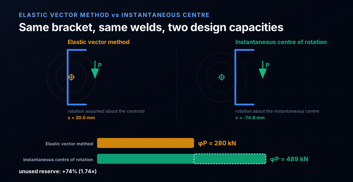
- For an eccentric group the elastic vector method is safe but low: on the worked bracket it returns 280 kN against 489 kN from the instantaneous centre method.
- The ICR coefficient C already contains the directional strength increase. Applying the increase on top of it double counts by up to 50%.
What is a fillet weld and how does it work?
A fillet weld is a triangular cross-section weld deposited in the corner formed by two surfaces meeting at approximately 90°. It is the most common weld type in structural steel: roughly 80% of all structural welds are fillet welds.
Fillet welds resist forces by shearing through the weld throat, the minimum cross-section through the weld. For an equal-leg fillet weld with leg size a, the throat dimension is:
t_e = 0.707 × a
This comes from the geometry of a 45° right triangle: the shortest distance from the root to the face is a × cos(45°) = 0.707a.
The weld capacity depends on:
- The throat area (throat × length)
- The electrode strength (F_EXX)
- The angle of loading relative to the weld axis
Fillet welds are always assumed to fail by shearing through the throat, regardless of the load direction. AISC J2.4 provides the design equations.

How do you calculate fillet weld capacity per AISC 360?
The nominal strength of a fillet weld per unit length is:
R_nw = 0.60 × F_EXX × t_e × L
Where:
- F_EXX = electrode classification strength (482 MPa for E70XX, the standard structural electrode)
- t_e = effective throat = 0.707 × a
- L = weld length
- φ = 0.75 (LRFD) or Ω = 2.00 (ASD)
Capacity per mm of weld length
For an 8 mm fillet weld with E70XX, the LRFD design capacity per mm of weld length is:
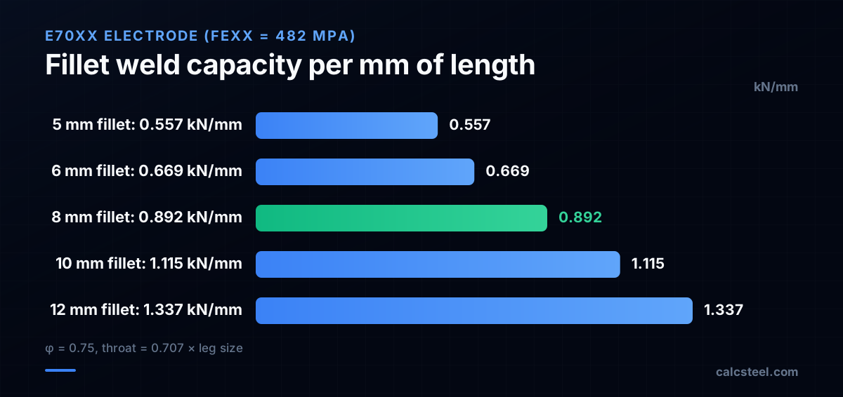
φr_nw = φ × 0.60 × F_EXX × (0.707 × a) = 0.75 × 0.60 × 482 × 0.707 × 8 = 1227 N/mm = 1.227 kN/mm.
The capacity scales linearly with the leg size, so a larger leg gives proportionally more capacity per mm of weld, and the chart plots φr_nw for common leg sizes.
CalcSteel tip: the connection engine computes weld capacity automatically for every weld group, accounting for load angle and directional strength increase.
What is the minimum and maximum fillet weld size?
AISC J2.2b specifies minimum fillet weld sizes to prevent cracking from the rapid cooling of a thin weld on heavy base metal. In AISC 360-16 and 360-22 the table is read from the thinner part joined. Editions up to 360-10 read it from the thicker part, which is why older references and older spreadsheets disagree with a current one on the same joint:
| Thinner part joined | Min fillet weld size |
|---|---|
| t ≤ 6 mm | 3 mm |
| 6 < t ≤ 13 mm | 5 mm |
| 13 < t ≤ 19 mm | 6 mm |
| t > 19 mm | 8 mm |
The minimum size never needs to exceed the thickness of the thinner part joined.
Maximum fillet weld size
Along edges of material less than 6 mm thick: weld size ≤ material thickness. Along edges of material 6 mm or thicker: weld size ≤ material thickness − 2 mm.
This ensures the weld does not overhang the plate edge, which would create a stress concentration.
Minimum weld length
The minimum effective length of a fillet weld designed on strength is 4 times its leg size (4a). Below that, start and stop effects mean the weld cannot develop its full throat. The extra floor of 38 mm (1½ in.) applies to the segments of intermittent fillet welding, not to a continuous run.
Practical sizing
In practice, 6 mm and 8 mm fillet welds are the most common sizes:
- 6 mm: the default for most connections (shop and field)
- 8 mm: for heavier connections or when calculation requires more capacity
- 5 mm: minimum for plates over 6 mm thick
- 10 mm and above: expensive to deposit (multiple passes required); consider using CJP welds instead

What is the directional strength increase for fillet welds?
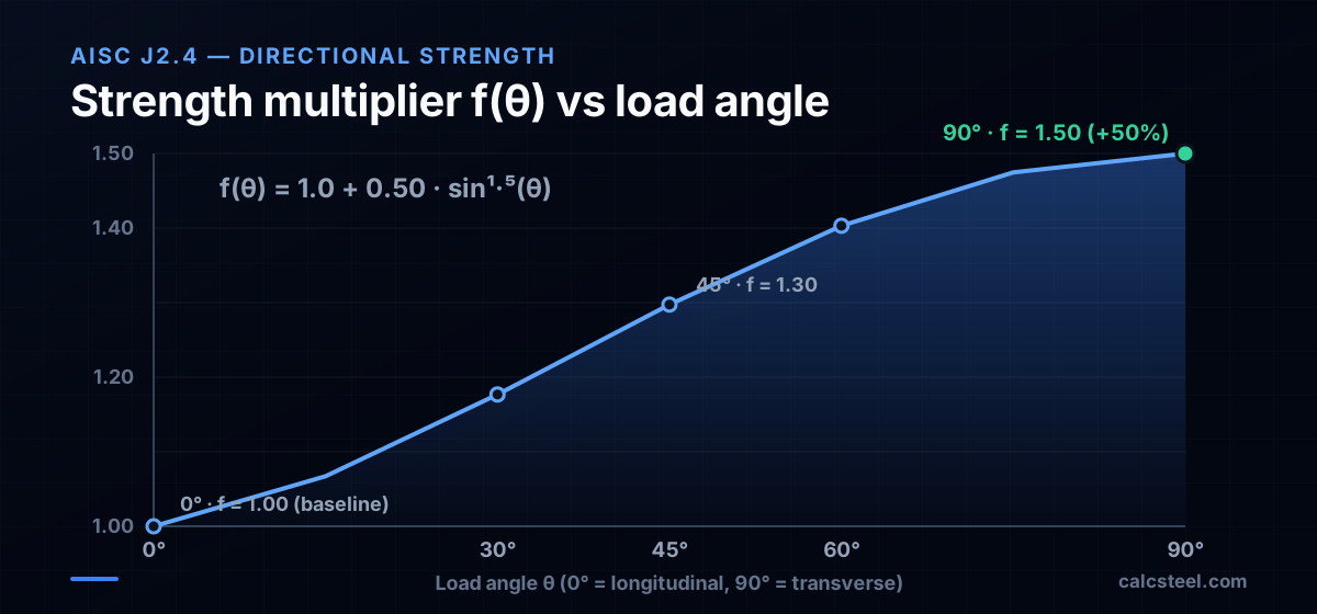
AISC J2.4 allows a strength increase when the load acts transverse to the weld axis. A transversely loaded fillet weld is approximately 50% stronger than a longitudinally loaded one because the failure plane shifts.
The directional strength factor is:
f(θ) = (1.0 + 0.50 × sin^1.5(θ))
Where θ is the angle between the load direction and the weld longitudinal axis.
| Load angle θ | f(θ) | Strength increase |
|---|---|---|
| 0° (longitudinal) | 1.00 | Baseline |
| 30° | 1.18 | +18% |
| 45° | 1.30 | +30% |
| 60° | 1.40 | +40% |
| 90° (transverse) | 1.50 | +50% |
When to use the directional increase
The directional strength increase is optional: you can always use the baseline value (θ = 0°) for conservative design. Use the increase when:
- The connection is tight on weld capacity and adding length is difficult
- All welds in the group are loaded at the same angle (e.g., a pair of transverse fillet welds on a shear tab)
Do NOT use the increase for weld groups with mixed orientations without also checking the weld group instantaneous center of rotation (ICR method).
Weld groups with mixed orientation
For an L-shaped or C-shaped weld pattern (longitudinal + transverse welds), AISC allows two approaches:
- Use the baseline strength (no directional increase) for all welds (simple and conservative)
- Use the ICR method, which accounts for deformation compatibility between welds loaded at different angles
How do you design a fillet weld for a shear connection?
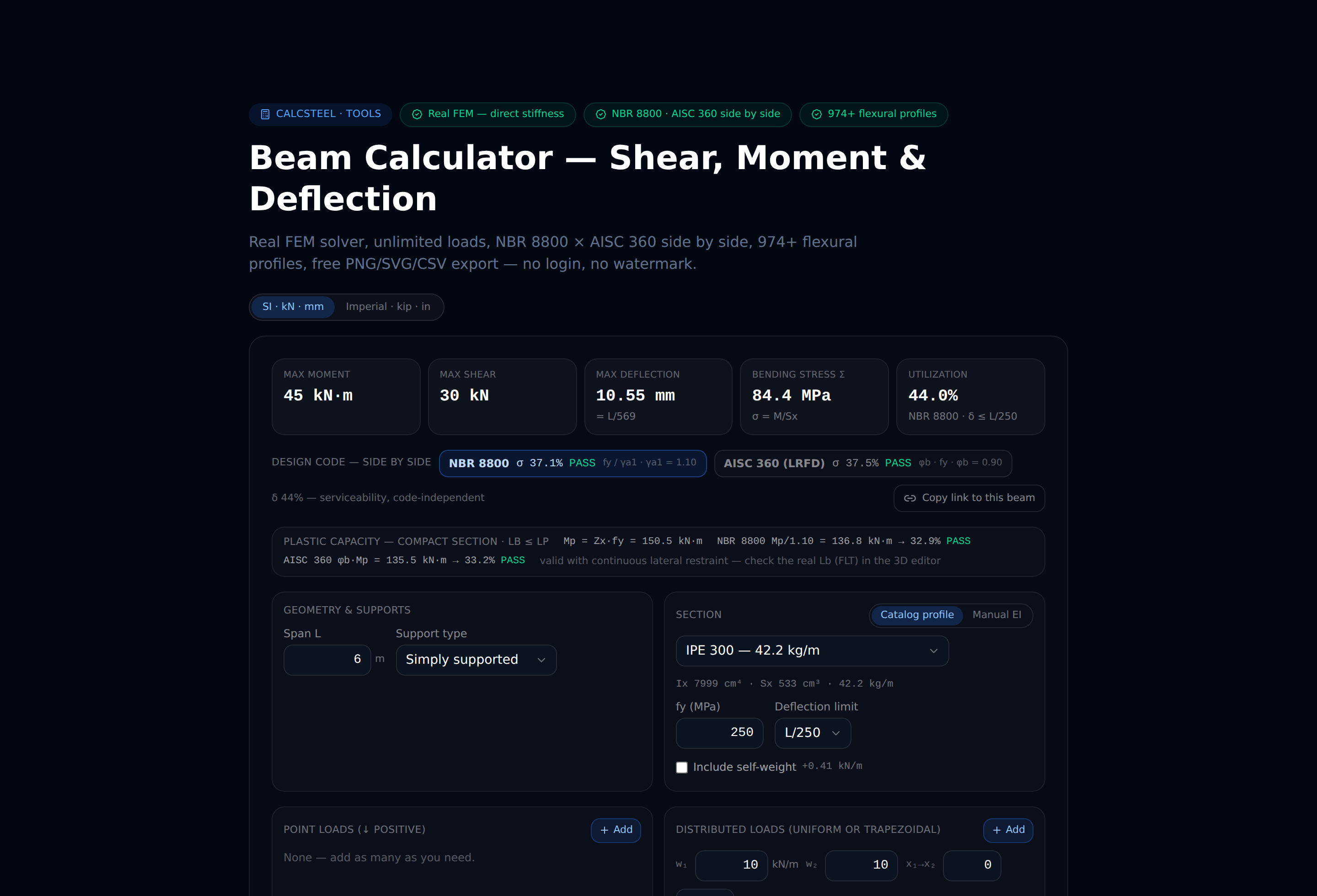
The most common application of fillet welds is in shear connections: shear tabs, clip angles, and end plates welded to beams or columns. These welded joints are a direct alternative to bolted connections, and choosing between them follows the same logic as picking a shear versus moment connection. Before sizing the weld you need the design force, so find the factored beam reaction with our free calculator (no sign-up required).
Example: shear tab welded to a column flange
Given:
- Beam reaction: V_u = 180 kN (factored)
- Shear tab: 10 mm thick, 250 mm long, A36 steel
- Column: W310×97, A992 steel (flange t_f = 15.4 mm)
- Weld: E70XX electrode
Step 1: required weld size
The tab is welded to the column flange with fillet welds on both sides. Total weld length = 2 × 250 = 500 mm.
Required capacity per mm: q = V_u / L_total = 180 / 500 = 0.36 kN/mm
From the capacity chart, a 5 mm fillet gives 0.767 kN/mm, comfortably above 0.36.
Step 2: check the code minimum
AISC 360-22 reads Table J2.4 from the thinner part joined. Here that is the 10 mm tab, not the 15.4 mm flange, so the minimum is 5 mm. (Read the old way, from the thicker part, the 15.4 mm flange would have asked for 6 mm. Same joint, different edition, different answer.)
So 5 mm satisfies both strength and the minimum:
φR_n = 0.767 kN/mm × 500 mm = 383 kN against 180 kN, a ratio of 0.47.
Step 3: check the base metal
The weld cannot outrun the plate it sits on. Shear rupture of the tab, per J4.2:
φR_n = 0.75 × 0.60 × 400 MPa × 10 mm × 250 mm = 450 kN
450 kN is above the 383 kN of weld metal, so the weld governs and the 5 mm leg stands. On a thinner tab it would not: see the crossing thicknesses below.
Step 4: check weld returns
For welds terminating at the ends of the shear tab, provide a weld return of at least 2 times the weld size (2 × 5 = 10 mm) around the corner. This keeps the stress concentration off the weld end.
What CalcSteel returns here: 8 mm, not 5 mm. Strength and the J2.4 minimum are satisfied at 5 mm, but the engine also applies the 5/8·t rule that develops the tab (5/8 × 10 = 6.25 mm), then rounds up to the next leg the shop runs. Strength is the floor, detailing practice sets the answer.
When does the base metal govern instead of the weld?
AISC 360 J2.4 sizes the weld metal. It says nothing about whether the plate behind the weld can deliver the force. That is J4.2, shear rupture of the base metal, and on a thin plate it is the check that decides.
Put the two on the same ruler, per millimetre of joint, for a plate with fillet welds on both sides:
- Weld metal: φr_w = 2 × 0.75 × 0.60 × F_EXX × 0.707a
- Base metal: φr_BM = 0.75 × 0.60 × F_u × t
Set them equal and you get the leg size at which the plate takes over:
- A36 plate (F_u = 400 MPa): a = 0.587 t
- A992 (F_u = 450 MPa): a = 0.660 t
The plate each leg size needs
| Fillet leg (both sides) | Capacity | Plate that develops it (A36) |
|---|---|---|
| 5 mm | 1.53 kN/mm | t ≥ 8.5 mm |
| 6 mm | 1.84 kN/mm | t ≥ 10.2 mm |
| 8 mm | 2.45 kN/mm | t ≥ 13.6 mm |
| 10 mm | 3.07 kN/mm | t ≥ 17.0 mm |
Below the crossing thickness a bigger fillet buys nothing: the plate ruptures first, and the extra weld metal is specified, deposited, paid for and wasted.
Why the shop rule is 5/8 of the thickness
The AISC Manual Part 10 rule of thumb, a = 5/8·t, lands exactly between the two crossings: 0.625 is more than the 0.587 an A36 plate needs and less than the 0.660 an A992 plate needs. On A36 it develops the plate with margin. On A992 it does not quite get there, so a joint that has to develop the full plate needs the check rather than the rule.
CalcSteel tip: the engine applies this rule as pernaQueDesenvolve = 0.625·t and then snaps the result up to a leg the shop actually runs: 3, 4, 5, 6, 8, 10 or 12 mm.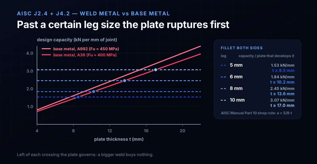
How do you analyze a weld group under eccentric load?
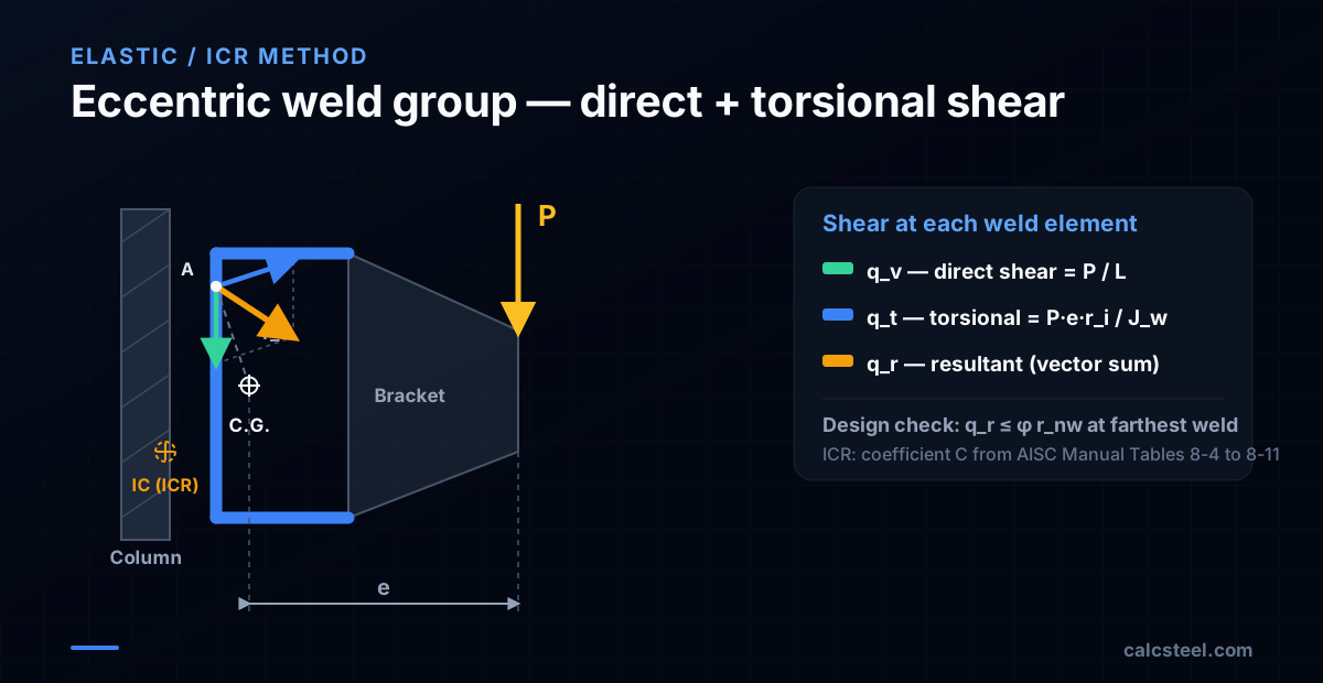
When the load does not pass through the centroid of the weld group, the welds experience both direct shear and torsional shear. The classic example is a bracket welded to a column.
Elastic method (simplified)
- Find the centroid of the weld group (treat welds as line elements)
- Direct shear: q_v = P / L_total (distributed equally to all welds)
- Torsional shear: q_t = (P × e × r_i) / J_w, where e is the eccentricity, r_i is the distance from each weld element to the centroid, and J_w is the polar moment of inertia of the weld group
- Combine vectorially: q_total = √(q_v² + q_t² + 2q_v × q_t × cos α), where α is the angle between the direct and torsional components
- Check: q_total ≤ φ × r_nw
Instantaneous Center of Rotation (ICR) method
The AISC Manual Tables 8-4 through 8-11 provide coefficient C for common weld patterns. The design strength is:
φR_n = C × C₁ × D × L
Where C is from the table (depends on l/a ratio and eccentricity angle), C₁ adjusts for electrode type (1.0 for E70XX), D is the number of sixteenths in the weld size, and L is the weld length.
The ICR method is more accurate than the elastic method because it accounts for the non-uniform deformation of welds in the group.
How do you compute Jw, the polar moment of a weld group?
Every eccentric weld group calculation starts from the same three section properties, computed with the welds treated as lines of unit width. The throat is applied at the end, so it drops out of the geometry.
The three steps
- Centroid: x̄ = Σ(L_i · x_i) / ΣL_i, and the same for ȳ.
- Second moments about that centroid. A segment of length L running parallel to the axis contributes L·d². A segment perpendicular to it contributes L³/12 + L·d², where d is the distance from the segment's own midpoint to the group centroid.
- Polar moment: J_w = I_x + I_y.
The bracket group, step by step
Take a C-shaped group: one 300 mm vertical weld on the column face, plus 100 mm horizontal welds at the top and at the bottom. Total length L = 500 mm.
x̄ = (300 × 0 + 2 × 100 × 50) / 500 = 20 mm from the column face, and ȳ = 150 mm by symmetry.
I_x = 300³/12 + 2 × 100 × 150² = 2.25×10⁶ + 4.50×10⁶ = 6.75×10⁶ mm³
I_y = 300 × 20² + 2 × (100³/12 + 100 × 30²) = 0.120×10⁶ + 0.347×10⁶ = 0.467×10⁶ mm³
J_w = 6.75×10⁶ + 0.467×10⁶ = 7.22×10⁶ mm³
Watch the units: mm³, not mm⁴. Leaving the throat out of the geometry costs one power of length, and it comes back when you multiply by the capacity per millimetre.
The arithmetic is the same one you run on any built-up section, only with lines instead of rectangles. The calculator below does the I_x and I_y part for a shape you define, which is the step most people get wrong when the horizontal legs are short.
Formula — hover a variable to highlight it on the drawing
Ix = [ b·h³ − (b − tw)·hw³ ] / 12= 1,845.6 cm⁴(hw = h − 2·tf)
Iy = [ 2·tf·b³ + hw·tw³ ] / 12= 141.9 cm⁴
Root fillets are neglected — rolled-section tables run 1–5% higher on Ix.
Parallel-axis theorem, live — Ix = Σ ( I₀ + A·d² )
| Part | A (cm²) | d (cm) | I₀ (cm⁴) | A·d² (cm⁴) | I₀ + A·d² (cm⁴) |
|---|---|---|---|---|---|
| Web | 10.25 | 0 | 286 | 0 | 286 |
| Flange (top) | 8.5 | 9.58 | 0.512 | 779.3 | 779.8 |
| Flange (bottom) | 8.5 | 9.58 | 0.512 | 779.3 | 779.8 |
| Σ = Ix | 287 | 1,558.6 | 1,845.6 |
Exact rectangle parts (web + two flanges) about the section centroid — the flange A·d² transfer terms are the whole story of the I-beam. Change any dimension above and watch the table re-derive.
Section properties
Moment of inertia Ix
1,845.6 cm⁴
1.846 × 10⁷ mm⁴
Moment of inertia Iy
141.9 cm⁴
1.419 × 10⁶ mm⁴
Area A
27.25 cm²
Mass
21.39 kg/m
Section modulus Sx
184.6 cm³
Section modulus Sy
28.39 cm³
Plastic modulus Zx
209.7 cm³
Plastic modulus Zy
43.93 cm³
Radius of gyration rx
8.23 cm
Radius of gyration ry
2.28 cm
Centroid x̄ (from left)
50 mm
Centroid ȳ (from bottom)
100 mm
Local slenderness — NBR 8800 / AISC 360 fingerprint
Flange
λ = b / 2·tf = 5.88
λp = 10.75 · λr = 28.28
Web
λ = hw / tw = 32.68
λp = 106.3 · λr = 161.2
Flexure limits per AISC 360 Table B4.1b (≈ NBR 8800 Annex F), fy = 250 MPa, E = 200 GPa — λp/λr scale with √(E/fy). Compact sections reach the full plastic moment Mp = Z·fy; non-compact and slender elements are capped by local buckling.
Closest standard profiles — matched by Ix against 876 real catalog sections
Ix = 1,845.6 cm⁴ (-0.0%)
Iy = 141.9 cm⁴ (-0.0%)
21.39 kg/mlightest
Best match — design checks
Ix = 1,844.2 cm⁴ (-0.1%)
Iy = 902.5 cm⁴ (+535.8%)
34.19 kg/m#2 by weight
Design checks
Ix = 1,838.7 cm⁴ (-0.4%)
Iy = 1,838.7 cm⁴ (+1195.4%)
43.96 kg/m#3 by weight
Design checks
Same 1,309-profile database that powers the CalcSteel 3D editor and profile pages — ABNT cold-formed (Ue, U, rounds), AISC (W, HSS, L, Pipe), European (IPE, HEA, HEB, HEM, UPN) and Indian (ISMB/ISMC) series. Opening a match carries your custom section along as the comparison baseline.
Worked example: a bracket weld group by the elastic vector method
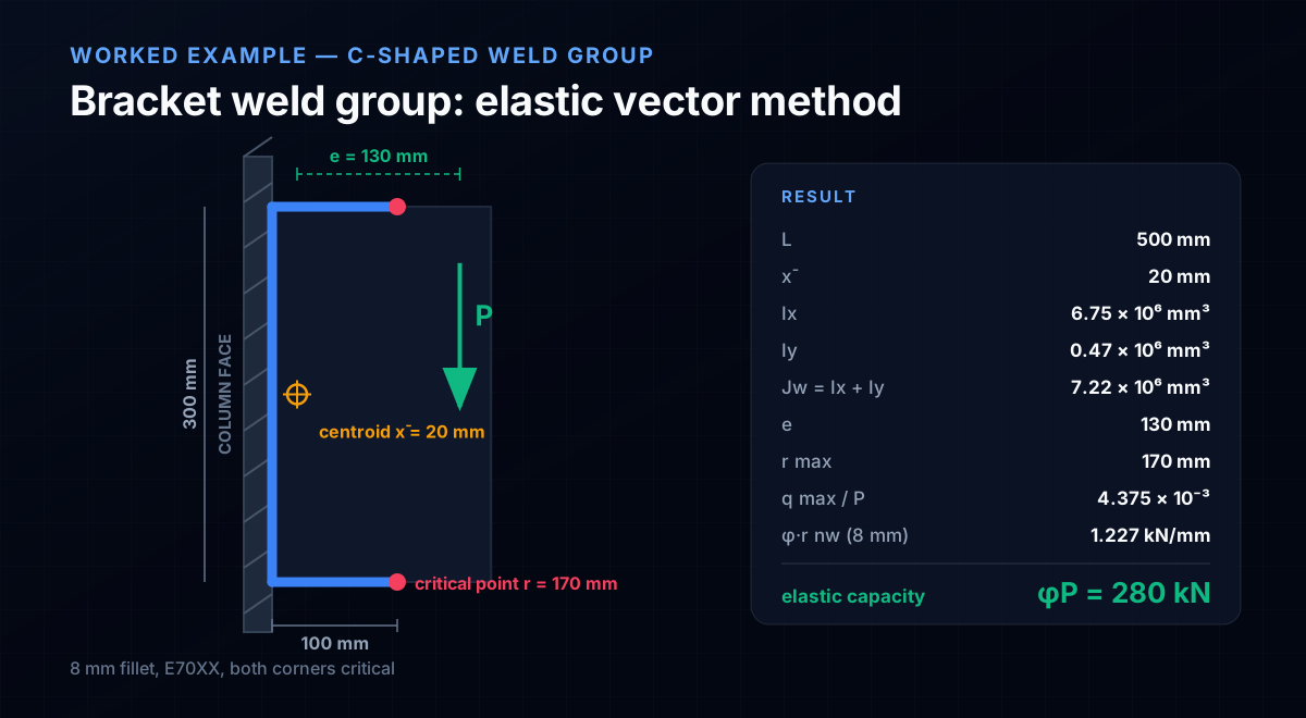
Same C-shaped group, now with 8 mm fillet welds and E70XX electrodes. The load P is vertical and lands 150 mm from the column face, so the eccentricity measured from the group centroid is e = 150 − 20 = 130 mm.
Step 1: find the critical point
The elastic method assumes the bracket plate is rigid and rotates about the weld group centroid, so stress grows with distance from it. The farthest points are the two outer corners, at r_x = 80 mm and r_y = ±150 mm:
r = √(80² + 150²) = 170 mm
Step 2: direct shear
q_v = P / L = P / 500 = 2.000×10⁻³ P, acting vertically on every element.
Step 3: torsional shear
The torque about the centroid is M = P·e = 130P. At the critical corner it splits into two components:
- horizontal: q_tx = M·r_y / J_w = (130 × 150 / 7.217×10⁶) P = 2.702×10⁻³ P
- vertical: q_ty = M·r_x / J_w = (130 × 80 / 7.217×10⁶) P = 1.441×10⁻³ P
Step 4: combine, then check
The vertical components add:
q_y = 2.000×10⁻³ P + 1.441×10⁻³ P = 3.441×10⁻³ P
q_r = √(2.702² + 3.441²) × 10⁻³ P = 4.375×10⁻³ P
An 8 mm E70XX fillet carries φr_nw = 1.227 kN/mm at the baseline load angle, so:
P = 1.227 / (4.375×10⁻³) = 280 kN
Note that both outer corners reach that value at the same time. The direct shear is vertical, and the vertical component of the torsional shear has the same sign at the top corner and at the bottom one, so the group has no single worst weld. Only the horizontal component flips sign.
Why the elastic vector method underestimates a weld group
The elastic vector method makes one assumption the weld does not honour: that every element of the group sits at the same point on its own load-deformation curve. It does not, and AISC's design method is built around saying so.
A fillet weld element is not a linear spring
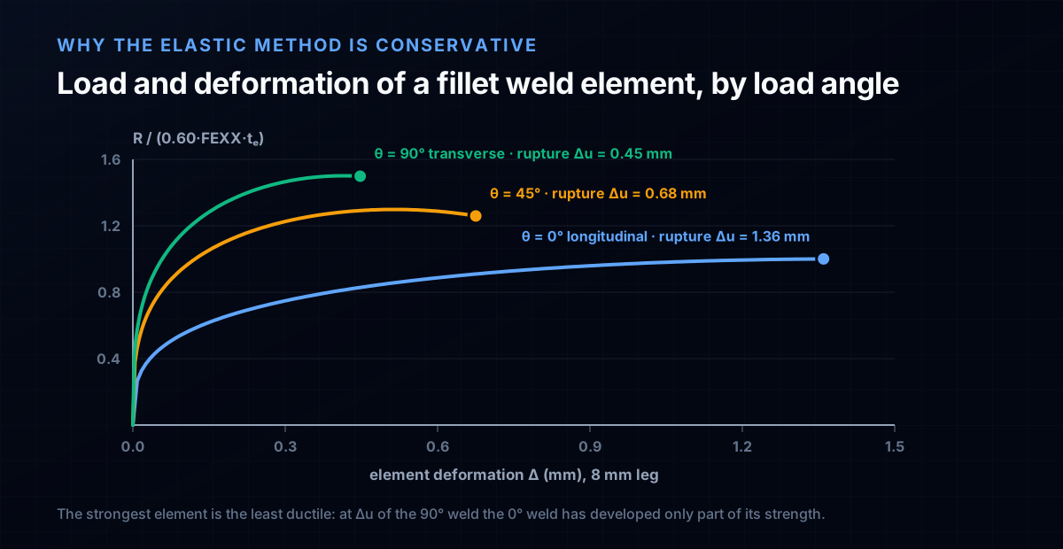
AISC Manual Part 8 models each element with a law that depends on the load angle θ (Lesik and Kennedy, 1990):
R(θ, Δ) = 0.60 F_EXX (1.0 + 0.50 sin^1.5 θ) [p(1.9 − 0.9p)]^0.3 A_we, with p = Δ/Δ_m
- Δ_m = 0.209 (θ + 2)^−0.32 · w, the deformation at peak load
- Δ_u = 1.087 (θ + 6)^−0.65 · w, capped at 0.17w, the deformation at rupture
The strongest element is the least ductile
Put an 8 mm leg through those two equations and the conflict inside a mixed group is immediate:
| Load angle θ | Peak strength factor | Rupture deformation Δu |
|---|---|---|
| 0° (longitudinal) | 1.00 | 1.36 mm |
| 45° | 1.30 | 0.68 mm |
| 90° (transverse) | 1.50 | 0.45 mm |
A transverse element is 50% stronger and it ruptures at a third of the deformation a longitudinal element tolerates. In a group with mixed orientation the two peaks never coincide: by the time the longitudinal weld is fully developed the transverse weld has already failed, and while the transverse weld is at its peak the longitudinal one is carrying a fraction of what it could.
What each method does about it
The elastic vector method steps around the problem. It drops the directional increase entirely, uses the baseline θ = 0 strength for every element, and checks the single most stressed point. That is safe, and it is exactly why the answer comes out low.
The instantaneous centre method faces it. It looks for the one centre of rotation at which the element forces, each read off its own curve at its own deformation, balance the applied load. Nothing is assumed to happen simultaneously.
Worked example: the same bracket by the instantaneous centre method
Same bracket, same 8 mm welds, same 130 mm eccentricity. The only thing that changes is the assumption about how the plate moves.
The procedure
- Assume a position for the instantaneous centre (IC). For a vertical load on a group symmetric about a horizontal axis, it sits on that axis, on the opposite side of the group from the load.
- Scale the deformations. Every element rotates about the IC, so its deformation is proportional to its distance r_i from it. Anchor them on the element that runs out first, the one with the smallest Δ_u/r ratio: Δ_i = r_i · (Δ_u,crit / r_crit).
- Read each element's angle. Its force is perpendicular to its own r_i, and the angle between that force and the weld axis is θ_i, which fixes Δ_m, Δ_u and the directional factor for that element alone.
- Sum and iterate. Take R_i off the curve, then move the IC until ΣR_x = 0, ΣR_y = P, and the moment of all the R_i about the IC equals P times its distance to the load line.
The answer
For this bracket the equilibrium position is 75 mm beyond the column face, on the far side of the welds, which is 95 mm from the group centroid. Solving there gives:
φP = 489 kN, against 280 kN from the elastic method on the identical joint.
Two things open that gap, and redistribution is the larger. Hold the directional increase out of the ICR solution, and the bracket still climbs from 280 kN to 384 kN: a factor of 1.37, from redistribution alone. Crediting the directional increase on top, which approaches 1.50 on the near-transverse elements and which the elastic method waives entirely, carries 384 kN to 489 kN, a further 1.27. Read the 1.74 as those two factors multiplied, not as redistribution on its own.
Where the AISC tables come in
You are not expected to run that iteration by hand. AISC Manual Part 8 tabulates its result as a coefficient C for the common patterns, so that:
φR_n = φ · C · C₁ · D · l
with D the weld size in sixteenths of an inch, l the length of the vertical weld, and C₁ = 1.0 for E70XX. Tables 8-4 through 8-11 cover the usual geometries, including this C shape. The coefficient already contains the directional increase, which is the reason for the last item in the next section.
What are common mistakes in fillet weld design?
1. Using the wrong throat for unequal-leg welds
For an unequal-leg fillet weld (e.g., 8×12 mm legs), the throat is NOT 0.707 × average. It is the shortest distance from the root to the weld face, which depends on the actual leg dimensions and root profile. For standard equal-leg welds, 0.707a is correct.
2. Ignoring weld access
A weld designed on paper may be impossible to execute in the field if the welder cannot access the joint. Common issues: welds inside closed HSS sections, welds behind other members, welds requiring overhead position in difficult locations.
3. Specifying oversized welds
A 12 mm fillet weld requires multiple passes and is expensive to deposit. Two passes of 6 mm fillet on each side often provide more total capacity at lower cost than one heavy weld on one side.
4. Not checking the base metal
The weld strength may exceed the base metal strength. AISC J2.4 requires checking that the base metal can also resist the weld forces: φR_n = φ × 0.60 × F_y × t × L for shear on the base metal.
5. Forgetting shear lag in welded tension connections
When a member is welded by only some of its elements (e.g., only one leg of an angle), the shear lag factor U reduces the effective area. This is a net section check, not a weld check, but it often governs.
6. Specifying E70XX when E80XX or higher is needed
For high-strength steels (F_y > 345 MPa), the weld metal must match or exceed the base metal strength. E70XX is adequate for A36 and A992, but not for A913 Grade 65 or higher.
7. Taking the ICR coefficient and the directional increase together
The coefficient C in AISC Manual Tables 8-4 through 8-11 is the output of the instantaneous centre iteration, and that iteration has already applied (1.0 + 0.50 sin^1.5 θ) to every element in the group. Multiplying C by the directional factor a second time double counts it and can overstate the group by up to 50%. Choose a method and stay inside it.
How does CalcSteel design fillet welds?
CalcSteel's connection engine sizes and checks fillet welds as part of every connection, from beam shear tabs to column base plates. It is worth being precise about what it does and does not solve.
Weld sizing
The leg comes from the thinner part of the joint, through three criteria at once: the Table J2.4 minimum, the 5/8·t rule that develops the part, and the J2.2b ceiling that stops the fillet eating the plate edge. The result is snapped up to a leg the shop runs (3, 4, 5, 6, 8, 10 or 12 mm).
For the 10 mm shear tab above against a 15.4 mm flange, the engine returns 8 mm: strength alone would take 5 mm, but 5/8 × 10 = 6.25 mm rounds up to the next commercial leg.
Weld metal and base metal on the same ruler
Both are computed, converted to the same stress per millimetre of joint, and the engine reports which one governs rather than only the utilisation. On a thin plate that is routinely the base metal.
Weld groups
Where the load angle is unambiguous, the engine applies the directional increase (a transverse flange plate weld carries the full 1.50), and for groups that mix longitudinal and transverse runs it takes the J2-6a / J2-6b envelope rather than adding peaks.
Eccentric weld groups are the honest limit. CalcSteel does have an instantaneous centre solver, benchmarked against AISC Manual Table 7-6, but it solves bolt groups. There is no ICR for welds in the engine today, so the models whose capacity depends on one (the welded seated angle, the welded purlin cleat) are declared out of scope in the catalogue instead of being approximated. Faking two vertical fillets as pure shear would overstate them by roughly 40%, which is the size of the coefficient that is missing.
Output
The connection detail drawing carries the weld type (fillet, CJP, PJP), the leg in mm, the length, the electrode class and the utilisation ratio, and all of it travels into the connection export for shop drawing preparation.
Sources
Try CalcSteel for free
Model, analyze and design steel structures in your browser. No install, no signup.
Open the 3D editor