Castellated and Cellular Beams: More Depth from the Same Weight, and the Checks It Adds
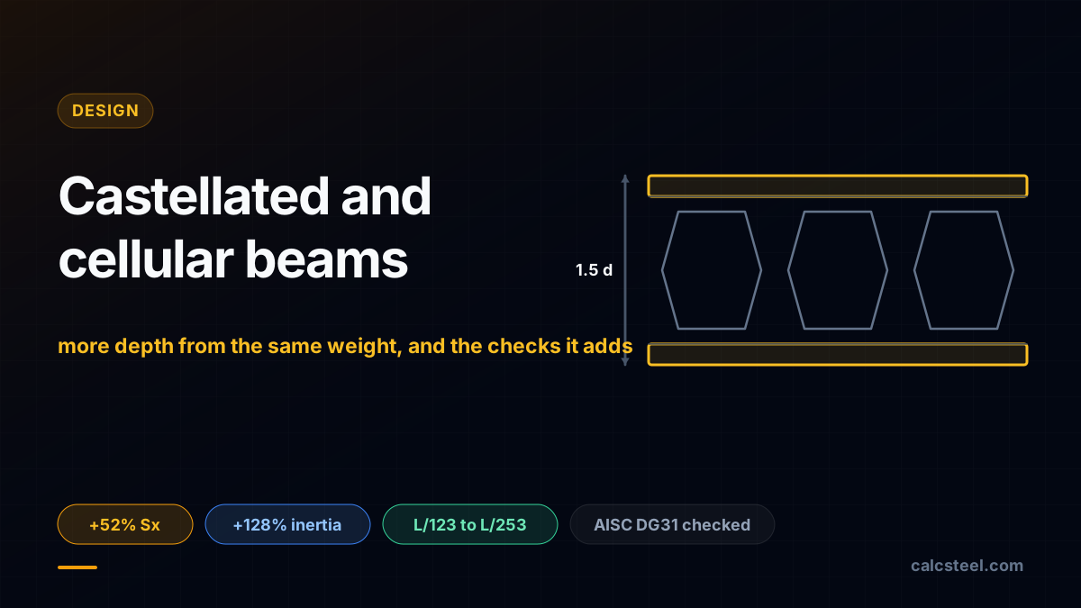
A castellated beam is not a deeper beam you bought. It is a rolled I section you cut along a zigzag, pulled apart by one tooth, and welded back together, so it stands about 50 percent taller at almost exactly the same weight per metre. Depth is where a beam keeps its stiffness and its moment capacity, so those same kilos suddenly reach further. On the real CalcSteel engine an IPE 400 that sags to L/123 over a 12 m span, and would be thrown out on deflection, is castellated to 600 mm and lands at L/253 with no extra steel. The catch is that the openings add checks a solid web never needed, and near the supports those checks, not the gross section, decide the beam. This guide runs the numbers and validates them against AISC Design Guide 31.
Key takeaways
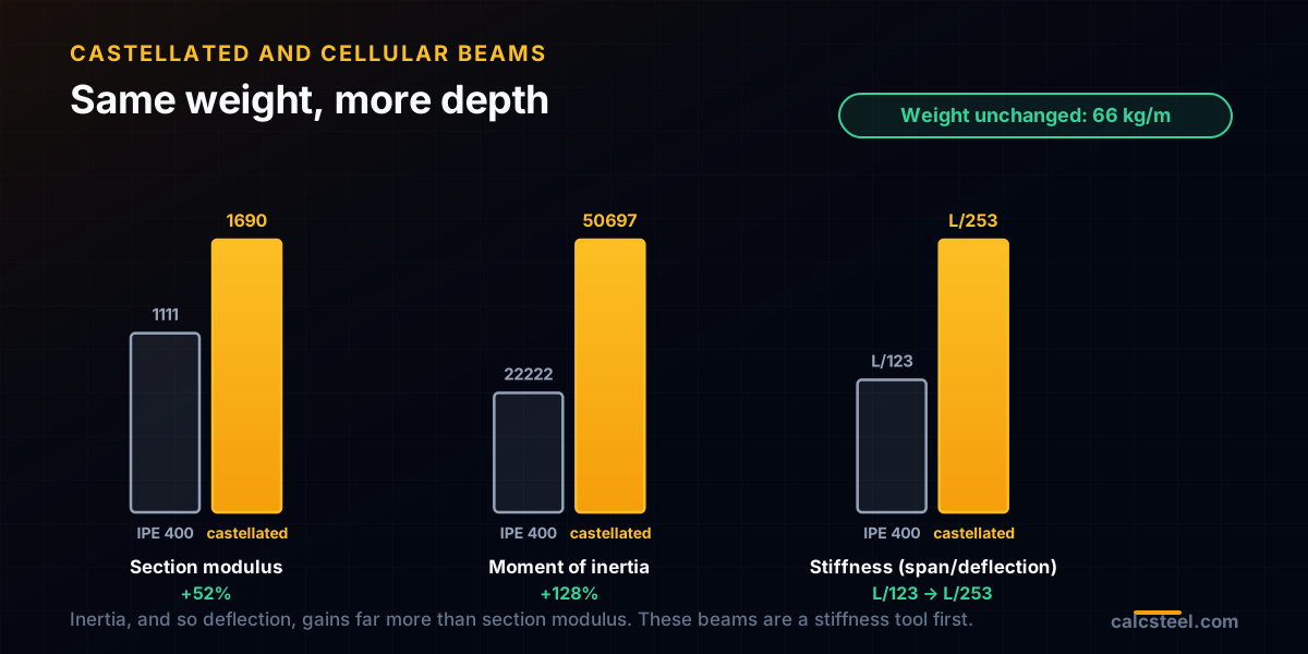
- Expanding a rolled section for depth is nearly free of weight: our IPE 400 castellated to 600 mm gains 128 percent moment of inertia and 52 percent section modulus at the same 66 kg/m.
- Depth buys stiffness fastest: the 12 m beam moves from L/123 (a fail) to L/253 at no added weight, because deflection scales with the cube of depth.
- The openings add limit states a solid web never has: Vierendeel bending of the tees, web post horizontal shear, and web post buckling.
- Vierendeel is the signature check. On our beam the gross section reads 48 percent, but the governing opening reads 0.55 once the tee axial force and the local Vierendeel moment are added.
- Castellated and cellular beams shine on long, lightly loaded, deflection governed spans, and are poor where shear governs: short spans and heavy loads near supports.
- Every number here is engine-computed or checked against AISC Design Guide 31 Example 001, whose net inertia we reproduce to 196.9 of the published 197.6 in^4.
More depth, same steel: the trade at the heart of it
Open any beam table and the pattern is blunt: to carry more, or to sag less, you buy depth. The moment of inertia grows with the square of depth and the section modulus with depth itself, while deflection falls with the cube of it. Weight, by comparison, buys you very little. A castellated beam takes that fact literally.
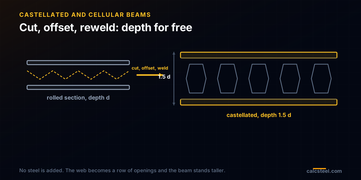
You start with an ordinary rolled I section. A machine flame cuts its web along a repeating zigzag line, splitting the beam into two toothed halves. Slide one half along by one tooth, lift the peaks of one onto the peaks of the other, and weld the contact points. The web is now a row of hexagonal holes, and the finished beam stands taller than the one you started with. No steel was added. A cellular beam is the same idea with a circular cutting line instead of a zigzag, leaving round holes.
The number that matters: our IPE 400 parent has a moment of inertia of 22 222 cm4. Castellated to 600 mm it reaches 50 697 cm4 at the net section, an increase of 128 percent, and its section modulus climbs 52 percent, from 1 111 to 1690 cm3. The mass per metre barely moves, staying near 66 kg/m. That is the whole attraction, and the rest of this guide is the price you pay for it.
Castellated or cellular: hexagons versus circles
Both members are expanded rolled sections, and the difference is only the shape of the cut. Castellated beams use a single zigzag cut, so the offset halves leave hexagonal openings and a straight welded joint at mid height. This is the classic Anglo-Saxon and Peiner pattern: a cutting angle near 60 degrees, a finished depth about 1.5 times the parent depth, and an opening height roughly equal to the parent depth.
Cellular beams use two arc cuts, and the thin crescents between them are discarded, leaving circular holes. Because a circle wastes those slivers, a cellular beam loses a little steel that a castellated beam keeps, but the round hole is cleaner for services and spreads stress better around its edge. Manufacturers set the opening diameter near 0.6 to 0.8 of the finished depth and space the holes about 1.5 diameters apart.
The engine puts numbers on the choice. Keeping the same 600 mm finished depth, our cellular version with a 450 mm opening reaches a net section modulus of 1625 cm3, a 46 percent gain over the parent, a touch below the castellated 52 percent, because the larger round hole removes more of the web at the critical section. Both are strong; the pick usually comes down to the services you need to thread through the web and the look you want.
Why depth wins, and where the win is largest
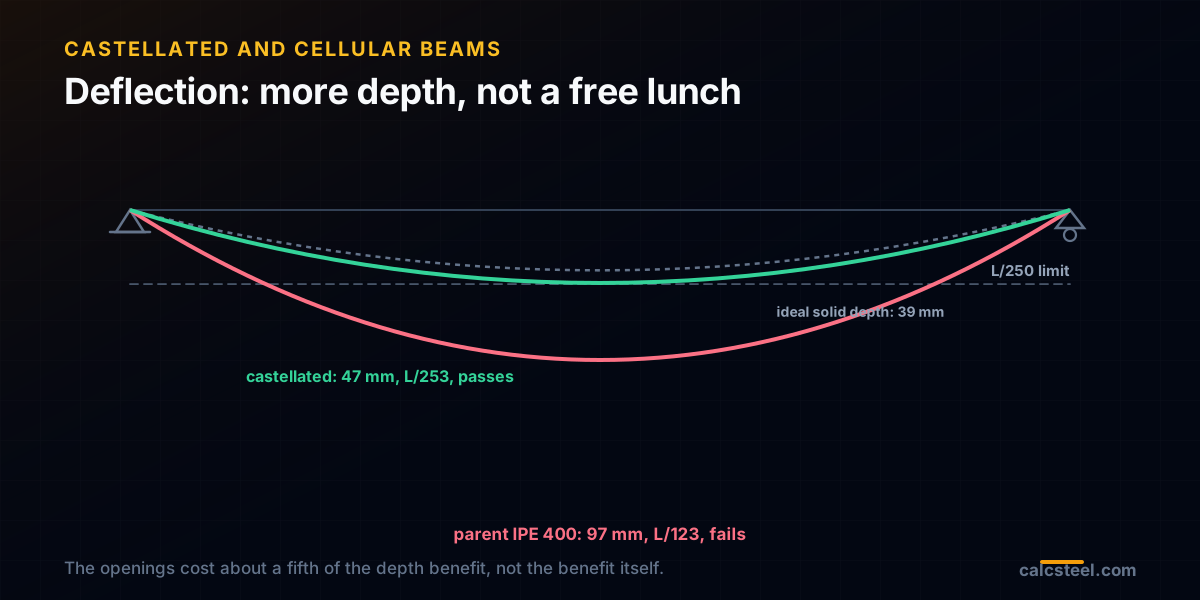
Run the parent IPE 400 first, on a 12 m simply supported span under a 16 kN/m service load. The engine returns a maximum moment of 288 kN m and a maximum shear of 96 kN, a bending stress of 259 MPa, and a utilisation of 73 percent against S355. On strength alone it survives. On deflection it does not: it drops 97 mm, or L/123, well past the L/250 a roof or floor beam is usually held to. This is the classic long span problem, where deflection, not stress, is the wall you hit.
Castellate the same section to 600 mm and rerun it. Bending stress falls to 170 MPa and utilisation to 48 percent, because the deeper section carries the same moment on a larger lever arm. Deflection is the bigger prize: it drops to 47 mm, or L/253, which clears the limit. The parent failed serviceability; the castellated beam passes it, at the same 66 kg/m.
Notice the asymmetry. Section modulus rose 52 percent but moment of inertia rose 128 percent, because inertia rewards depth harder. That is why these beams are a deflection tool first and a strength tool second. When a member is governed by how far it moves rather than how hard it is stressed, added depth at constant weight is close to the perfect medicine.
The geometry: naming the parts of a cut web
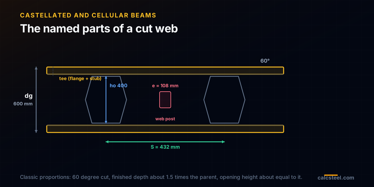
To check a castellated beam you first have to name it. The parent depth is d. The finished depth after expansion is dg, here 600 mm, about 1.5 d. Each opening has a height ho, here 400 mm, close to the parent depth. Above and below every opening sits a tee: a flange plus a short stub of web, with a depth of tt = (dg minus ho) / 2, here 100 mm. The two tees are what actually carry the beam past each hole.
Along the length, the openings repeat at a pitch S, here 432 mm, so a 12 m beam holds about 26 of them. Between two openings the web is solid over a short length called the web post, whose narrow welded throat has a length e of about 108 mm. That throat is the most stressed strip of steel in the whole member, and two of the added checks live there.
These proportions are not arbitrary. The classic patterns fix the cutting angle near 60 degrees so the tees are deep enough to carry local bending and the web post is wide enough not to buckle. Push the expansion much past 1.5, or the openings much wider, and the checks below start to bite before the flanges ever do.
Two sections in one beam: net at the hole, gross at the post
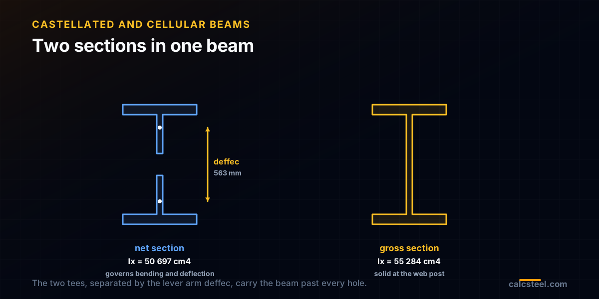
A solid beam has one cross section. A castellated beam has two, and they alternate every few hundred millimetres. At the centre of an opening the section is just the two tees separated by a hole: this is the net section, and it is what governs bending strength and stiffness. At the web post the section is solid to the full finished depth: this is the gross section, and it matters for the web post checks.
The net moment of inertia is easy to get honestly. Take the solid section at the finished depth, which the engine computes as 55 284 cm4, and subtract the web rectangle the hole removes. That leaves 50 697 cm4, which is also exactly what you get by summing the two tees about the beam axis with the parallel axis theorem: the two methods agree, and both match AISC Design Guide 31 Example 001 to within a fraction of a percent. The distance between the two tee centroids, deffec, is 56 cm, and it is the internal lever arm the whole member works on.
Each tee is small: an area of just 32 cm2 and an elastic modulus of only 24 cm3 about its own axis. Hold on to that second number. A tee is a poor beam in its own right, and the next check asks it to be exactly that.
Vierendeel bending: the check the openings add
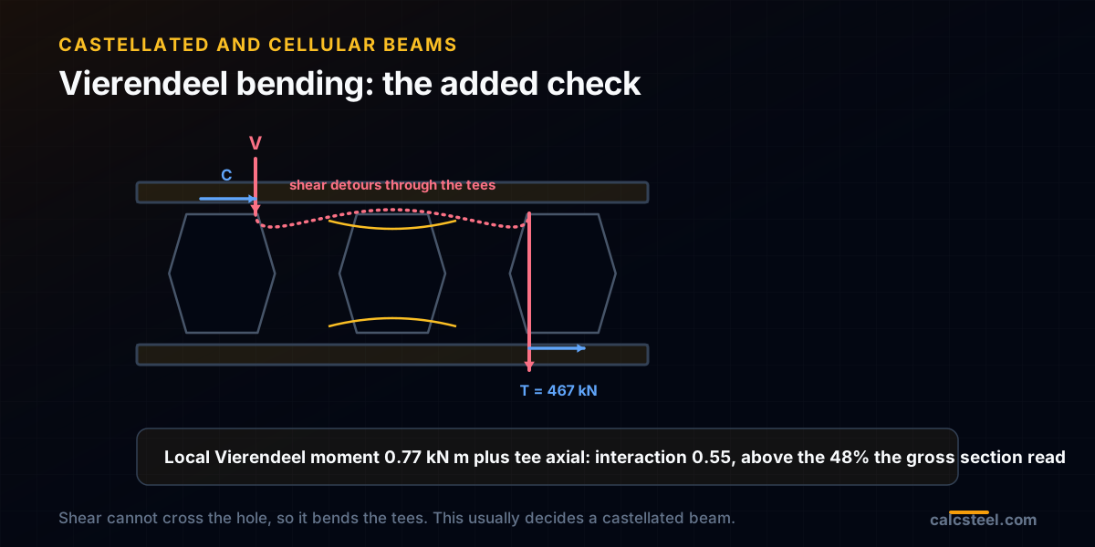
Here is what a hole does to shear. In a solid web, vertical shear flows straight down through the web. At an opening there is no web to flow through, so the shear has to detour around the hole, up into the top tee, across, and down the far side. Carrying shear across a gap means bending, and so the tees bend locally over each opening. This is Vierendeel action, named after the open web truss with no diagonals, and it is the check that defines these beams.
Two forces land on each tee at once. The global moment pulls the tees apart as an axial couple: the tension in the bottom tee is T = M / deffec. The global shear bends each tee locally over half the opening, a Vierendeel moment of roughly V/2 times the arm, here about 54 mm. You then check the tee for combined axial force and bending, the same AISC Chapter H interaction a beam column uses.
Watch where it governs. On our beam the gross bending utilisation is a comfortable 48 percent. But at the opening 7.8 m from the support, the tee tension reaches 467 kN against a capacity near 1014 kN, and the local Vierendeel moment of 0.77 kN m eats into the tee's tiny bending capacity of about 7.5 kN m. Add them through the interaction and the opening reads 0.55, higher than the 48 percent the gross section suggested. The hole, not the flange, is the real limit, and it does not sit at midspan or at the support but where high moment and rising shear overlap.
The web post: horizontal shear and buckling
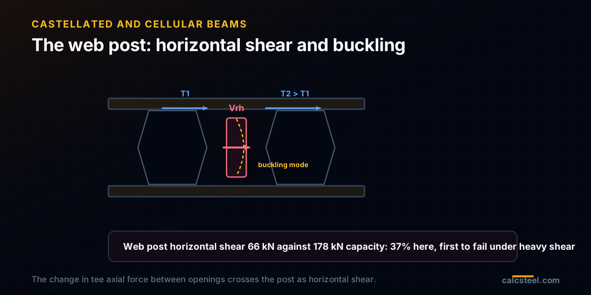
The web post is the sliver of solid web between two openings, and it earns two checks of its own. The first is horizontal shear. The tee axial force is larger under the opening nearer midspan than under the one nearer the support, and that difference has to be passed from one to the other through the post. It arrives as a horizontal shear across the welded throat.
On our beam the horizontal shear in the worst web post is 66 kN, against a throat shear yield capacity of about 178 kN, so it runs at 37 percent: comfortable here, because the beam is long and lightly loaded. Shorten the span or add a heavy point load and this is one of the first things to fail, which is exactly why these beams dislike heavy shear.
The second check is web post buckling. That same horizontal shear bends the post out of plane, and being short and thin it can buckle like a little column. Design Guide 31 handles it with empirical curves fitted to finite element studies, reading a critical to plastic moment ratio from the post slenderness. It rarely governs on a well proportioned beam, but it is why you cannot simply make the openings as wide, or the posts as thin, as you please. Where shear is high, the fix is to fill an opening solid or to move it, restoring a length of ordinary web just where the beam needs it most.
Deflection: more depth, but not a free lunch
Depth helps deflection more than anything, but the holes give some of it back. A castellated beam bends about its reduced net inertia, not the solid inertia its outline suggests, and on top of that the tees shear and distort locally at every opening, adding a shear deflection a solid beam does not have. Design Guide 31 bundles both effects into an effective inertia of about 0.9 of the net value, which is the figure we used.
The bookkeeping is worth seeing. An ideal solid beam of the finished 600 mm depth would deflect only 39 mm. The real castellated beam, with its net inertia and the 0.9 factor, deflects 47 mm, about a fifth more. Even so, that is L/253, comfortably better than the parent's L/123. The openings cost you a slice of the depth benefit, not the benefit itself.
The practical rule follows from this. Because a castellated beam gives up ground on shear and gains it on stiffness, it belongs on spans where serviceability is the fight. Size it for deflection, then confirm the openings on shear, rather than the other way round.
When to reach for one, and when not to
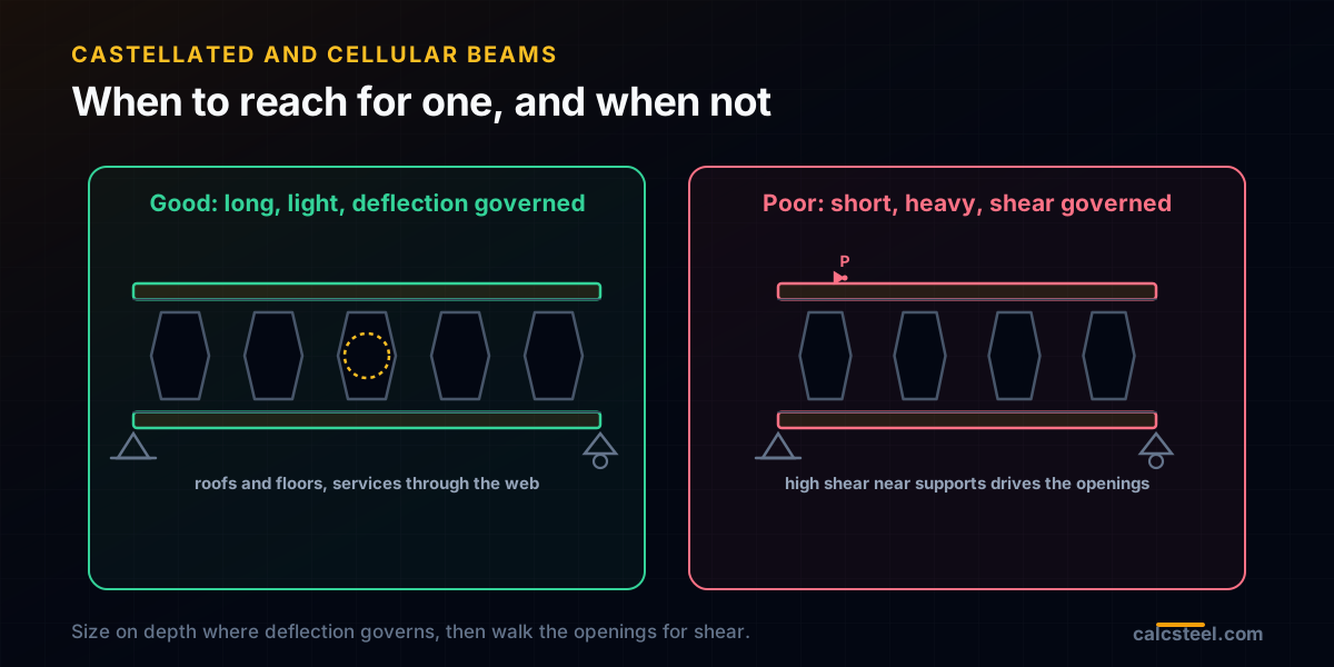
Everything above points the same way. Castellated and cellular beams are long span, lightly loaded, deflection governed members. Roof beams, floor beams over wide column grids, transfer members in commercial buildings: places where the beam is fighting its own flexibility and where the openings double as a duct and service route through the web, saving floor to floor height. On those jobs the depth for free is close to unbeatable.
They are a poor choice where shear governs. Short heavy spans, beams with large point loads, and the support regions of any beam are exactly where the Vierendeel and web post checks bite hardest, because that is where shear peaks. A crane girder or a stocky transfer beam is the wrong home for a row of holes. When a mostly good candidate has a bad patch, a high shear zone near a support, the standard move is to fill or omit the openings there and keep them where the beam is bending, not shearing.
One habit protects you. Do not read the gross section and stop. A castellated beam that looks half worked in bending can be fully worked at an opening, and the two numbers live in different places. Size on depth, then walk the openings.
How we know the numbers: validating against Design Guide 31
None of this is worth publishing unless the method is right, so we did not trust our own arithmetic. Before touching the metric beam, we reproduced the worked example inside AISC Design Guide 31 itself: a W12x14 root castellated to 17.8 in. Our net moment of inertia comes out at 196.9 in4 against the guide's published 197.6, the distance between tee centroids and the tee area match to the third digit, the governing tee tension lands on the guide's 46.6 kips, and the web post horizontal shear matches too.
Only then did we run the metric IPE 400 on the shipping CalcSteel solver for the moment, shear and deflection, and apply the same, now trusted, opening checks by hand. The gross section properties at the finished depth come straight from the engine and agree with our own section arithmetic to the whole number. The rule we follow on every one of these posts is simple: a formula only ships once it has reproduced a published example, and a load effect only ships once the engine has computed it.
Try it: size a beam and watch depth do the work
The fastest way to feel why depth beats weight is to move it yourself. Set a span and a load below, then step the section deeper and watch the moment utilisation and the deflection fall together, faster than the weight rises. That is the exact lever a castellated beam pulls, before you add the opening checks on top.
Once a beam is in the deflection governed regime, where added depth is worth far more than added weight, an expanded section becomes the obvious answer. Then, and only then, you walk the openings for Vierendeel bending and the web post, the way this guide did.
Max moment
45 kN·m
Max shear
30 kN
Max deflection
10.55 mm
= L/569
Bending stress σ
84.4 MPa
σ = M/Sx
Utilization
44.0%
NBR 8800 · δ ≤ L/250
Geometry & supports
Section
Ix 7999 cm⁴ · Sx 533 cm³ · 42.2 kg/m
Point loads (↓ positive)
None — add as many as you need.
Distributed loads (uniform or trapezoidal)
Model sketch
Diagrams — free PNG / SVG / CSV export, no watermark
Step-by-step — the calculation memory of YOUR beam
IPE 300 · L = 6 m · fy = 250 MPa
1. Reactions (equilibrium of the solved FEM model)
ΣFy = 0 · ΣM = 0
R_A = 30 kN · R_B = 30 kN
2. Peak shear (read from the SFD)
Vmax = |V(x)|max
Vmax = -30 kN @ x = 6 m
3. Peak moment (read from the BMD)
Mmax = |M(x)|max
Mmax = 45 kN·m @ x = 3 m
4. Peak deflection
EI = 15998 kN·m² (E = 200 GPa)
δmax = 10.55 mm @ x = 3 m = L/569
5. Elastic bending stress
σ = Mmax / Sx = 45.00 × 10³ / 533.3
σ = 84.4 MPa
6. Bending check — both codes, side by side
NBR 8800: σ ≤ fy/1.10 = 227.3 MPa · AISC 360: σ ≤ 0.90·fy = 225 MPa
NBR 37.1% PASS · AISC 37.5% PASS
7. Deflection check (serviceability — code-independent)
δ ≤ L/250 = 24 mm
10.55 mm / 24 mm = 44.0% PASS
Recomputed live from the current inputs by the direct-stiffness FEM engine — change any load and every step updates. Reproduce it by hand with the formulas in the sections below.
Lightest catalog profiles that pass (974 flexural candidates · NBR 8800)
| Profile | Std | Weight | Total steel | σ util | δ util | |
|---|---|---|---|---|---|---|
| W310x21 | AISC | 21 kg/m | 126 kg | 83% | 98% | |
| VS 300x23 | BR | 22.6 kg/m | 136 kg | 71% | 84% | |
| U 300x90x6.3 | BR | 23.1 kg/m | 139 kg | 82% | 98% | |
| U 300x100x6.3 | BR | 24.1 kg/m | 145 kg | 77% | 91% | |
| VS 250x25 | BR | 24.6 kg/m | 148 kg | 70% | 100% |
Elastic bending (σ = M/Sx vs fy/γa1, γa1 = 1.10 — NBR 8800) + deflection screening of the full flexural catalog. Lateral-torsional buckling, shear and local buckling are NOT checked here — run the full NBR 8800 / AISC 360 verification in the 3D editor.
Sources
Try CalcSteel for free
Model, analyze and design steel structures in your browser. No install, no signup.
Open the 3D editor