3D Steel Design Software: What the Third Dimension Changes, and the Member That Fails Only in It
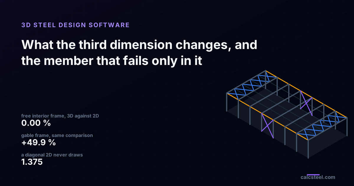
3D steel design software is a software phrase for a modelling question, so this article answers it by measurement. One 20 m by 42 m warehouse is run twice on the same shipping CalcSteel engine: once as the eight separate 2D portals a hand workflow produces, and once as one 3D model with the purlins, the eaves struts, the roof wind girder and the wall bracing actually drawn. The answer is uncomfortable in both directions. On the frame you already know how to draw, the two models agree to 0.00 %, so the third dimension buys you nothing. On half the frames of the same building they do not agree at all, by +49.9 % and by 24.9 %. And the one member that fails its code check, at a ratio of 1.375, is a member the 2D workflow never draws.
Key takeaways
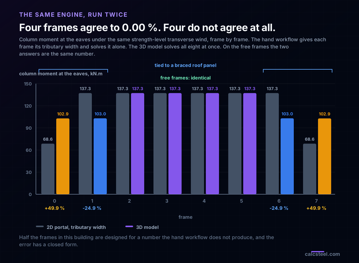
- On a free interior frame the two models give the same number. Column moment at the eaves 137.28 kN.m both ways, exactly V H / 2, and sway 42.149 mm against 42.193 mm, a difference of 0.105 %. For that frame the 2D portal is not an approximation of the 3D answer, it is the 3D answer
- Four of the eight frames are not that frame. A braced roof panel makes each gable sway with its neighbour, so the pair splits the sum of its tributary shears: (17.16 + 34.32) / 2 = 25.74 kN, giving 102.96 kN.m against the 68.64 kN.m a tributary hand calc assigns the gable, which is +49.9 %
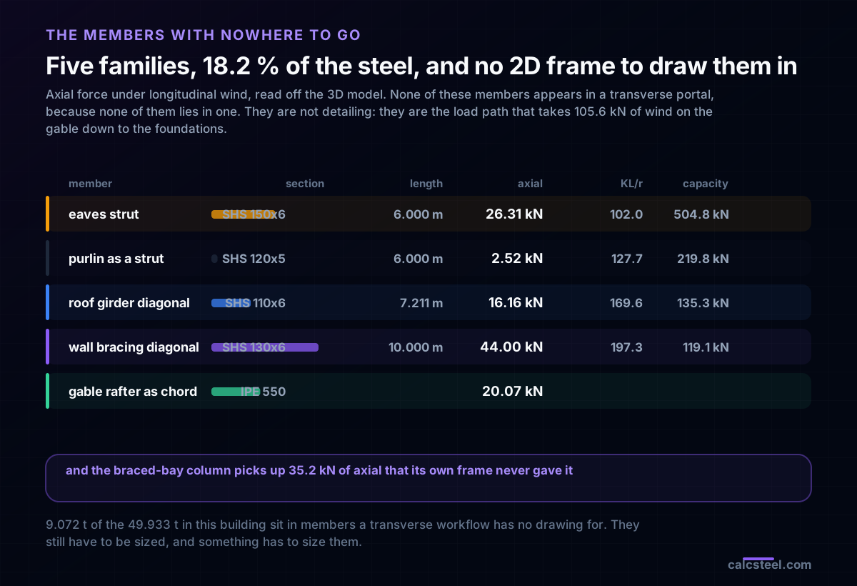
- Five member families carry real force in the 3D model and have no place in a transverse portal at all: eaves strut 26.31 kN, purlin 2.52 kN, roof girder diagonal 16.16 kN, wall diagonal 44.00 kN and the gable rafter working as a chord at 20.07 kN. They are 9 072 kg, which is 18.2 % of this building
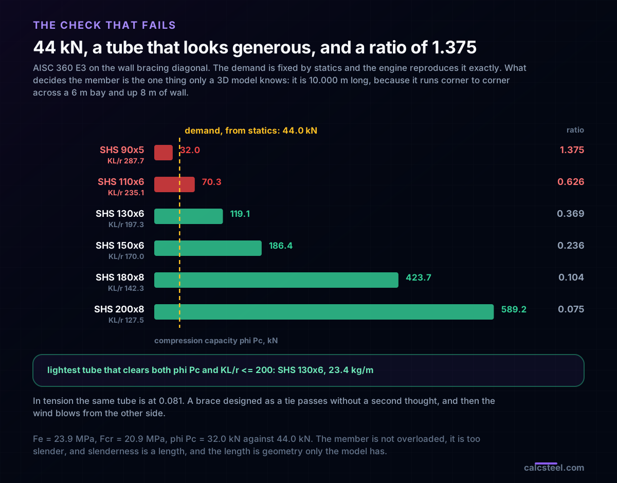
- The worked check fails on the wall bracing diagonal. The demand is only 44.0 kN, but the member is 10.000 m long, so SHS 90x5 gives KL/r = 287.7, Fcr = 20.9 MPa and phi Pc = 32.0 kN, a ratio of 1.375. The same tube in tension is at 0.081, which is how the mistake survives review
- The criterion never moved. AISC 360 H1-1 runs 0.0041 to 0.0923 on every column in both models, and what sizes this building is the H/250 drift limit at 29.504 mm against 32.0 mm. The third dimension changed the list of members the criterion is applied to, not the criterion
The question hiding inside the phrase
Nobody actually wants three dimensions. What people want when they search for 3D steel design software is an answer to a question they cannot resolve from a feature list: is the frame I already know how to draw by hand going to come out different, and if it does, by how much and which way?
That is a measurable question, so this article measures it instead of arguing about it. One building, modelled twice, solved by the same engine, with every result checked against a closed form you can reproduce on paper. Not a 3D tool against a 2D tool, which would only compare two vendors: the same solver, given the same steel, arranged the two ways the profession actually arranges it.
The result has three parts, and only the middle one is the part that sells software. The third dimension does not change the criterion. On a typical interior frame it does not change the numbers either. It changes which members exist, and on this building that is where the only failing check lives.
One building, two models
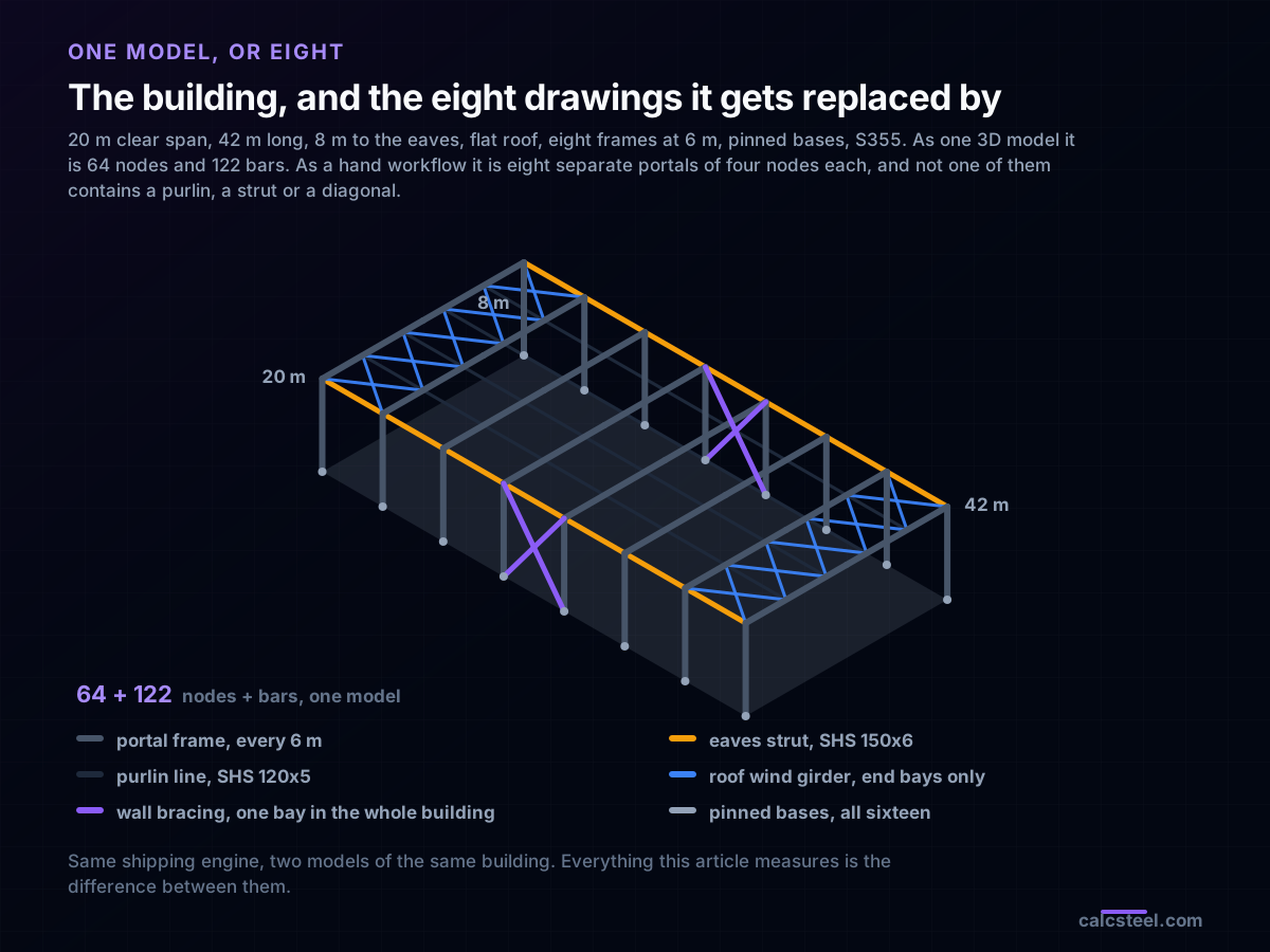
A single-storey portal warehouse: 20 m clear span, 42 m long, 8 m to the eaves, eight frames at 6 m, pinned bases, S355. The roof is flat, deliberately, so that every hand check in this article stays exact and you can follow the algebra without a pitch correction. Columns are HEB 500, rafters IPE 550, and the bracing is the arrangement a real building gets: a roof wind girder in the two end bays, and wall bracing in exactly one bay out of seven.
The hand workflow turns that into eight separate portals, each four nodes, each given its tributary width of wind and solved alone. The gables get half a bay, the interior frames a full bay. Nothing else is modelled, because a transverse portal has nowhere to put a purlin.
The 3D workflow turns the same building into 64 nodes and 122 bars: the eight frames, six purlin lines across the span, eaves struts down both sides, the roof wind girder in the end bays and the X bracing in the one braced wall bay. Wind is 240.2 kN total on the long face, and 105.6 kN on the gable.
Where the two models agree, they agree exactly
Start with the result that argues against buying anything. Take a free interior frame, one not touching a braced roof panel, and compare the two models under the same strength-level transverse wind.
| frame 3, transverse wind | 2D portal | 3D model | closed form |
|---|---|---|---|
| column moment at the eaves | 137.28 kN.m | 137.28 kN.m | V H / 2 = 137.28 |
| eaves sway | 42.193 mm | 42.169 mm | 42.175 mm |
| difference | 0.00 % on moment, 0.056 % on sway | slope deflection | |
The column moment is not close, it is identical, and it is identical to the value you get on the back of an envelope: a pinned-base portal splits the storey shear between two columns, the pin at the foot carries no moment at all, and the whole of it lands at the top of the column: V H / 2 = 34.32 x 8 / 2 = 137.28 kN.m. The sway agrees with the slope-deflection expression to four figures.
Say that plainly, because software marketing rarely does. For a free interior frame, the 2D portal is not an approximation of the 3D answer. It is the 3D answer. If your building is one frame, or all your frames are free, the third dimension will return your own arithmetic to you, and it will be right to do so.
Half the frames are not the frame you checked
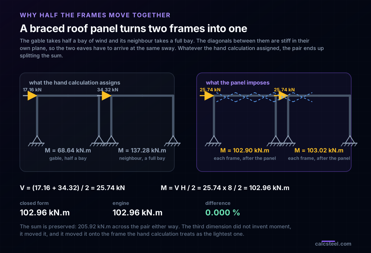
Now look at the ends of the same chart. The gable frame takes +49.9 % more column moment than its tributary hand calculation gives it, 68.64 kN.m becoming 102.90 kN.m, and its immediate neighbour sheds 24.9 %, 137.28 kN.m falling to 103.02 kN.m.
This is not a solver artefact and it is not mesh noise. It is the roof wind girder doing exactly what it was put there to do. The diagonals in the end bay are stiff in their own plane, so the two eaves they connect cannot sway by different amounts. Once two frames must sway together, the load they were separately assigned stops mattering and only the total does. The pair splits the sum:
V = (17.16 + 34.32) / 2 = 25.74 kN per frame, so M = V H / 2 = 25.74 x 8 / 2 = 102.96 kN.m.
The engine returns 102.90 and 103.02 kN.m, a mean of 102.96 and a difference from the closed form of 0.000 %. Nothing was invented: the sum across the pair is 205.92 kN.m in both models. The moment moved, and it moved onto the frame the hand workflow treats as the lightest one in the building.
The serviceability side moves with it. At the 0.70 wind factor the gable sways 22.128 mm instead of the 14.761 mm the hand calculation predicts, which is H/362 rather than H/542. Both still pass here. On a taller building, or one with a tighter limit, the frame that fails first would be the one the spreadsheet says has the most margin.
Run the 2D half yourself
Before going further, it is worth having the 2D number in your own hands, because the whole argument rests on the two models being given the same steel. The portal frame calculator below runs the same solver on a single frame. Enter a 20 m span, 8 m height, pinned bases and 34.32 kN of horizontal load, and the moment comes back as 137.3 kN.m whatever section you pick, because that number is statics. The sway is not: it follows the stiffness, and the calculator gives the rafter the same section as the column, so an HEB 500 reads 31.7 mm where the frame in this article, which carries a lighter rafter, reads 42.2 mm.
That is the honest baseline. Everything a 3D model adds has to be measured against this, not against a straw man.
Diagrams plotted on the deformed-free frame geometry. N, V, M recovered from the element end-forces of the direct-stiffness solve (12 elements / member). Moment drawn offset to each member's centreline.
First-order STRENGTH screening at the governing section of the NBR 8800 (BR) ULS envelope (governing CB2): N,d = 73.9 kN, M,d = 109 kN·m. Member buckling and lateral-torsional buckling are NOT included — see the stability flags below and run the full verification in the 3D editor. Click a card to make that resistance code govern the ranking.
ULS load combinations — NBR 8800 (BR)
G + W superposed · 3 combinations| Combination | Factors | Utilization |
|---|---|---|
| CB1 | 1.4 G | 69% |
| CB2governs | 1.4 G + 1.4 W | 76% |
| CB3 | 1 G + 1.4 W | 57% |
Combinations generated by the CalcSteel combinations engine (the same v4 engine the 3D editor uses, 6 codes). Gravity is treated as a single permanent action G; the wind action W is the eaves load. Each combination's γ factors are applied by superposition to the isolated gravity and wind solves, then every section is screened — the worst point of the worst combination governs.
Stability screening (buckling caveats)
not in the strength checkScreening indicators only — assumed sway effective length (K = 1.5) and the full member length as the unbraced length (no intermediate purlin/girt restraint). The strength check above deliberately excludes these; the real member verification (effective lengths from the alignment chart / notional loads, χ and Cb reduction factors, purlin bracing) runs in the 3D editor.
Lightest sections that pass (NBR)
screened 974 profiles| Profile | Mass | Frame steel | Utilization | |
|---|---|---|---|---|
| VS 400x32 | 31.9 kg/m | 723 kg | 82% | |
| VS 350x33 | 33.2 kg/m | 752 kg | 86% | |
| VS 400x34 | 34.4 kg/m | 779 kg | 75% | |
| VS 350x35 | 35.1 kg/m | 795 kg | 80% | |
| VS 400x35 | 35.1 kg/m | 795 kg | 73% |
The members that have nowhere to live
The redistribution above is interesting. This next part is the one that actually costs money.
Under longitudinal wind, 105.6 kN arrives on the gable and has to reach the foundations. It travels along the purlins into the roof wind girder, along the eaves struts to the braced bay, down the wall diagonals and into the ground. Every member on that path carries real force, and not one of them lies in a transverse portal, so a 2D transverse workflow has no drawing in which to put it.
| member | section | length | axial | KL/r | phi Pc |
|---|---|---|---|---|---|
| eaves strut | SHS 150x6 | 6.000 m | 26.31 kN | 102.0 | 504.8 kN |
| purlin as a strut | SHS 120x5 | 6.000 m | 2.52 kN | 127.7 | 219.8 kN |
| roof girder diagonal | SHS 110x6 | 7.211 m | 16.16 kN | 169.6 | 135.3 kN |
| wall bracing diagonal | SHS 130x6 | 10.000 m | 44.00 kN | 197.3 | 119.1 kN |
| gable rafter as a chord | IPE 550 | 4.000 m | 20.07 kN |
Each of those is statics, and the engine reproduces statics. One side wall takes half the gable load, and the braced bay has two active diagonals, so each carries (105.6 / 2 / 2) / 0.6 = 44.0 kN. The engine returns 44.00 kN, a difference of 0.00 %. The eaves strut ferries 26.40 kN to that bay and the engine returns 26.31 kN, 0.33 % low, because a little of it leaks through the frames. The vertical component of the diagonal, 44.0 x 0.8 = 35.2 kN, lands as extra axial force in the braced-bay column, and the engine returns 35.2 kN. That column is carrying an axial load its own transverse frame never gave it.
Weigh the two lists and the members outside the transverse frames come to 9 072 kg of 49 933 kg, or 18.2 % of the steel. That fraction has to be sized by something. In a 2D workflow it is sized by a separate longitudinal model, by a standard detail, or by judgement, and the risk is not that judgement is wrong, it is that nothing in the transverse run will ever contradict it.
The worked check, and it fails
Take the wall bracing diagonal and run it properly, AISC 360 Chapter E, phi = 0.90, S355.
The demand is 44.0 kN. That is a small number. A designer sizing this member from the force alone would reach for a modest tube and move on, and an SHS 90x5 has a factored tensile capacity of 543.1 kN, which makes 44 kN look like nothing at all.
What the 3D model contributes is not the force. It is the geometry: the member runs from a base corner to the eaves node one bay away, across 6 m and up 8 m, so it is 10.000 m long. Put that length into E3 and the picture inverts:
- r = 34.8 mm, so KL/r = 287.7, well past the 200 that AISC E2 advises as a practical ceiling
- elastic buckling stress Fe = 23.9 MPa, against Fy = 355 MPa
- critical stress Fcr = 20.9 MPa, which is 5.9 % of the yield stress
- phi Pc = 32.0 kN against a demand of 44.0 kN, a ratio of 1.375
The member is not overloaded. It is too slender, and slenderness is a length, and the length is a piece of geometry that only exists once the building is drawn in three dimensions.
Two things make this the check worth publishing. The first is the trap: the same tube in tension is at 0.081. Size the brace as a tie, which is entirely conventional, and it passes with a factor of twelve to spare. The failure only appears when the wind comes from the other side and the software is asked the compression question.
The second is that the answer depends on a modelling decision you have to make on purpose. This model has both diagonals of the X active in tension and compression, which is what you get when you draw two tubes and say nothing else. Design them tension-only instead and one diagonal takes the whole 52.8 kN of wall shear as 88 kN of tension, the compression member is ignored, and SHS 90x5 survives. That is a legitimate design, widely used, and it is a choice. The point of the 3D run is not that the tube is wrong. It is that in the 2D transverse workflow the member is never drawn, so the choice is never presented.
Walking up the catalogue with both diagonals active, the lightest tube that clears both phi Pc and the KL/r ceiling is SHS 130x6 at 23.4 kg/m, ratio 0.369: 75.9 % heavier than the tube the force alone suggested.
Delete the roof bracing and watch the 2D model not notice
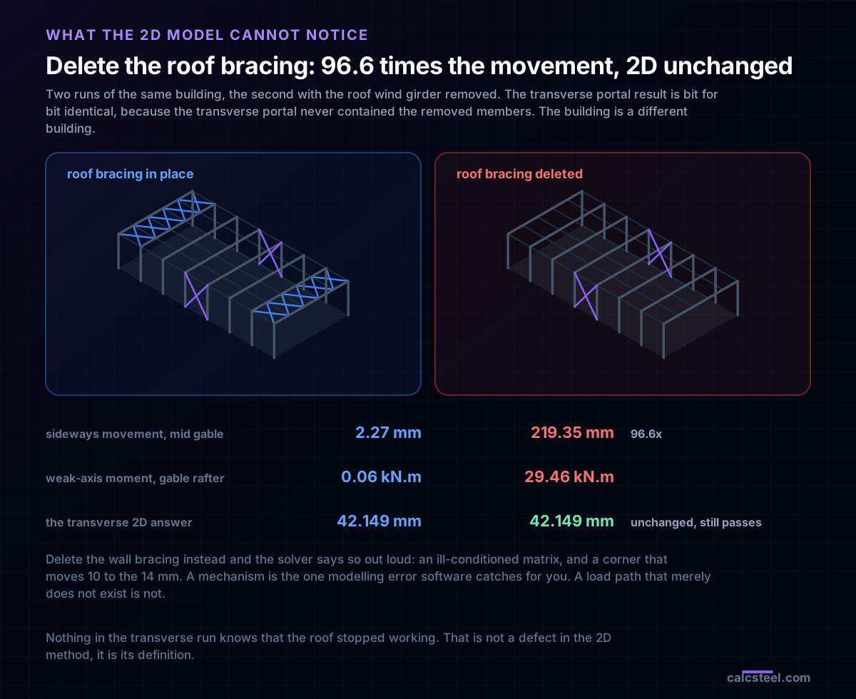
The clearest demonstration of what a model contains is to break it. Remove the roof wind girder from the 3D model, change nothing else, and run both models again.
| with roof bracing | roof bracing deleted | |
|---|---|---|
| sideways movement, mid gable | 2.27 mm | 219.35 mm |
| weak-axis moment, gable rafter | 0.06 kN.m | 29.46 kN.m |
| the transverse 2D answer | 42.149 mm | 42.149 mm |
The building moves 96.6 times further, and an IPE 550 that was never intended to bend about its weak axis picks up 29.46 kN.m of it, because with the girder gone the only route left for the gable reaction is weak-axis bending of the gable rafter. Meanwhile the transverse portal returns 42.149 mm, unchanged to the last digit, and still passes its drift check.
That is not a defect in the 2D method. It is the definition of it. A model reports on the members it contains, and a transverse portal has never contained a roof diagonal, so there is no result in it that could possibly change.
It is worth knowing where software does protect you. Delete the wall bracing instead and the building becomes a mechanism in the longitudinal direction: the solver emits an ill-conditioned matrix warning and returns a corner displacement of the order of 10 to the 14 mm, which nobody will mistake for a result. A mechanism is caught. A load path that is merely terrible, 219 mm of movement, is not caught by anything except you reading the number.
There is no diaphragm unless you draw one
A common defence of the tributary method is that the roof will spread things out anyway. It is worth testing, because it is easy to test: put the entire 240.2 kN of transverse wind on a single interior frame and see what the neighbours do.
The loaded frame sways 292.87 mm. Its two immediate neighbours sway 0.625 mm and 1.232 mm, which is 0.21 % and 0.42 %. Every other frame is under 0.62 mm, and the far half of the building sits at zero to three decimal places.
So the purlins, struts and roof diagonals that were drawn faithfully in this model still do not act as a diaphragm. They tie the braced panels together, which is what produced the +49.9 % earlier, and outside those panels they transmit almost nothing sideways. A rigid roof diaphragm is a modelling assumption you impose on purpose, with a deck stiffness you can defend. It is not something a 3D model gives you for free, and it is not something the tributary method can quietly rely on.
The criterion behind the code did not move
With all of that measured, run the actual code checks on the columns, in both models, and the anticlimax is the finding.
| combination | P | M | H1-1 ratio |
|---|---|---|---|
| 1.2D + 1.6Lr, interior column | 49.20 kN | 0.00 kN.m | 0.0041 |
| 1.2D + 1.0W + 0.5Lr, interior frame | 39.36 kN | 137.28 kN.m | 0.0923 |
| same, gable frame, the 2D answer | 19.68 kN | 68.64 kN.m | 0.0462 |
| same, gable frame, the 3D answer | 19.68 kN | 102.90 kN.m | 0.0684 |
| 0.75 transverse plus 0.75 longitudinal, braced bay | 65.76 kN | 102.96 kN.m | 0.0722 |
The gable column does rise 48.1 % when you move from the 2D answer to the 3D answer, and it rises from 0.046 to 0.068. Both pass by a mile. Nothing about interaction, about phi, about Fcr or about the H1-1 equation itself changed between the two models, because none of that is a property of the model.
What sizes this building is serviceability. The free frame sways 29.504 mm under the 0.70 wind factor against an H/250 limit of 32.0 mm, which is H/271 and leaves 7.8 % of margin. The HEB 500 columns are there for that 29.5 mm, not for the 0.0923. Stability is comfortable too: lateral stiffness 814.3 kN/m gives an elastic critical ratio of 66.2 and B2 = 1.0153, so first-order analysis is allowed and second-order effects are worth 1.5 %.
That is the honest summary of what the third dimension did. It did not touch the criterion. It changed the demand side on four of eight frames, and it added sixty-six members, of the 122 in the model, to the list the criterion has to be applied to.
When the 2D workflow is the right tool
Everything above is an argument for 3D only if you ignore the first result. A 2D portal workflow is exactly right when the conditions that made frame 3 agree hold:
- The frame is free. No braced roof panel connects it to a neighbour with a different tributary width. In this building that is four frames out of eight, and in a longer building it is most of them
- The load really is tributary. Uniform bay spacing, uniform wind, no openings, no crane corbel on one frame and not the next
- The out-of-plane members are sized elsewhere, by someone, on paper. A separate longitudinal model or a standard bracing detail is a perfectly good answer, as long as it exists
- You are early. For sizing a column in a tender, V H / 2 on the back of an envelope is within 0.00 % of what the 3D model will eventually tell you, and it takes thirty seconds
The cases where it stops being the right tool are the mirror image, and they are specific rather than vague: gable frames next to a braced bay, any bay where bracing lands, buildings where the bracing pattern is not symmetric, longitudinal load paths in general, and any member whose unbraced length you would otherwise have to guess. That last one is where the 1.375 came from.
What to actually check when you evaluate 3D software
If the measurements above are what the third dimension buys, then the feature list worth reading is short, and it is not the one on most product pages.
- Does it give you the member length it used? The whole worked check turned on 10.000 m. A tool that computes buckling without showing you the unbraced length it assumed has hidden the governing variable
- Does it check compression in braces, or only tension? And does it let you declare a brace tension-only, explicitly, rather than guessing what you meant
- Does it report per-frame results, not just envelopes? The +49.9 % and the 24.9 % cancel inside a whole-model envelope. You have to be able to see frame 0 next to frame 3
- Does it tell you what governed? On this building the answer is a drift limit, and a tool that only prints strength ratios would have you reading 0.0923 and believing the building had a factor of ten in hand
- Does it warn when a load path is missing? Be realistic here: no tool does. It will warn about a mechanism, because the mathematics forces it to. The 219 mm case is on you
Notice that none of those is about rendering. Three dimensions are worth paying for as an accounting of members and load paths, not as a picture. The picture is how you audit the accounting.
What the third dimension is actually for
Three numbers carry the whole article. On a free interior frame the two models differ by 0.00 %. On the gable frames they differ by +49.9 %. And one member, invisible to the transverse workflow entirely, comes back at 1.375 against AISC 360 E3.
Put together, they say something more useful than 3D being better. The criterion behind the code is indifferent to how you modelled the building: H1-1 is H1-1, phi is 0.90, and a drift limit is a drift limit. What the model decides is the inventory. Which members exist, how long they are, what is tied to what, and therefore which checks ever get run at all.
The eight portals in this building were not wrong. Four of them were exactly right, to the digit. They were incomplete, by four frames and by 18.2 % of the steel, and being incomplete is the failure mode that no amount of care inside the 2D run will surface. That, and not the rendering, is the thing the third dimension is for.
Sources
- 1.AISC 360, Specification for Structural Steel Buildings, Chapter E (E2 slenderness, E3 flexural buckling), Chapter F and Section H1-1
- 2.ASCE/SEI 7, Minimum Design Loads and Associated Criteria for Buildings and Other Structures, load combinations and Appendix CC serviceability wind
- 3.AISC Design Guide 3, Serviceability Design Considerations for Steel Buildings, drift limits for low-rise frames
- 4.AISC Steel Design Guide 7, Industrial Buildings: Roofs to Column Anchorage, bracing and longitudinal load paths
- 5.EN 1993-1-1, Eurocode 3: Design of steel structures, general rules, alpha cr and the limit for first-order analysis
- 6.CalcSteel portal frame calculator, the single-frame solver used for the 2D half of this comparison
Try CalcSteel for free
Model, analyze and design steel structures in your browser. No install, no signup.
Open the 3D editor