Wind Load Calculation: From ASCE 7 to a Steel Frame
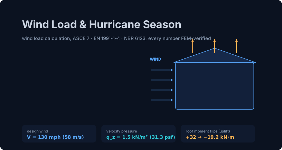
Wind load calculation from ASCE 7 to a hurricane-tested steel portal frame, with FEM-verified numbers and a free load-combination calculator, no login.
Key takeaways
- Velocity pressure q_z = 0.00256·Kz·Kzt·Kd·Ke·V² gives 31.26 psf (1.497 kN/m²) at 130 mph, becoming 1.287 kN/m² of windward pressure and 1.414 kN/m² of roof uplift.
- In the portal frame, wind barely moved the rafter peak (257.7 to 254.2 kN·m) but multiplied sidesway drift about 330 times (0.003 to 1.08 cm, H/555).
- Under 0.9D + 1.0W the roof beam moment flipped from +32.0 kN·m sagging to −19.2 kN·m hogging, reversing the reactions to −9.6 kN of net uplift into the connections.
- The girt's 1.287 kN/m² pressure over a 1.5 m spacing gave 1.931 kN/m and M_max = 8.69 kN·m, matched by the FEM engine to three decimals.
- Design reduces to one number: utilization = demand / capacity < 1.0, checked automatically against AISC 360, Eurocode 3 or NBR 8800.
Wind Load Calculation: From ASCE 7 to a Steel Frame
It is hurricane season, and somewhere on the coast a single-storey steel warehouse is about to meet a design wind speed of 130 mph (58.1 m/s). That number is not weather trivia: it is the input that decides how thick the columns are, how the roof stays attached, and whether the anchor rods hold when the storm tries to lift the whole building off its foundation. Getting the wind load calculation right is the difference between a building that shrugs off a hurricane and one that ends up as debris.
This guide walks the entire path, end to end: from a raw ASCE 7 velocity pressure in psf, through factored load combinations, and into a real steel portal frame analysed with a finite-element engine. Every result you will see is engine-verified, not hand-waved: we ran three worked examples through the CalcSteel FEM solver and print the exact numbers it returned. Along the way there is a live load-combination calculator you can drive yourself, for free, with no login.
We wrote this for three readers at once:
- The student who needs the physics and the formula to actually make sense (start at how wind loads a building).
- The practising engineer who wants the code bookkeeping, the governing combinations and the frame behaviour (jump to the portal-frame example).
- The curious reader who just wants to know why roofs peel off in a hurricane (that answer lives in worked example 3, and it hinges on a moment that literally changes sign).
Keep that last point in the back of your mind as you read. Wind rarely governs a beam by making its bending moment bigger. It governs by flipping the load upward, unbalancing a frame sideways, and putting connections that were designed to push into pure tension. That reversal is the whole story, and only a real structural model captures it cleanly.
How wind actually loads a building
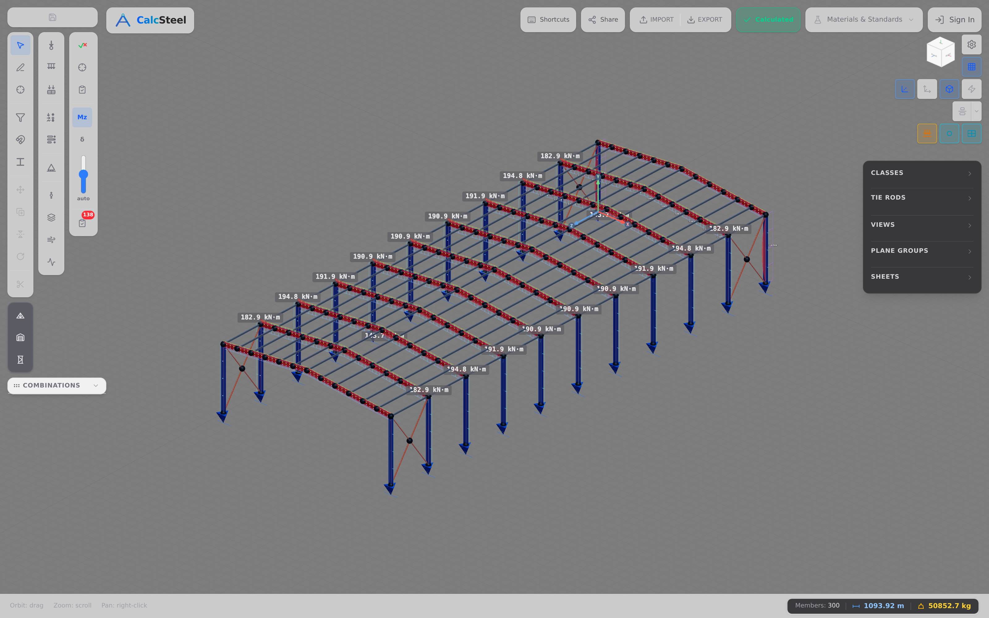
Wind load is the pressure a moving mass of air exerts on a structure: it pushes inward on the windward face, pulls outward (suction) on the leeward and side walls, and lifts upward on the roof. It is a surface pressure, measured in kN/m² (or psf), that acts perpendicular to every face the wind touches, and it changes direction depending on which side of the building you stand.
The physics starts with dynamic pressure. When moving air is brought to rest against a wall, its kinetic energy converts to pressure, and the stagnation (dynamic) pressure of an air stream is:
q = ½ ρ V²
where ρ is the air density and V is the wind speed. Two things jump out. First, pressure grows with the square of the speed, so a wind that is 40% faster does not hit 40% harder, it hits roughly twice as hard. That is why a jump from an everyday gust to a 130 mph (58.1 m/s) hurricane wind is so violent. Second, this is just the raw physics; every design code then wraps q in correction factors for height, terrain, gustiness and shape.
Wind does not simply press on everything, though. Depending on the surface, you get either pressure (pushing in) or suction (pulling out):
- Windward wall (facing the wind): positive pressure, pushing into the building.
- Leeward wall (downwind) and side walls: negative pressure, suction pulling the wall outward as the air separates and flows past.
- Roof: on a low-slope roof the air speeds up as it shears over the ridge, and by Bernoulli's principle that faster flow drops the pressure above the roof. The result is uplift, a net suction pulling the roof up and off the frame.
That roof uplift is the counter-intuitive part and the dangerous one. Gravity loads always push a roof down into its supports; wind can reverse that and try to pull it up. When the upward wind suction beats the downward weight, the roof-to-frame connections stop being in compression and go into tension. Hold that thought: it is exactly the mechanism we quantify in worked example 3, and it is why hurricanes win against buildings that were only ever checked for gravity.
Calculating wind load: velocity pressure (ASCE 7)
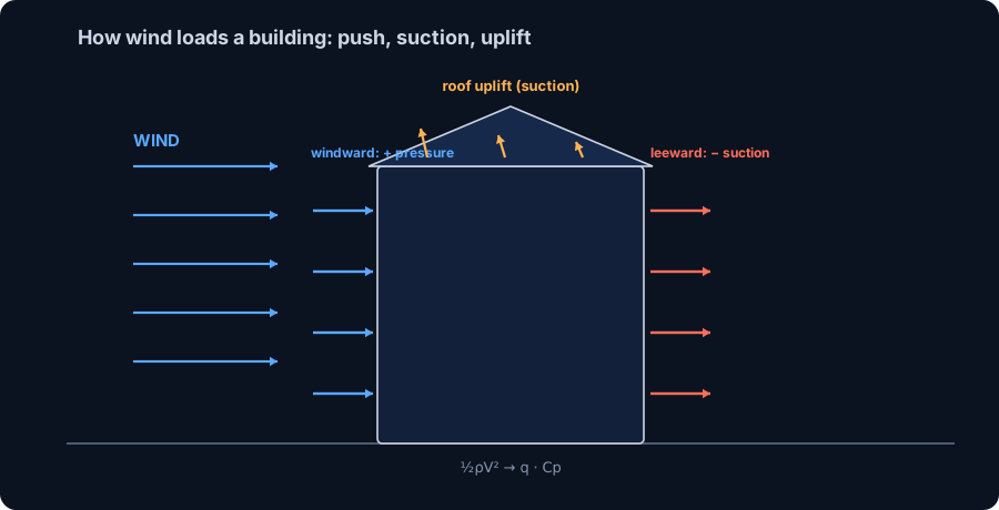
ASCE 7-22, the US standard, turns the raw dynamic pressure into a design velocity pressure qz with a single working formula (in US customary units, with V in mph and the result in psf):
qz = 0.00256 · Kz · Kzt · Kd · Ke · V²
The constant 0.00256 is just the ½ρ of standard air rolled up with the unit conversion. Everything else is a factor that adjusts the raw pressure for the real site:
- Kz (velocity pressure exposure coefficient): accounts for height above ground and terrain roughness. Wind speeds up the higher and the more open the site. For Exposure C (open terrain, typical for a coastal warehouse) at our mean roof height, Kz = 0.85.
- Kzt (topographic factor): amplifies wind over hills, ridges and escarpments where the flow accelerates. On flat ground Kzt = 1.0.
- Kd (wind directionality factor): a small reduction (0.85 for buildings) that accounts for the low probability that the very worst wind direction lines up with the very worst structural response at the same moment.
- Ke (ground elevation factor): corrects air density for elevation above sea level. At sea level Ke = 1.0.
Plugging in Kz=0.85, Kzt=1.0, Kd=0.85, Ke=1.0 and V=130 mph:
qz = 31.26 psf = 1.497 kN/m².
That is the velocity pressure, but it is not yet the pressure on a wall. To get the design pressure on a surface you scale q by the shape and gust behaviour of that surface:
p = q · (G · Cp − GCpi)
Here G = 0.85 is the gust-effect factor, Cp is the external pressure coefficient (the surface shape factor), and GCpi = ±0.18 is the internal pressure coefficient for an enclosed building (the pressure inside the box that either helps or fights the external pressure, so it always carries a ± sign). Working the two critical surfaces:
- Windward wall (external Cp = +0.8): the net design pressure works out to about 26.88 psf = 1.287 kN/m², pushing inward. This is the load we drive into the wall girt in worked example 1.
- Leeward wall (Cp = −0.5): suction pulling outward.
- Low-slope roof, windward (Cp ≈ −0.9): net uplift ≈ −29.54 psf = 1.414 kN/m², a suction pulling the roof straight up. Note it is larger than the inward wall pressure, which is exactly why uplift, not push, is the load that governs a roof.
Every one of these numbers is a hand calculation you can reproduce with a pencil. The moment they enter a real frame, though, the arithmetic stops being linear, and that is where the FEM engine earns its keep. First, let us see the codes that get you to this same pressure by different routes.
Three codes, one idea: ASCE 7 vs Eurocode vs NBR 6123
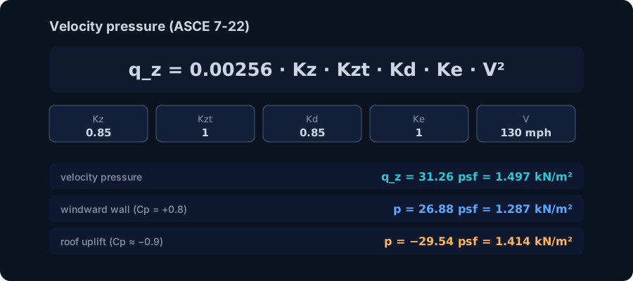
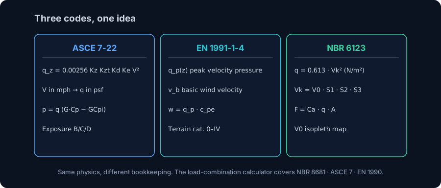
Wind physics is universal, but every region books it differently. If you work across markets, or you learned one code and are reading a project in another, it helps to see that ASCE 7, Eurocode and NBR 6123 are the same ½ρV² idea wearing three different sets of clothes. All three start from a basic wind speed, correct it for terrain, height and topography, square it to get a pressure, then apply shape coefficients. Only the names and the packaging change.
- ASCE 7-22 (United States): works in mph and psf. You start from the basic wind speed V (a mapped 3-second gust tied to a risk category), form the velocity pressure qz with the K-factors, and apply G·Cp and internal GCpi. This is the route we worked above.
- EN 1991-1-4 (Eurocode, Europe): starts from a basic wind velocity vb, applies terrain-category and orography factors to build a peak velocity pressure qp, then multiplies by external and internal pressure coefficients cpe and cpi plus a structural factor cscd. Different symbols, identical logic: speed to pressure to surface load.
- NBR 6123 (Brazil): starts from the basic wind speed V0 (a 50-year, 3-second gust from the isopleth map), adjusts it with three factors S1 (topography), S2 (roughness, height and building dimension) and S3 (statistical/importance) to get the characteristic velocity Vk, then computes the characteristic dynamic pressure q = 0.613 · Vk² (in N/m² with Vk in m/s). That 0.613 is nothing more than ½ρ for standard air in SI units, the exact same constant hiding inside ASCE 7's 0.00256.
The takeaway is liberating: if you understand one code deeply, you understand all three, because the engineering is one equation and the codes are bookkeeping conventions around it. What differs in practice is the shape coefficients, the terrain categories and, crucially, the load combinations each code pairs with its wind pressure.
That last point is where mistakes creep in when you cross borders, so we handle it for you. The CalcSteel load-combination calculator generates the factored combinations for NBR 8681, ASCE 7 and EN 1990 side by side, with the wind factors broken out explicitly, so you can see how the same characteristic wind load is amplified differently under each standard. It is free and needs no login, and it is embedded a little further down this page for you to try.
Worked example 1: a wall girt under wind
Theory is cheap until it has to hold a wall together in a storm. So let us take the pressure we just calculated and put it on a real member: a wall girt, the horizontal beam that spans between columns and carries the cladding. This is the cleanest place to start because a girt is statically determinate: simply supported at each end, one span, one load. The hand formula and the FEM engine should agree to the last decimal, and they do.
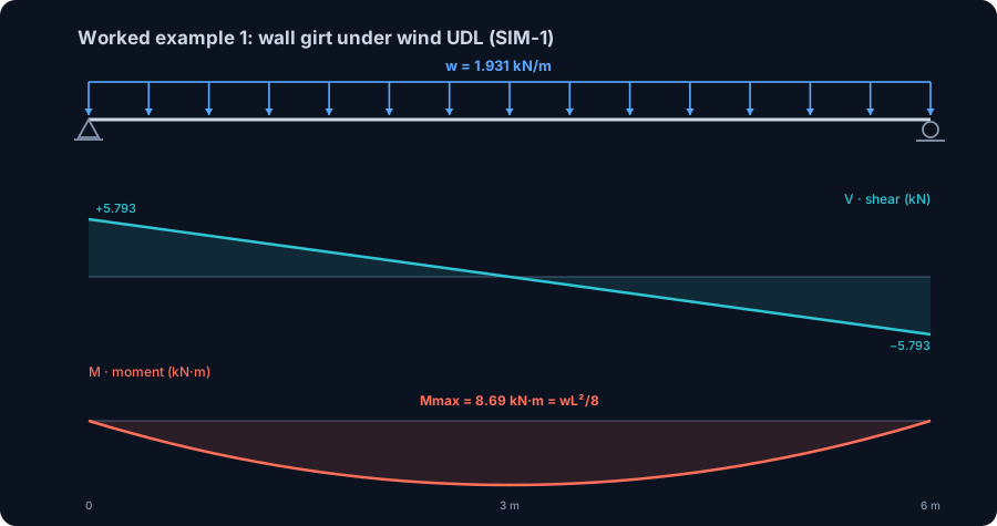
Here is the setup. The windward wall sees the design pressure from the velocity pressure section: 1.287 kN/m² pushing inward (that is the 26.88 psf net windward-wall value). Each girt supports a strip of wall one girt-spacing wide. With a girt spacing of 1.5 m, the area pressure collapses into a line load along the girt:
- w = 1.287 kN/m² × 1.5 m = 1.931 kN/m (a uniformly distributed load, acting perpendicular to the wall).
The girt spans L = 6 m between columns, pinned at both ends. From here the classic simply supported results apply:
- End reactions: R = wL / 2 = 1.931 × 6 / 2 = 5.793 kN at each support.
- Maximum shear: Vmax = 5.793 kN, occurring at the supports (shear is largest where the reactions are, and it crosses zero at midspan).
- Maximum moment: Mmax = wL² / 8 = 1.931 × 6² / 8 = 8.69 kN·m, at midspan.
We ran the identical girt through the CalcSteel FEM engine, and it returned R = 5.793 kN, Vmax = 5.793 kN, and Mmax = 8.69 kN·m, an exact match to three decimals. That is the whole point of a determinate check: when closed-form theory and the solver agree perfectly, you trust the solver on the hard problems where no closed form exists (that is Example 2). If you want to see how those shear and moment values are built up along the span, the walkthrough in shear force and bending moment diagrams takes the same simply supported case apart step by step.
One warning that matters in a hurricane: this 8.69 kN·m assumes the girt is on the windward face, where the pressure pushes inward and bends the girt one way. On the leeward and side walls the pressure reverses into suction (Cp = −0.5 on the leeward wall), so the same girt bends the other way and its outer flange, not its inner flange, goes into compression. A girt is symmetric enough that the magnitude is what governs the section, but the sign reversal is exactly the kind of thing that decides which flange needs bracing. You size the girt for the worst case in either direction, then hand it to the beam calculator to confirm the section and the deflection.
Try it: live load-combination calculator
Before we load a whole frame, get your hands on the numbers yourself. The calculator embedded right here builds the factored load combinations for you: it takes your dead, live, wind and other actions and generates the full ULS (strength) and SLS (service) combination sets side by side for NBR 8681, ASCE 7 and EN 1990, with the wind factors broken out so you can see exactly where the 1.0W, the 0.9D and the load factors land.
That side-by-side view is the fastest way to internalise the single most important idea in this article: wind does not act alone, and the combination that governs is often not the obvious one. Type in a dead load and a wind load, then watch how 0.9D + 1.0W (dead-load help minimised, wind maximised) produces a completely different, and frequently more dangerous, demand than 1.2D + 1.0W. That is the case that lifts roofs, and we prove it with the FEM engine two sections down.
- Free, no login, nothing to install. It runs in your browser like the rest of the CalcSteel calculators.
- It speaks three codebooks at once, so a student learning ASCE 7 and a practising engineer working to NBR 8681 or Eurocode see the same physics in their own notation.
Open the load-combination calculator, run your own D, L and W, then come back: the next two worked examples take these exact combinations and push them through a real steel frame.
NBR 8681
82.6 kN
governing ULS
ASCE 7-16/22
71 kN
governing ULS
EN 1990
84 kN
governing ULS
Code spread
18.3%
EN 1990 governs
Governing ULS by code — parcel makeup
NBR 8681
Ultimate (ULS / ELU)
Serviceability (SLS / ELS)
ASCE 7-16/22
Ultimate (ULS / ELU)
Serviceability (SLS / ELS)
EN 1990
Ultimate (ULS / ELU)
Serviceability (SLS / ELS)
24 combinations across 3 codes · math in SI, display in kN
Load combinations: where wind gets dangerous
Wind never shows up by itself. A real building is always carrying its own weight, its roof and floor loads, sometimes snow, and the wind arrives on top of all of that (or, in the dangerous case, works against it). Load combinations are the rulebook that says how much of each action to apply at once, and for wind they are where the design is won or lost.
The reason you need several wind combinations, not one, is that dead load can be either your friend or your enemy depending on which way the wind acts:
- 1.2D + 1.0W + 1.0L (with live load): wind pushes with gravity on the walls and columns. Here dead and wind stack up, and this case tends to govern the columns, which now carry axial force plus the bending that wind adds. That interaction is its own topic, covered in combined axial and bending.
- 0.9D + 1.0W (the uplift / overturning case): this is the one people forget, and it is the one that peels roofs off. You deliberately minimise the dead-load help (only 0.9 of it) and apply full wind uplift. When wind suction on the roof exceeds the reduced gravity holding it down, the net load reverses upward: moments flip sign and connections go into tension. We prove exactly this with the FEM engine in Example 3.
Every major code encodes the same physics with different bookkeeping, and the embedded load-combination calculator lays them out together:
- ASCE 7 (US): the LRFD strength combinations, including 1.2D + 1.0W + L + 0.5(Lr or S) and the critical 0.9D + 1.0W for uplift and overturning.
- Eurocode (EN 1990): the ULS expressions 6.10a and 6.10b, with wind as either the leading or an accompanying variable action (its ψ combination factors), and the favourable/unfavourable partial factors on permanent load that play the same role as ASCE's 1.2 versus 0.9.
- NBR 8681 (Brazil): the normal, special and exceptional combinations with γ factors on permanent load and ψ0 reduction factors on the non-leading variable actions, wind included.
The takeaway before we run the numbers: you must check the frame under the combination that helps gravity and the combination that fights it. For members, 1.2D + 1.0W usually wins. For the roof, the connections and the anchors, 0.9D + 1.0W is the killer, and the next roof-beam example shows why in hard numbers.

Worked example 2: the frame sways (portal frame + wind)
The girt in the previous example was determinate: one span, two supports, a formula. A real building is not. Take a single-storey portal-frame warehouse: a 20 m span, 6 m eave columns, fixed bases, a 6 m bay, W610x125 rafters and columns. Push wind against one side and the whole frame leans. There is no closed-form answer for the moments, because the structure is statically indeterminate: the loads redistribute according to relative stiffness, and only a finite-element solve tells you where they land. This is exactly the case where hand methods stop and a real FEM engine earns its keep.
We ran two load cases on the same frame in the CalcSteel engine.
Case A, gravity only. A uniform rafter load of wg = 6 kN/m down. Because the frame is symmetric, the answer is symmetric too:
- Rafter peak moment: 257.7 kN·m at midspan.
- Knee (eave) moment: 42.3 kN·m.
- Column base moment: -21.1 kN·m.
- Eave sidesway drift: ~0.003 cm, essentially zero. A symmetric frame under symmetric load does not lean.
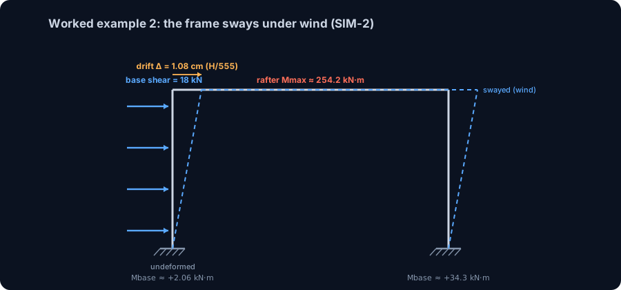
Case B, gravity plus wind. Keep the 6 kN/m gravity and add lateral wind as a UDL of 3 kN/m on the windward column, which is 18 kN of total base shear. Now watch what moves and what does not:
- Rafter peak moment: 254.2 kN·m. The wind barely touched it (257.7 to 254.2).
- Knee moment: 37.0 kN·m (down from 42.3).
- Windward-column base moment: +2.06 kN·m; leeward-column base moment: +34.3 kN·m. The wind unbalances the two feet left-to-right, and both flip sign relative to the gravity case.
- Eave sidesway drift: 1.08 cm. The frame now leans.
The base reactions confirm the physics closes: ΣFx = -18 kN, the fixed feet resist the 18 kN wind push exactly, and ΣFy = 120 kN (= 6 kN/m × 20 m of gravity). Nothing leaks.
Here is the insight that hand calc will never hand you. Wind moved the peak beam moment by barely 1% (257.7 to 254.2 kN·m), but it multiplied the sidesway drift by roughly 330 times (0.003 to 1.08 cm) and it flipped and unbalanced the base and knee moments side-to-side. In other words, wind does not govern the beam, it governs the columns and the drift check. The columns now carry axial load and a lateral bending they did not see under gravity, which is the classic combined action covered in combined axial and bending. If you had modelled this frame as pinned, or checked only gravity, you would have missed the entire story.
Is 1.08 cm acceptable? The drift ratio is H/Δ = 600/1.08 ≈ 555, comfortably inside a typical wind drift limit of H/400 to H/500. That is a serviceability check, not a strength one, and it is precisely the kind of limit we unpack in deflection limits. A frame can pass every stress check and still be rejected on drift, so both matter.
You can build this exact frame in the CalcSteel editor, apply the gravity and wind cases, and read the moment diagram and the drift straight off the model. The lateral stiffness that keeps that 1.08 cm small comes from the fixed bases here, but in taller or wider frames it comes from bracing: see bracing systems for steel and columns, beams and bracing for how the lateral load path is actually resolved.
Worked example 3: uplift flips the roof (why hurricanes win)
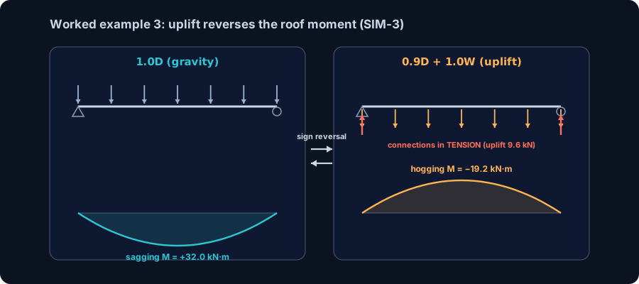
This is the one that peels roofs off. Back on determinate ground, take a simply supported roof beam spanning 8 m. It carries a downward dead-plus-roof load of wD = 4 kN/m, and in a hurricane it sees a wind uplift of wW = 6 kN/m acting up. Notice that the uplift is larger than the dead load. That single fact is the whole hurricane story.
Gravity case, 1.0D. Net load is +4 kN/m downward. The beam sags:
- Midspan moment: +32.0 kN·m, sagging, so the bottom flange is in tension (= wL²/8).
- Reactions: +16 kN at each end. The beam pushes down into its supports, which is what supports are used to.
Uplift combination, 0.9D + 1.0W. This combination deliberately minimises the dead-load help (factor 0.9) and maximises the wind (factor 1.0), because that is when uplift is worst. The net load becomes:
0.9 × 4 - 6 = -2.4 kN/m, acting upward.
- Midspan moment: -19.2 kN·m. It is now hogging: the moment sign has flipped (= wnet·L²/8).
- Reactions: -9.6 kN at each end. The sign flipped here too: each support is now being pulled up by 9.6 kN of net uplift.
Read what physically changed. The moment went from +32.0 to -19.2 kN·m. The bottom flange, which was in tension under gravity, is now in compression, so a member that was fine may buckle where it was never braced for it. And the reactions reversed: the roof-to-frame connections that spent their whole life being pushed down are now in net tension, 9.6 kN of pull per support. If those connections were detailed only to sit and bear (a clip, a couple of stitch screws, a base plate with no holddown), the wind simply lifts the roof off. That is not a metaphor. That is the exact mechanism.
This is why the 0.9D + 1.0W combination exists and why you cannot skip it: gravity-only design never reveals the tension case, so the connection that fails in a hurricane is invisible until you run the reversal. The moment reversal is easiest to see on a sign-changing diagram, the same tool we build up in shear force and bending moment diagrams. You can reproduce both cases in seconds on the free beam calculator, or generate the pair of factored combinations automatically with the load combination calculator and watch the net load go negative.
The lesson for detailing is blunt: size the member for the sag, but design the connection for the uplift. Holddowns, anchor rods and uplift-rated clips are not optional on a hurricane coast, they are the load path, which is exactly where the next section goes.
The hurricane load path: connections, not members
Example 3 ended with a number that should worry you more than any bending stress: 9.6 kN of net tension at every roof-to-frame connection. Hurricanes rarely snap a rafter in half. They find the weakest link in the load path and undo it, and that link is almost always a connection or an anchor, not a member.
Trace the uplift from the sky to the ground and you get the continuous load path that has to survive intact:
- Cladding to purlin/girt. The suction on the roof and walls first tries to tear the sheeting off its fasteners. Screw pattern and edge distance decide this.
- Purlin/rafter to frame. The 9.6 kN pull travels into the clips and bolts connecting secondary members to the main frame. Under gravity these were in bearing; under 0.9D + 1.0W they are in tension.
- Rafter to column (the knee). In the portal of Example 2 the knee moment shifted from 42.3 to 37.0 kN·m and the whole frame leaned 1.08 cm. The moment connection at the knee has to carry that, and it also carries the lateral shear into the columns.
- Column to foundation. This is where net uplift becomes anchor-rod tension and base-plate bending. The base plate that only needed to spread a compression under gravity now has to be checked for uplift and prying, and the anchor rods have to develop their tension into the concrete.
A load path is only as strong as its weakest connection. You can design every W610x125 to a utilization of 0.6 and still lose the building if the anchor rods were sized for compression only. The chain governs, not the members.
Two more base checks that wind forces on you, both of them global rather than local:
- Overturning. The 18 kN base shear from Example 2 and the roof uplift together try to tip the frame about its leeward feet. The dead load resists it, which is exactly why the 0.9D factor (minimum dead) is the overturning-critical combination.
- Sliding. That same 18 kN of horizontal push has to be transferred into the foundation without the base plates walking sideways, through anchor shear and friction.
The columns themselves are now the classic beam-column: axial from gravity plus bending from wind, checked together, never separately. That interaction is the subject of combined axial and bending, and the lateral stability that keeps the whole thing from racking is the job of the bracing scheme in bracing systems for steel and the member roles in columns, beams and bracing.
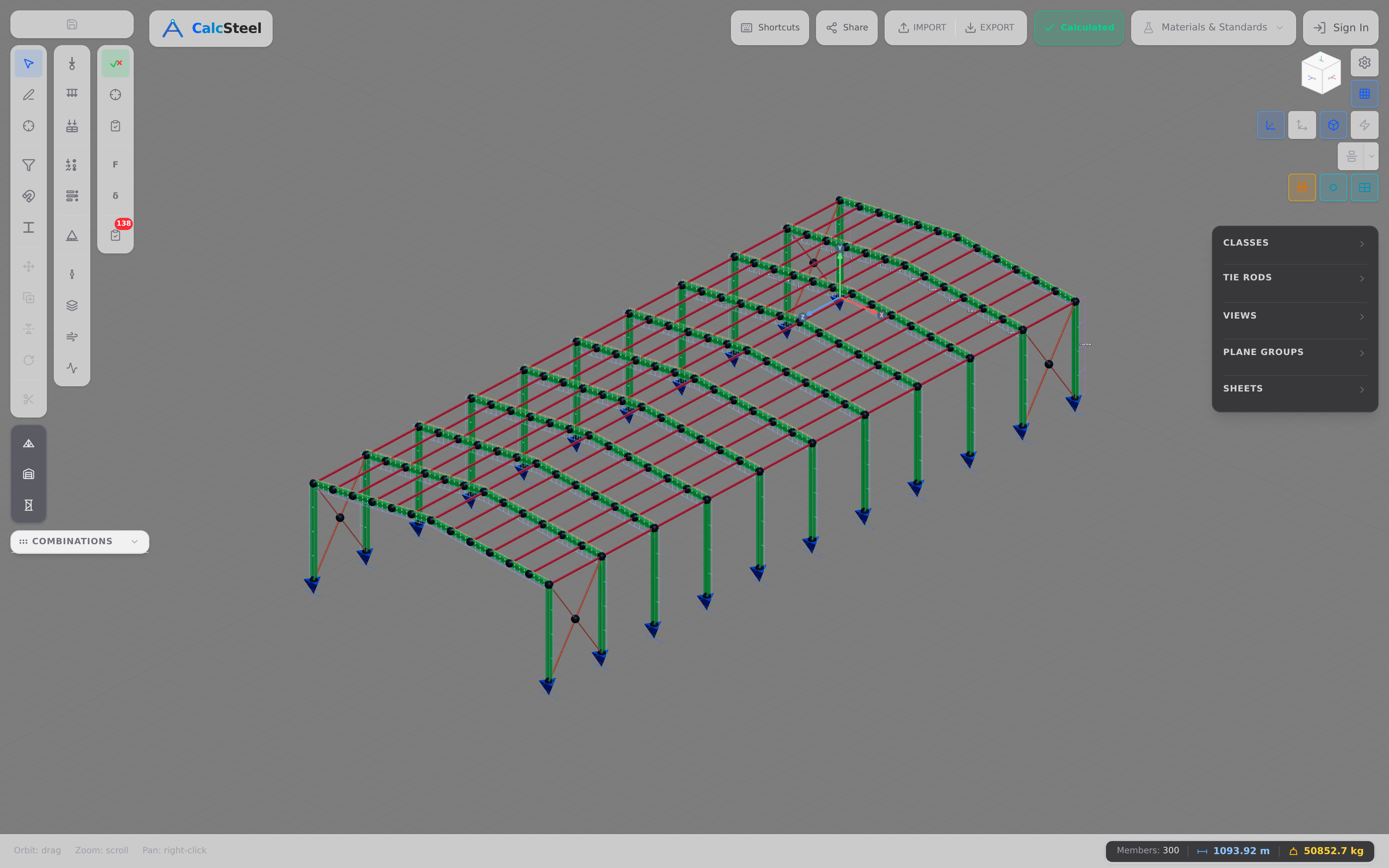
When you run the wind combinations on a real model in CalcSteel, the verification colours make the weakest link obvious: the members and connections that the 0.9D + 1.0W and 1.2D + 1.0W cases push toward or past their capacity light up, so you fix the actual governing element instead of guessing. On a hurricane coast, more often than not, the red is at a connection or a base, not in the middle of a beam.
From wind load to a sized member
A pressure is not a design. The path from a wind number to a steel section is short but strict: pick the governing combination, read the peak demand off the FEM run, then check that demand against the member's capacity. If utilization = demand / capacity < 1.0, the member passes. If not, you go up a size, change the section, or add bracing. That single ratio is what every wind calculation is really chasing.
Each part of the frame is governed by a different combination, and the three worked examples above already showed which one:
- The girt or purlin is sized for the bending it sees under wind pressure or wind suction. In Worked example 1, the 1.287 kN/m2 windward pressure over a 1.5 m tributary width gave Mmax = 8.69 kN·m on a 6 m span; that moment, not gravity, sets the girt. On leeward and side walls the same member must also be checked for suction, which reverses the sign and puts the other flange in compression.
- The column is governed by combined axial + bending under 1.2D + 1.0W. In Worked example 2 the wind barely touched the rafter's peak moment (257.7 kN·m falling to 254.2 kN·m) but unbalanced the base moments from left to right, taking the leeward column base to +34.3 kN·m while it still carries its share of the 120 kN of gravity. Axial force and bending moment acting together is exactly the interaction check covered in combined axial and bending, and it is why wind governs the columns rather than the beam.
- The anchors and base plate are governed by net uplift under 0.9D + 1.0W. In Worked example 3 that combination flipped the roof beam reactions to −9.6 kN, meaning every support connection is pulled up and the anchor rods go into tension. Members can be perfect and the building still fails here if the anchorage is not sized for that pull.
In the CalcSteel FEM engine this is not three separate hand checks. You define the load cases once, the solver builds the ULS and SLS combinations, and every member is classified and verified automatically against your chosen code: AISC 360, Eurocode 3 (EN 1993) or NBR 8800. The engine handles section classification, the flexural and axial resistances, and the interaction equations, then colours each member by its governing utilization so you see at a glance which element the wind combination pushes hardest. The numbers behind that picture are the same 8.69 kN·m, 34.3 kN·m and −9.6 kN you just followed by hand: nothing is hidden, everything is checkable.
The takeaway for sizing: do not size a member for a single combination and assume it covers the rest. The girt wants maximum pressure, the column wants gravity plus wind together, and the anchorage wants minimum dead load with full wind. Miss one and you have sized the wrong thing for the wrong case.
Common mistakes & FAQ
Wind is where careful engineers still get caught, because the dangerous case is rarely the obvious one. Here is the checklist we run through before trusting any wind design.
- Forgetting internal pressure (GCpi). The ±0.18 internal pressure coefficient can add or relieve load on every wall and the roof. On an enclosed building it swings the net roof uplift noticeably; on a partially enclosed one it is far larger. Leaving it out quietly under-designs the roof.
- Ignoring uplift and checking only gravity. Gravity feels intuitive, so it gets all the attention. But Worked example 3 showed the roof beam moment flipping from +32.0 kN·m sagging to −19.2 kN·m hogging under wind. A gravity-only check never sees that reversal, and that reversal is what peels roofs off.
- Treating the frame as pinned, so drift is missed. Model the bases as pins and the sway story disappears. The fixed-base portal in Worked example 2 drifted 1.08 cm (H/555); a sloppy or over-flexible model can blow straight through a typical H/400 to H/500 wind limit while every member still looks fine. Drift is a serviceability failure that member checks do not catch (see deflection and drift limits).
- Skipping the 0.9D + 1.0W combination. This is the case that minimises the helpful dead load and maximises wind, and it is the only one that reveals net uplift and overturning. If it is not in your combination set, your anchors and holddowns are effectively unchecked.
- Designing members but not the connection load path. A perfectly sized rafter is useless if the roof-to-rafter clip or the base anchor fails first. Wind is a load-path problem: roof to rafter to column to foundation, and the weakest link governs.
- Confusing service wind with factored wind. Drift and comfort checks use serviceability (unfactored or reduced) wind; strength checks use factored combinations. Mixing them either over-designs the frame or under-checks the drift.
How do you calculate wind load on a building?
Start with the velocity pressure. In ASCE 7-22, qz = 0.00256 · Kz · Kzt · Kd · Ke · V2 (V in mph, result in psf). For our warehouse that gave qz = 31.26 psf = 1.497 kN/m2. Then apply the gust factor and pressure coefficients: p = q(G·Cp − GCpi), which produced a windward-wall design pressure of 1.287 kN/m2 and a roof uplift of 1.414 kN/m2. Finally turn those pressures into line loads on your members and run the combinations. The free load-combination calculator handles the combination bookkeeping for you.
What wind speed do I design for?
You do not choose it, the code and the site choose it. ASCE 7 gives risk-category wind-speed maps; a hurricane-prone coast like our example lands on a basic wind speed of V = 130 mph (58.1 m/s). Eurocode uses a basic wind velocity vb from national maps, and NBR 6123 uses a basic wind speed V0. Always pull the design speed from the governing code and the building's risk category, never from a rule of thumb.
Why does the roof lift off in a hurricane?
Because wind over a low-slope roof creates suction, not pressure. In Worked example 3 the 0.9D + 1.0W combination produced a net upward line load of −2.4 kN/m: the wind uplift overpowered the reduced dead load, the beam reactions flipped to −9.6 kN of net uplift, and the connections went into tension. If the anchors and holddowns cannot resist that pull, the roof leaves the building. That is the exact mechanism, and it is why the 0.9D + 1.0W combination exists.
ASCE 7 vs Eurocode wind, are they really different?
Same physics, different bookkeeping. All three major codes start from dynamic pressure (roughly ½ρV2) and adjust for terrain, height, gusting and shape. ASCE 7-22 works in mph and psf with K-factors; EN 1991-1-4 builds a peak velocity pressure qp from a basic velocity vb and terrain categories; NBR 6123 uses V0 with S1·S2·S3 factors and q = 0.613·Vk2. The pressures land in the same ballpark; the coefficients and factor names differ. The CalcSteel combination tool covers ASCE 7, EN 1990 and NBR 8681 side by side so you can compare them directly.
Key takeaways
Wind load calculation is a straight line from an atmospheric pressure to a sized steel member, and every step in that line is checkable. Here is what to carry away.
- It all starts with velocity pressure. qz = 0.00256 · Kz · Kzt · Kd · Ke · V2. For a 130 mph coastal site that was 31.26 psf = 1.497 kN/m2, becoming 1.287 kN/m2 of windward pressure and 1.414 kN/m2 of roof uplift once gust and pressure coefficients were applied.
- Wind rarely governs the beam, but it governs everything around it. In the portal frame it barely moved the rafter peak (257.7 to 254.2 kN·m) yet multiplied sidesway drift about 330 times (0.003 to 1.08 cm, H/555) and unbalanced the base moments side to side. Only a real FEM run on a statically indeterminate frame captures that.
- Uplift is the killer. Under 0.9D + 1.0W the roof beam moment flipped from +32.0 kN·m sagging to −19.2 kN·m hogging and the reactions reversed to −9.6 kN of net uplift, putting connections into tension. That reversal is how hurricanes peel roofs off, and it is why the 0.9D + 1.0W combination exists.
- The load path decides survival. Roof to rafter to column to foundation: size the members, then size the connections and anchors for the same wind, because the weakest link governs.
- Design is one number: utilization < 1.0. Demand from the governing combination over code capacity (AISC 360, Eurocode 3 or NBR 8800), computed automatically once the model and loads are in.
Want to see it for yourself? The load-combination calculator builds your ULS and SLS combinations for ASCE 7, EN 1990 and NBR 8681 with the wind factors broken out, free and with no login. From there, drop the same frame into the full CalcSteel editor and let the FEM engine run the drift, uplift and interaction checks end to end.
CalcSteel is a genuinely free, browser-native structural steel design and analysis solution: a real FEM engine plus a suite of free calculators, no trial clock and no credit card. Students get it free through CalcSteel for Education. Model the frame, apply the wind, and watch which members the hurricane combination lights up. The best way to trust these numbers is to reproduce them.
Sources
- 1.ASCE/SEI 7-22: Minimum Design Loads and Associated Criteria for Buildings and Other Structures (Ch. 26-30, Wind Loads)
- 2.EN 1991-1-4:2005: Eurocode 1, Actions on structures, Part 1-4: Wind actions
- 3.ABNT NBR 6123: Forças devidas ao vento em edificações
- 4.FEMA P-499: Home Builder's Guide to Coastal Construction (wind uplift and load path)
Try CalcSteel for free
Model, analyze and design steel structures in your browser. No install, no signup.
Open the 3D editor