True Strain Formula: ε = ln(1 + e), and Where It Shows Up on a Real Steel Frame
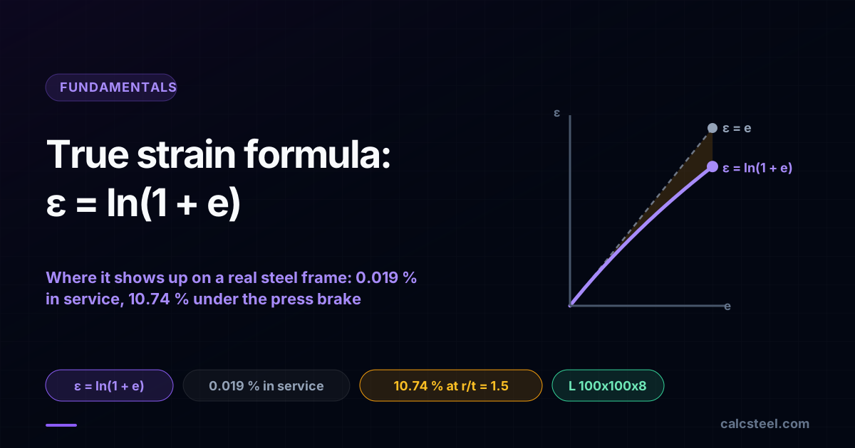
The true strain formula is ε = ln(L/L₀) = ln(1 + e). It exists because engineering strain has two defects: strains measured one after another do not add up, and a stretch is not the mirror image of the equal squash. A logarithm fixes both. The honest answer to when a steel designer needs it is narrow, and worth knowing precisely: on a real braced bay solved by the CalcSteel engine the two strains differ by 0.019 %, which is half a micron over a 7.2 m diagonal, while the same steel cold bent to the minimum radius puts them 10.74 % apart.
Key takeaways
- The true strain formula is ε = ln(L/L₀) = ln(1 + e). It measures each increment of stretch against the length the member has at that instant, instead of against the length it started with, which is what engineering strain does.
- Two properties follow, and engineering strain has neither. True strains measured in sequence add exactly, and a stretch to twice the length (+0.693) is the exact mirror of a squash to half the length (−0.693), where engineering strain says +100 % against −50 %.
- Proved on the shipping engine: an L 100x100x8 diagonal pulled in two equal stages to 345.01 MPa. Adding the two engineering strains gives 1725.059 µε against a true value of 1725.803 µε, short by exactly e₁·e₂ = 0.744 µε. The two true strains add to 1724.315 µε, which is the answer to eleven decimal places.
- In the elastic design range the gap is negligible, and you can quantify how negligible: the shortfall is about half the strain itself. On the braced bay diagonal at 22.0 % of fy, engineering strain is 379.849 µε against a true 379.777 µε, a difference of 0.52 µm spread over the whole 7.2 m member.
- It stops being negligible the moment steel is cold formed or handed to a nonlinear solver. A plate bent to the AISI RP98-1 floor of r/t = 1.5 reaches 25.0 % engineering strain on the outer fibre but only 22.31 % true strain, a 10.74 % gap at 145 times the yield strain.
The formula, and the honest answer to when you need it
Here is the whole thing, before any explanation:
εtrue = ln(L / L₀) = ln(1 + e)
where e = ΔL/L₀ is the ordinary engineering strain you already use. That is the true strain formula, also called logarithmic strain, natural strain or Hencky strain. It was first written down by Paul Ludwik in 1909, in a 59 page monograph about the mechanics of forming metal, and the reason it comes from a forming book rather than a structures book is the whole point of this article.
Most articles on this formula stop at the algebra. This one answers the question a structural engineer actually has, which is whether any of it changes a number on a drawing. The answer is specific and it has two halves. In the elastic range where you design, the difference between the two strains is 0.019 % on a real braced bay, which is half a micron over a 7.2 m diagonal, and you should ignore it deliberately rather than by accident. In cold forming, in a nonlinear finite element model and in the coupon test that fed that model, the difference runs from 2 % to 14 %, and ignoring it there corrupts the analysis.
Both halves are computed below on the real CalcSteel engine, on a braced bay you could actually build.
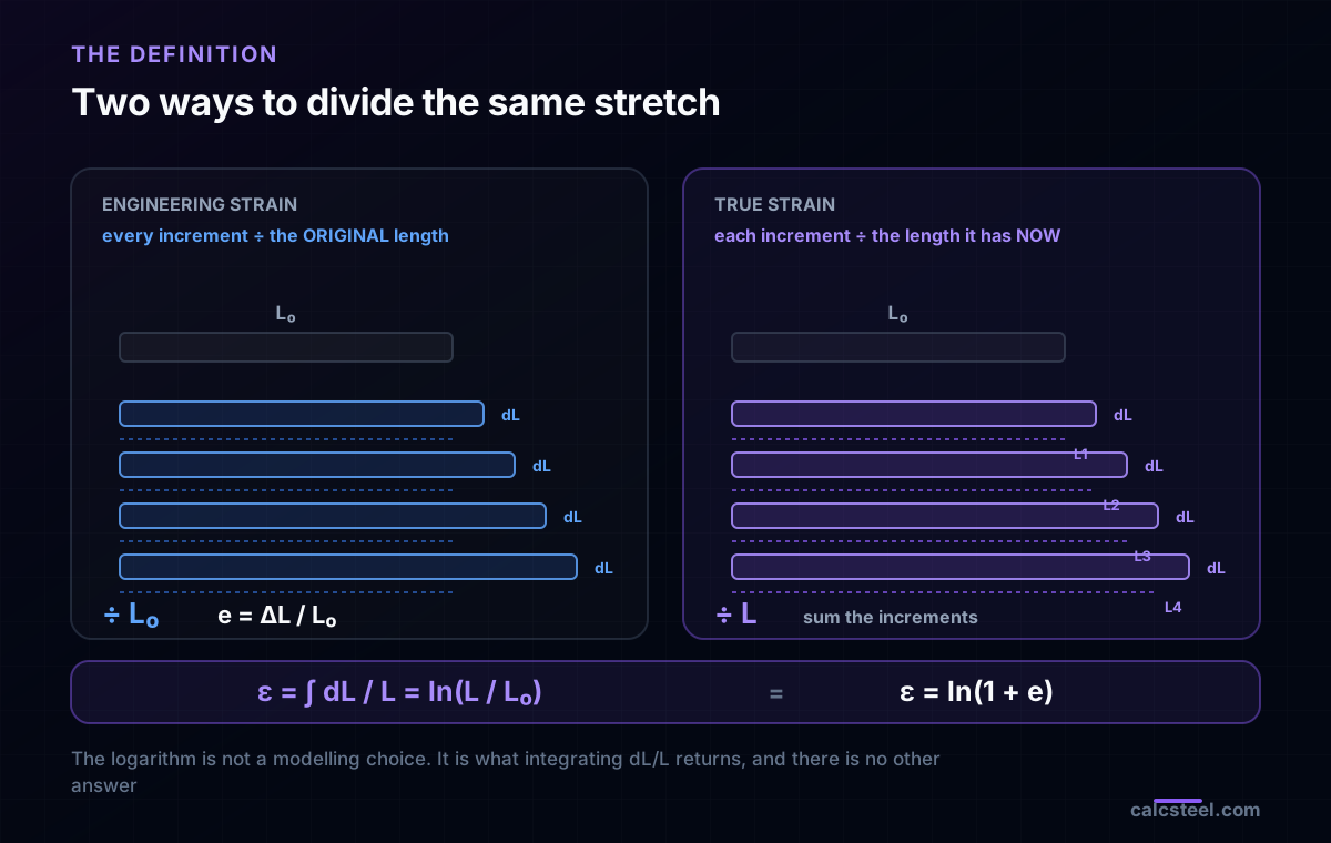
Why the definition needs an integral
Engineering strain has one reference length and never lets go of it:
e = (L − L₀) / L₀ = ΔL / L₀
Every millimetre of stretch, the first one and the ten thousandth, is divided by the same original L₀. That is a choice, not a law, and it is a very good choice while the stretch is small. It becomes a bad choice once the member is visibly longer than it started, because you are still measuring against a length the member no longer has.
True strain makes the other choice. It measures each increment against the length in front of it at that moment:
dε = dL / L
That is an increment, not a strain, so to get the strain you have to add the increments up. They are infinitesimal, so adding them up is an integral:
ε = ∫L₀L dL / L = ln(L) − ln(L₀) = ln(L / L₀)
The logarithm is not a modelling assumption anyone chose. It is what falls out of integrating dL/L, and there is no other answer. Ludwik called the result the effective specific elongation; today it is the true strain.
The true strain formula, in the three forms you will meet
The same quantity is written three ways, and they are all the same equation:
| Form | Formula | Use it when |
|---|---|---|
| From the two lengths | ε = ln(L / L₀) | you measured the bar before and after |
| From engineering strain | ε = ln(1 + e) | you have a stress-strain table in engineering terms |
| From the areas | ε = ln(A₀ / A) | the volume is constant, which is true once it yields |
Going the other way is just as clean. If you have a true strain and want the engineering strain back:
e = eε − 1
One substitution to fix it in place. A tension coupon of A572 grade 50 reaching first yield stretches by e = fy/E = 345 / 200,000 = 0.001725, that is 1725 µε. The true strain is ln(1.001725) = 0.00172351, that is 1723.5 µε. The two numbers agree to three significant figures and part company in the fourth, and that ratio is the entire story of the elastic range.
Note what the third form implies. Once you can write ε = ln(A₀/A) you no longer need to measure a length at all, only the neck of the specimen. That is exactly how true strain is recovered from a coupon after the bar has started to neck and the gauge length has stopped meaning anything.
The property engineering strain does not have
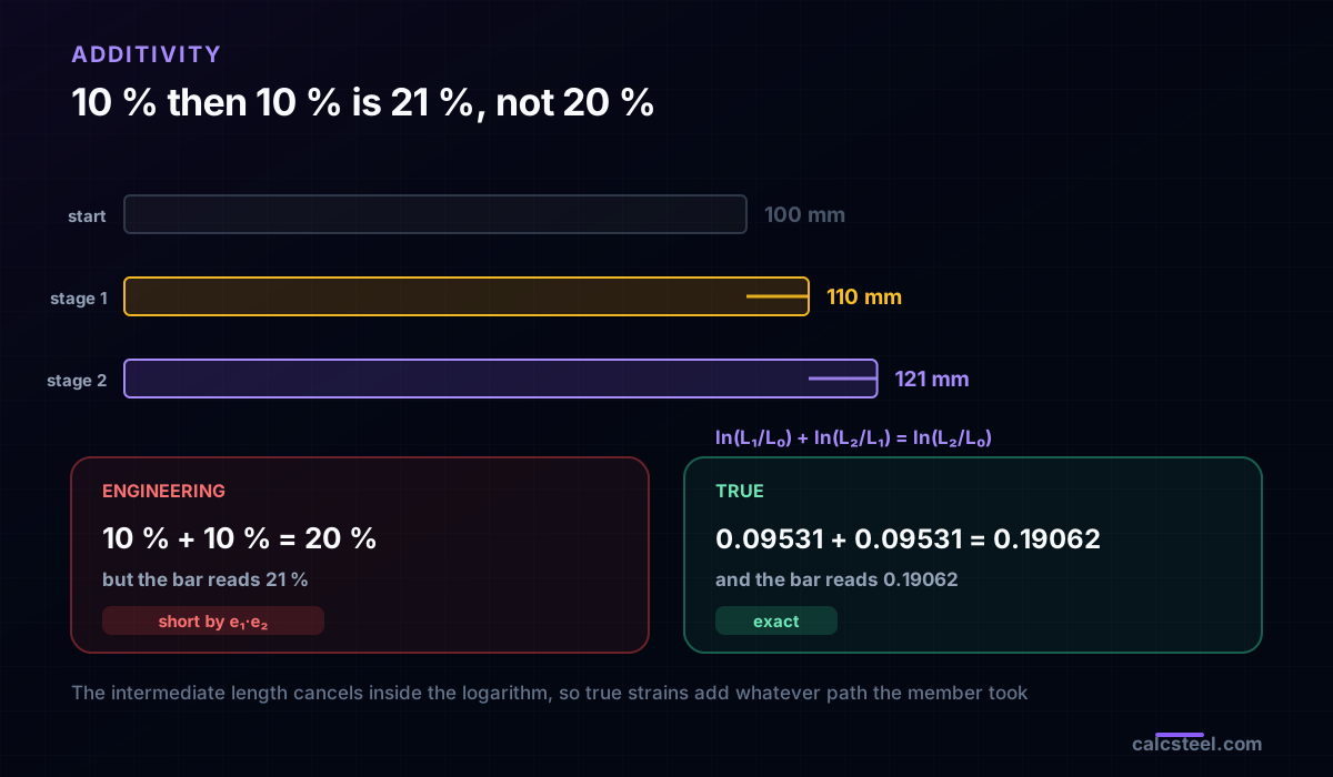
Take a 100 mm gauge length and stretch it by 10 %. It is now 110 mm. Stretch it by 10 % again, which is 11 mm this time, and it is 121 mm.
You applied 10 % and then 10 %. Ask what the total engineering strain is and the answer is not 20 %. It is (121 − 100)/100 = 21 %. The two engineering strains you measured refuse to add, and they are off by 4.762 % of the answer.
| Stage 1 | Stage 2 | Sum | Measured over the whole | |
|---|---|---|---|---|
| Length | 100 to 110 mm | 110 to 121 mm | 100 to 121 mm | |
| Engineering strain | 10 % | 10 % | 20 % | 21 % |
| True strain | 0.09531 | 0.09531 | 0.19062 | 0.19062 |
The true strains add. Not approximately, exactly, and for a reason that is visible in one line of algebra:
ln(L₁/L₀) + ln(L₂/L₁) = ln(L₂/L₀)
The intermediate length cancels. Whatever path the member took to get from L₀ to L₂, and however many stages you chopped it into, the true strains sum to the same total. Engineering strains cannot do this because each one carries a different reference length hidden inside it.
The size of the failure is exactly e₁·e₂: (1 + e₁)(1 + e₂) = 1 + e₁ + e₂ + e₁e₂. That is a second order term, which is why the failure is invisible at structural strains and fatal at forming strains. We measure it on the engine further down, and it comes out at 0.744 µε.
Tension and compression, finally symmetric
Here is the second defect, and it is the one that makes plasticity impossible to write in engineering strain.
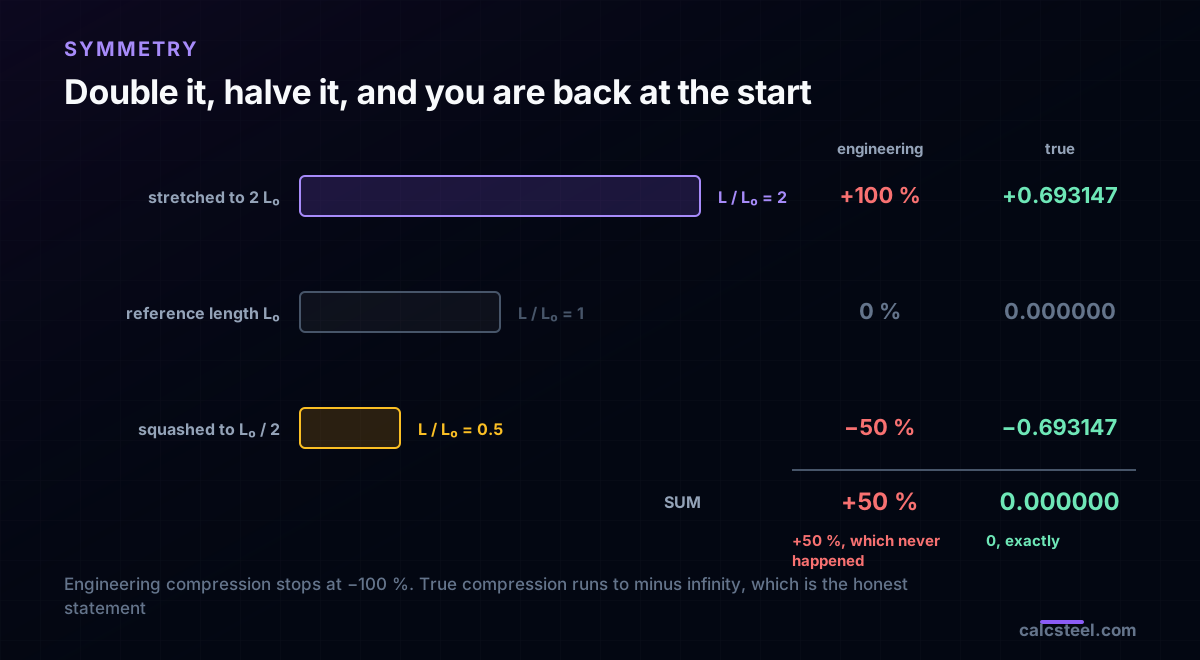
Take a bar and stretch it to twice its length. Take an identical bar and squash it to half its length. By any reasonable reading those are equal and opposite deformations. Engineering strain disagrees:
| Deformation | L / L₀ | Engineering strain | True strain |
|---|---|---|---|
| Stretch to double | 2.0 | +100 % | +0.693147 |
| Squash to half | 0.5 | −50 % | −0.693147 |
| Sum | 1.0, back to the start | +50 % | 0.000000 |
Do both to the same bar and you end up exactly where you started. True strain records that correctly, as +ln 2 followed by −ln 2, summing to zero. Engineering strain records a residual +50 %, which corresponds to nothing that happened.
There is a hard limit hiding in the same asymmetry. Engineering compressive strain can never go past −100 %, because the length cannot go below zero. True compressive strain runs to minus infinity as the length approaches zero, which is the physically honest statement: squashing something flat takes unbounded deformation, not 100 % of one.
Volume constancy, and why plasticity uses ν = 0.5
The third reason true strain exists is that it makes the constant volume condition trivial. Stretch a bar along 1 and let it contract along 2 and 3. In true strain, constant volume is:
ε₁ + ε₂ + ε₃ = 0
A clean sum of three numbers. The engineering-strain version of the same physical statement is (1 + e₁)(1 + e₂)(1 + e₃) = 1, a product, which nobody wants inside a yield criterion.
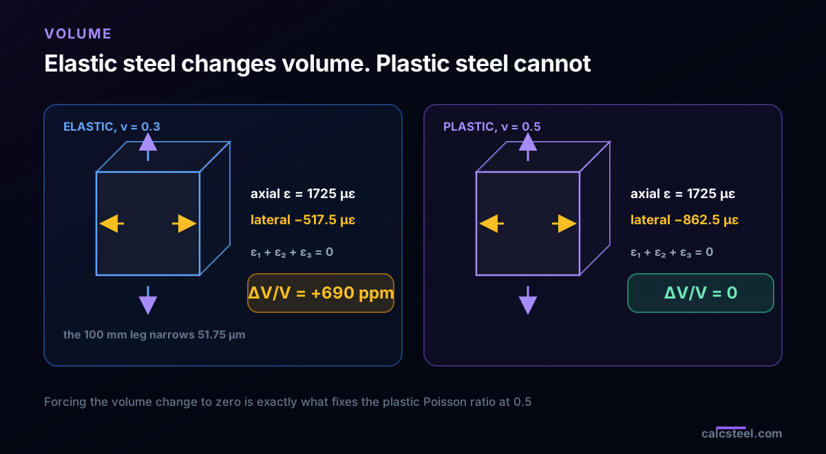
Steel does not conserve volume elastically. Take the engine's own axial case, the L 100x100x8 pulled to first yield at 1725 µε. With ν = 0.3 the transverse strain is −517.5 µε on each of the two lateral directions, so:
ΔV/V = ε(1 − 2ν) = 1725 × 0.4 = 690 ppm, that is +0.069 %
The angle is genuinely bigger in volume than it was, by seven parts in ten thousand, and its 100 mm leg has narrowed by 51.75 µm. Now push it past yield. Plastic flow in metal is a rearrangement of atoms, not a change in their spacing, so the volume stops changing. Set ΔV/V = 0 in the same equation and you get ν = 0.5, which is why every plasticity model quotes a Poisson ratio of 0.5 while the elastic part of the same model quotes 0.3.
That is not two contradictory material properties. It is one material with an elastic response that changes volume and a plastic response that cannot.
How big is the gap? About half the strain itself
Expand the logarithm as a series and the whole question answers itself:
ln(1 + e) = e − e²/2 + e³/3 − ...
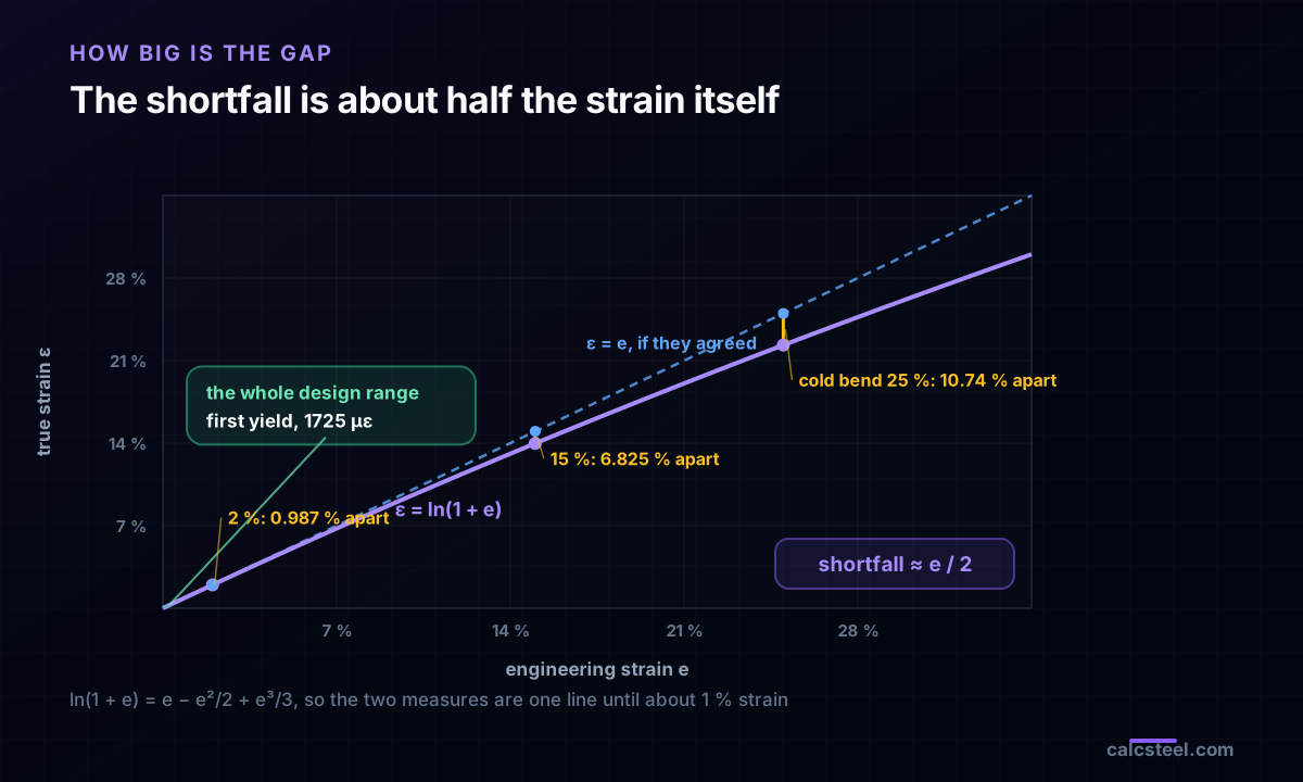
So the true strain falls short of the engineering strain by e²/2, and as a fraction of the strain that shortfall is e/2. A strain of 0.2 % is understated by about 0.1 % of itself. A strain of 20 % is understated by about 10 % of itself. One rule covers the whole range, and it is accurate to better than a fiftieth of a percent up to 2 % strain:
| Where you are | Engineering strain e | True strain ε | Shortfall |
|---|---|---|---|
| Braced-bay diagonal, service | 379.8 µε | 379.8 µε | 0.019 % |
| First yield, fy = 250 MPa | 1250.0 µε | 1249.2 µε | 0.062 % |
| First yield, fy = 345 MPa | 1725.0 µε | 1723.5 µε | 0.086 % |
| End of the yield plateau | 2.0 % | 1.9803 % | 0.987 % |
| Well into hardening | 5.0 % | 4.879 % | 2.42 % |
| Uniform elongation, near necking | 15.0 % | 13.976 % | 6.825 % |
| Cold bend at r/t = 1.5 | 25.0 % | 22.314 % | 10.74 % |
Read the table as a map of when to care. Everything above the yield line is a difference in the fourth significant figure of a number you rounded to three. Everything below the plateau line is a difference a reviewer would catch. The boundary sits at roughly 1 % strain, which is also, not coincidentally, the boundary where a linear elastic solver stops being the right tool.
Worked check, part 1: a real braced bay, and proving the engine first
Enough algebra. Here is a structure, and here is the engine that ships inside CalcSteel solving it.
A single braced bay, 6 m wide and 4 m high. IPE 300 rafter, HEB 200 columns, pinned bases, and one L 100x100x8 diagonal running from the bottom of the left column to the top of the right one, 7211.1 mm long. It carries 20 kN/m of gravity load on the rafter and a 100 kN lateral load at the eaves.
Before trusting a single strain out of it, the model has to prove itself two ways. First, global equilibrium: the sum of the horizontal reactions comes back as −100.000 kN against 100 kN applied, and the sum of the vertical reactions as 120.000 kN against the 20 × 6 = 120 kN applied. Exact, to every decimal the solver reports.
Second, the stiffness. Pulling the same L 100x100x8 axially with 270.3 kN, the engine returns an elongation of 6.21979 mm against the closed form NL/AE of 6.21979 mm, an error of 0.000004 %. Dividing the stress by that strain recovers E = 200,000 MPa from the displacement field rather than assuming it. The engine was never told what a strain is, and it just told us Young's modulus.
Now the numbers below mean something.
Worked check, part 2: the diagonal, and the 0.52 microns between the two strains
The engine reports 119.04 kN of tension in the diagonal, plus a small 1.357 kNm of bending it picks up from the joints. Over the 1566.9 mm² of an L 100x100x8 that is 75.97 MPa, which is 22.0 % of fy for A572 grade 50: an unremarkable, entirely realistic service stress.
| Quantity | Value | Where it comes from |
|---|---|---|
| Axial force in the diagonal | 119.04 kN | engine |
| Stress | 75.97 MPa | N / A |
| Elongation | 2.7391 mm | engine |
| Engineering strain e | 379.849 µε | σ / E |
| Same, from the moved node coordinates | 379.897 µε | engine geometry, 0.012 % apart |
| True strain ε | 379.777 µε | ln(1 + e) |
| Difference | 0.0721 µε | 0.019 % |
Two independent routes to the engineering strain agree to 0.012 %: one through Hooke's law from the element force, one purely geometric, measuring how far apart the engine moved the two end nodes. That agreement is what licenses the last row.
And the last row is the honest answer to the article's title. Converting to true strain changes this member's strain by 0.0721 µε. Spread over the whole 7211.1 mm diagonal that is a length of 0.52 µm, about a hundredth of the width of a human hair, on a member that stretched 2.7391 mm. No mill tolerance, no erection tolerance and no material certificate on earth is tight enough for that difference to be observable.
That is the correct result, not a disappointing one. It is why AISC 360, EN 1993-1-1 and NBR 8800 are all written in engineering strain and never mention the logarithm: in the range those documents govern, the conversion is arithmetic noise.
Worked check, part 3: the engine proves the strains add
The additivity claim from earlier was made with round coupon numbers. It deserves a real measurement, so here it is on the same diagonal.
The member is pulled in two equal stages of 270.3 kN each, 172.51 MPa a stage, so it finishes at 345.01 MPa, which is first yield for A572 grade 50 and the last point where a linear solver is still telling the truth. The catch is that a linear engine does not update its own geometry, so the second stage was solved on a model rebuilt at the length the first stage left behind. That is an explicit updated-Lagrangian step, done by hand, and it is the only way to ask the question honestly.
| Step | Length | Engine elongation |
|---|---|---|
| Start | 7211.1026 mm | |
| Stage 1, 270.3 kN | 7217.3223 mm | 6.21979 mm |
| Stage 2, 270.3 kN on the new length | 7223.5475 mm | 6.22515 mm |
Notice the second elongation is larger, 6.22515 against 6.21979 mm, from the identical force. The member got longer, so the same stress buys more stretch. That is the whole reference-length problem in one line.
| Stage 1 | Stage 2 | Sum | Measured start to finish | Error | |
|---|---|---|---|---|---|
| Engineering strain | 862.530 µε | 862.529 µε | 1725.059 µε | 1725.803 µε | 0.744 µε |
| True strain | 862.158 µε | 862.157 µε | 1724.315 µε | 1724.315 µε | 7.2 × 10⁻¹¹ µε |
The engineering strains are short by 0.744 µε, which is 0.0431 % of the answer, and that number is not approximately e₁·e₂, it is e₁·e₂ to every decimal the arithmetic carries. The true strains agree to the eleventh decimal place, which is the solver's own round-off and nothing else.
Theory said the residual would be the product of the two strains. The engine, which knows nothing about logarithms, produced exactly that.
See it yourself: get a stress from a frame, convert it to true strain
The portal frame calculator below runs live in this page. Set a span, a height, a load and a section, and read the elastic combined stress it reports for the column. Then do the conversion by hand, which takes two steps:
- e = σ / E, with E = 200,000 MPa (29,000 ksi). A stress of 150 MPa gives e = 0.00075, that is 750 µε.
- ε = ln(1 + e). ln(1.00075) = 0.00074972, that is 749.72 µε.
Push the load until the frame is near its capacity and watch what does not happen: the gap stays in the fourth significant figure. You cannot make these two numbers disagree with a load case, because in the elastic range they only disagree by e/2 and e is small by definition. The only way to separate them is to leave the elastic range entirely, which is the subject of the next two sections.
Diagrams plotted on the deformed-free frame geometry. N, V, M recovered from the element end-forces of the direct-stiffness solve (12 elements / member). Moment drawn offset to each member's centreline.
First-order STRENGTH screening at the governing section of the NBR 8800 (BR) ULS envelope (governing CB2): N,d = 73.9 kN, M,d = 109 kN·m. Member buckling and lateral-torsional buckling are NOT included — see the stability flags below and run the full verification in the 3D editor. Click a card to make that resistance code govern the ranking.
ULS load combinations — NBR 8800 (BR)
G + W superposed · 3 combinations| Combination | Factors | Utilization |
|---|---|---|
| CB1 | 1.4 G | 69% |
| CB2governs | 1.4 G + 1.4 W | 76% |
| CB3 | 1 G + 1.4 W | 57% |
Combinations generated by the CalcSteel combinations engine (the same v4 engine the 3D editor uses, 6 codes). Gravity is treated as a single permanent action G; the wind action W is the eaves load. Each combination's γ factors are applied by superposition to the isolated gravity and wind solves, then every section is screened — the worst point of the worst combination governs.
Stability screening (buckling caveats)
not in the strength checkScreening indicators only — assumed sway effective length (K = 1.5) and the full member length as the unbraced length (no intermediate purlin/girt restraint). The strength check above deliberately excludes these; the real member verification (effective lengths from the alignment chart / notional loads, χ and Cb reduction factors, purlin bracing) runs in the 3D editor.
Lightest sections that pass (NBR)
screened 974 profiles| Profile | Mass | Frame steel | Utilization | |
|---|---|---|---|---|
| VS 400x32 | 31.9 kg/m | 723 kg | 82% | |
| VS 350x33 | 33.2 kg/m | 752 kg | 86% | |
| VS 400x34 | 34.4 kg/m | 779 kg | 75% | |
| VS 350x35 | 35.1 kg/m | 795 kg | 80% | |
| VS 400x35 | 35.1 kg/m | 795 kg | 73% |
Where it shows up (1): the plate you cold bend
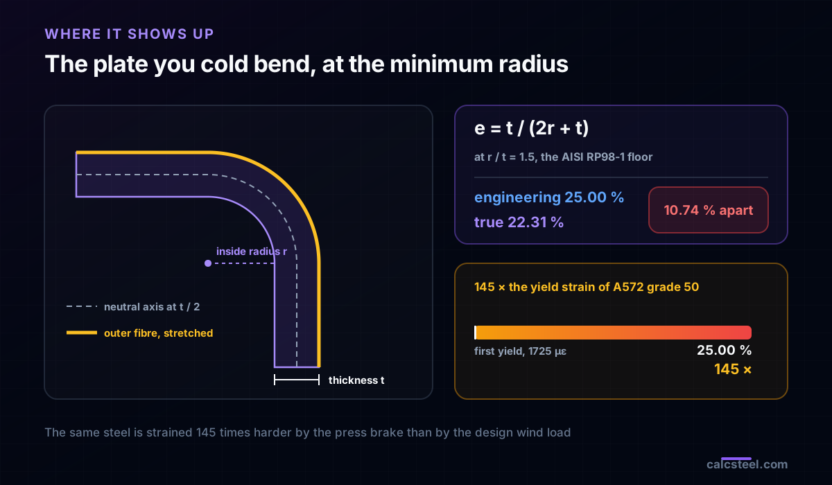
This is the one that lives on real fabrication drawings. Every bent gusset, every folded base plate, every cold-formed cladding rail takes a plate and wraps it around a radius. The outer fibre has to travel further than the middle of the plate, and if the neutral axis sits at mid thickness the engineering strain it reaches is:
e = t / (2r + t) = 1 / (2(r/t) + 1)
with r the inside bend radius and t the plate thickness. That formula is the one the AISI and AISC cold-bending guidelines use to decide whether a bend will crack, by comparing it against the steel's fracture strain. Here is what it gives, and what the true strain is at each point:
| r / t | Engineering strain | True strain | Shortfall | Times the yield strain |
|---|---|---|---|---|
| 1.0 | 33.33 % | 28.77 % | 13.70 % | 193 |
| 1.5 | 25.00 % | 22.31 % | 10.74 % | 145 |
| 2.0 | 20.00 % | 18.23 % | 8.84 % | 116 |
| 2.5 | 16.67 % | 15.42 % | 7.51 % | 97 |
| 3.0 | 14.29 % | 13.35 % | 6.53 % | 83 |
| 5.0 | 9.09 % | 8.70 % | 4.29 % | 53 |
| 10.0 | 4.76 % | 4.65 % | 2.31 % | 28 |
Two of those rows are code numbers, not illustrations. AISI RP98-1, the Brockenbrough cold-bending study republished in 2022, sets an absolute practical floor of r/t = 1.5 for cold forming plate and lists 1.5t as the suggested minimum inside radius for A572-50 up to 3/4 in. thick. The AISC Manual is more conservative for that grade at 1/4 and 1/2 in., at r/t = 2.5. So the two rows a fabricator actually works to are the 25.00 % and the 16.67 % ones, where the two strain measures are 10.74 % and 7.51 % apart.
Put that next to the braced bay. The same steel, in the same building, is strained 145 times harder by the press brake than by the design wind load, and the strain measure you use stops being a detail.
Where it shows up (2): the curve you feed a nonlinear solver
The second place is a settings dialogue, and getting it wrong is silent.
A nonlinear finite element solver integrates equilibrium over the deformed shape, so the stress it wants is force over the real, shrinking area and the strain it wants is logarithmic. Abaqus, ANSYS and every general purpose code documents this the same way: the plastic material table takes true stress against true plastic strain. The conversion from the numbers a coupon test produced is three lines:
- σtrue = σeng(1 + e)
- εtrue = ln(1 + e)
- εplastic = εtrue − σtrue/E
Skip them and paste the engineering curve straight in, and the solver reads the fall-off after the ultimate stress as the steel getting weaker. Real steel never softens; the engineering curve only turns down because the area is shrinking faster than the load is rising. A model told that steel softens will localise a plastic hinge at whichever element happened to yield first and report a collapse load that is too low, for a reason nothing in the output will point at.
The magnitudes are the ones from the table above. At the 15 % uniform elongation of a typical grade 50 coupon, the true strain is 13.976 % rather than 15 %, a 6.825 % error in the abscissa of every hardening point you enter. The same coupon is where the conversion has to happen anyway: once the bar necks, the strain is no longer uniform over the gauge length and the only honest measurement left is ε = ln(A₀/A) at the neck.
Eurocode 3 part 1-5 Annex C, which governs finite element modelling of steel structures, is explicit that the material model has to match the strain measure the analysis uses. Seismic work lands in the same place from the other direction: a ductility demand quoted as 2 % strain is 1.9803 % in true terms, 1 % out, which is inside the noise of a strain gauge but not inside the noise of a low-cycle fatigue model that raises strain to a power.
Six ways this goes wrong in practice
1. Converting in the elastic range and calling it rigour. Below yield the conversion changes the fourth significant figure. On the braced bay it is 0.52 µm over a 7.2 m member. Doing it does not make a design safer, it makes a report longer.
2. Not converting when the strain is over about 1 %. The same conversion that is noise at 0.17 % is 6.825 % at 15 %. Cold forming, nonlinear FE and coupon post-processing are all above the line.
3. Adding engineering strains from separate stages. Two 10 % stages are 21 %, not 20 %. On the engine, two elastic stages land 0.744 µε short, which is exactly e₁·e₂, so the error grows as the square of the strain.
4. Using ε = ln(A₀/A) before the steel yields. That form assumes constant volume, which is only true in plastic flow. In the elastic range ν is 0.3, the volume grows by 0.069 % at first yield, and the area route gives the wrong answer.
5. Pairing true strain with engineering stress. The two conversions are separate and both are needed. A curve of σeng against εtrue is not a material property of anything; it is a half-finished conversion.
6. Assuming code strain limits are true strains. They are not. Elongation at rupture on a mill certificate, the 15 % or 21 % in the specification, is engineering strain over a stated gauge length, and comparing it against a true strain out of a finite element model understates the demand by about half the strain.
The short version: the true strain formula is ε = ln(1 + e), it is worth understanding because it explains why plasticity is written the way it is, and on the elastic frame you are designing today it will change nothing. Which of those two facts matters depends entirely on whether the steel in front of you is being analysed or being bent.
Sources
- 1.Ludwik, P., Elemente der Technologischen Mechanik, Springer Berlin 1909 (the first statement of logarithmic strain as the integral of dL/L)
- 2.Brockenbrough, R. L., Fabrication Guidelines for Cold Bending, AISI RP98-1 (republished 2022): the outer fibre strain t/(2r + t) and the Table 7 minimum inside bend radii
- 3.AISC Engineering Journal, Development of Fabrication Guidelines for Cold Bending of Plates (the test programme behind the r/t limits)
- 4.AISC 360-16, Specification for Structural Steel Buildings (E = 29,000 ksi, fy and fu defined on the original cross-section)
- 5.Eurocode 3 (EN 1993-1-5, Annex C), material modelling for finite element analysis of steel structures
- 6.ASTM A370 / ASTM E8-E8M, Standard Test Methods for Tension Testing of Metallic Materials (elongation at rupture as an engineering strain over a stated gauge length)
- 7.Dieter, G. E., Mechanical Metallurgy (true stress-strain, the additive property of logarithmic strain and constant-volume plastic flow)
Try CalcSteel for free
Model, analyze and design steel structures in your browser. No install, no signup.
Open the 3D editor