Thermal Strain in Restrained Members: The Force a Steel Beam Develops When It Cannot Expand
Heat a steel beam and it wants to grow. An IPE 300 spanning 6 m gains 2.88 mm over a 40 °C rise, a movement you could catch with a caliper. Now hold both ends still. Those 2.88 mm have nowhere to go, and the beam answers with 516.6 kN of compression and 96 MPa of stress, from temperature alone, with no load on it at all. This is thermal strain in restrained members: the strain the steel cannot express turns into force. And the strangest part, checked against the CalcSteel FEM engine below, is that the force does not care how long the beam is.
Key takeaways
- Free thermal strain is ε = α·ΔT. For structural steel α = 12 µε/°C, so every 1 °C stretches the steel by 12 parts per million, and a member of length L grows by α·ΔT·L.
- Restrain that expansion fully and the strain becomes stress: σ = E·α·ΔT. In steel that is exactly 2.4 MPa for every degree Celsius, independent of the section and of the length.
- The restraint force is N = E·A·α·ΔT. A 6 m IPE 300 heated 40 °C develops 516.6 kN of compression, engine-confirmed, with nothing else applied.
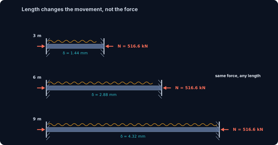
- Length changes the free movement, not the force. The same section at 3, 6 and 9 m develops the identical 516.6 kN; only the suppressed movement scales with L.
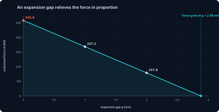
- The fix is to let it move: an expansion gap, a slotted hole or a sliding bearing. A 2.88 mm gap on the 6 m beam relieves the force to zero, and a partial gap relieves it in proportion.
The force that appears from nothing
Structural loads you can point to. Gravity pulls down, wind pushes sideways, a crane hangs its hook. Temperature is different: nothing pushes, nothing hangs, and yet a restrained member can carry a force larger than most of the loads you designed it for. It comes from a movement that is not allowed to happen.
Every material expands when heated, and steel expands generously enough to matter: a long beam in the sun, a pipe rack in a summer afternoon, a bridge girder between abutments. Left free, the member simply grows and nobody notices. Bolt it between two stiff supports and the same growth turns into stress, because the steel is now fighting to occupy space it is not permitted to reach.
This article follows that force from the coefficient of expansion to a worked IPE 300, checks every number against the shipping CalcSteel engine, and ends where the design actually lives: the detail that lets the member breathe.
Free thermal strain: the movement steel wants
Heat a bar and it stretches by a strain proportional to the temperature change. That is the whole of it:
ε = α·ΔT (free thermal strain), so δ = α·ΔT·L (free thermal movement).
Here α is the coefficient of thermal expansion. For structural steel it is 12 × 10⁻⁶ per °C, or 12 microstrain for every degree. Multiply by the length and you get the free movement. There is no stress yet: a bar free at one end lengthens, its atoms sit a little farther apart, and the internal force is exactly zero.
Put numbers on it. The IPE 300 we use through the article, spanning 6 m, heated by 40 °C: δ = 12 × 10⁻⁶ × 40 × 6000 mm = 2.88 mm. Almost three millimetres of growth. Hold that number, because everything that follows is the story of what happens when those 2.88 mm are refused.
Where α comes from, and why steel and concrete get along
The coefficient is a material property, measured rather than derived. It says how fast the lattice spacing grows with temperature, and it varies more between materials than most engineers remember:
| Material | α (µε/°C) |
|---|---|
| Structural steel | 12 |
| Stainless steel (austenitic) | 17 |
| Concrete | 11 |
| Aluminum alloy | 23 |
Two readings matter for steel design. First, stainless expands roughly 40 percent more than carbon steel, which is why a stainless component bolted into a carbon-steel frame can develop its own thermal fight even when the whole assembly is heated uniformly. Second, structural steel and concrete sit almost on top of each other, 12 against 11. That near match is what lets reinforced concrete and composite steel-concrete sections survive temperature swings: the two materials grow together and the bond is never asked to referee a large difference.
Aluminum, at nearly twice steel's value, is the cautionary tale. An aluminum member restrained the way our beam is would have far more movement to suppress, and the thermal force scales right along with it.
When it cannot move: strain becomes force
Now fix both ends. The beam still wants to grow by δ = α·ΔT·L, but the supports refuse every millimetre. Compatibility does the bookkeeping: the total change in length must be zero, so the mechanical shortening the member is forced into has to cancel the free thermal growth exactly.
Free thermal elongation minus the elastic shortening under the internal force N equals zero: α·ΔT·L − N·L/(A·E) = 0. Solve for N and the length cancels:
N = E·A·α·ΔT
That is the force the restraint must carry, and it is a compression: the member is being squeezed back into a length it would rather exceed. Divide through by the area and you get the stress:
σ = N/A = E·α·ΔT
Two cancellations are worth pausing on. The length L dropped out of N, and the area A dropped out of σ. Temperature does not produce a force that grows with the span, and it does not produce a stress that depends on how heavy your section is. It produces a stress fixed entirely by the material and the temperature change, and a force fixed by that stress and the area. The FEM engine agrees to the millimetre, as the next sections show.
The number to remember: 2.4 MPa per degree
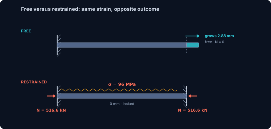
Put steel's numbers into σ = E·α·ΔT. With E = 200 GPa and α = 12 µε/°C:
σ = 200000 MPa × 12 × 10⁻⁶ × ΔT = 2.4 × ΔT (MPa)
Every degree Celsius of suppressed temperature change is 2.4 MPa of stress in fully restrained steel. That single constant lets you size the problem in your head before touching a calculator:
| Temperature rise ΔT | Restrained stress σ |
|---|---|
| 10 °C | 24 MPa |
| 20 °C | 48 MPa |
| 40 °C | 96 MPa |
| 50 °C | 120 MPa |
| 60 °C | 144 MPa |
| 100 °C | 240 MPa |
The design consequence lands fast. A 40 °C swing, well within what an exposed dark-painted beam sees between a winter night and a summer afternoon, is 96 MPa of compression with no load applied. For common MR250 or A36 steel with a 250 MPa yield, full restraint reaches yield at ΔT = 250/2.4 = 104 °C, and for S235 at 98 °C. Those are not fire temperatures. They are the gap between an erection morning and a bad afternoon, on a member that was detailed to move and then, somewhere, was not.
Worked example: an IPE 300 that cannot expand
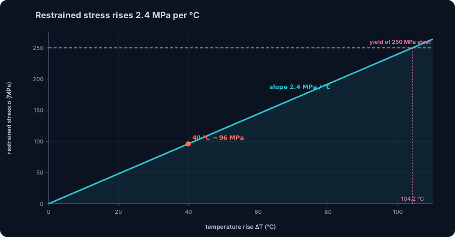
Take the IPE 300 concretely. The CalcSteel engine computes its area from the section geometry as A = 53.81 cm², matching the catalogue value. Span 6 m, both ends fully restrained against axial movement, temperature rise 40 °C.
- Free movement it wants: δ = α·ΔT·L = 12 × 10⁻⁶ × 40 × 6000 = 2.88 mm.
- Restrained stress: σ = 2.4 × 40 = 96 MPa (compression).
- Restrained force: N = σ·A = 96 MPa × 5381 mm² = 516.6 kN.
516.6 kN. That is the reaction each support must deliver, the axial thrust the connections must transfer, and the compression the member must carry, all from a temperature change and nothing else. To confirm it, we ran the shipping FEM engine on the same bar, applied the computed 516.6 kN, and read back an elongation of exactly 2.88 mm and a support reaction of 516.6 kN. The force that suppresses the free growth is precisely the force that would have produced it. That equivalence is the heart of restrained thermal action, and the engine reproduces it to the millimetre.
Why length changes the movement, not the force
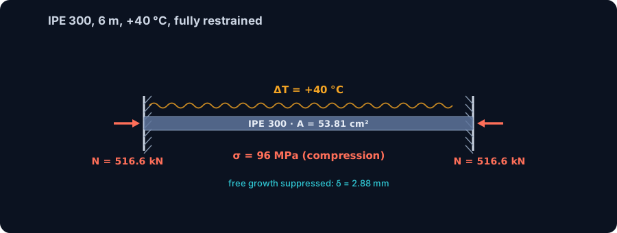
The result that surprises students every time: make the beam longer and the thermal force stays exactly the same. Run the same IPE 300 at 3, 6 and 9 m through the engine, all heated 40 °C:
| Length L | Free movement | Restrained force |
|---|---|---|
| 3 m | 1.44 mm | 516.6 kN |
| 6 m | 2.88 mm | 516.6 kN |
| 9 m | 4.32 mm | 516.6 kN |
The free movement doubles from 3 to 6 m and triples from 3 to 9 m, because δ = α·ΔT·L is proportional to length. The force does not move at all. It sits at 516.6 kN for every span, because N = E·A·α·ΔT never contained L in the first place. A longer member simply has more length over which to distribute the same locked-in strain, so it stores the same stress.
The intuition to carry away: temperature loads a member by strain, not by force. A 30 m truss chord restrained end to end does not develop thirty times the thermal thrust of a 1 m link. It develops the same stress, and the same force for the same area. Length shows up only in how much movement you would have had to accommodate to avoid the force entirely.
The compression has to go somewhere: thermal buckling
A restrained thermal force is a compression, and compression in a slender member raises a second question the stress alone does not answer: does it buckle before it yields? For our IPE 300 as a 6 m column, unbraced about its weak axis, the engine's section properties give a radius of gyration ry = 3.35 cm and a slenderness KL/ry = 179. The Euler critical load about that axis is
Ncr = π²·E·Iy / L² = π² × 200 GPa × 602.9 cm⁴ / (6 m)² = 331 kN.
The 40 °C restrained force, 516.6 kN, is 1.56 times that. The member does not climb to 96 MPa and stop; it buckles first. Worse, buckling arrives early: the compression reaches the 331 kN Euler load at a temperature change of only 25.6 °C. A slender restrained member can buckle from a mild warm afternoon, long before the stress looks alarming on paper.
This is why restrained thermal force is not merely a stress check. In a braced member the force is real but the buckling path is closed, so it flows into the connections and the supporting structure as a thrust. In an unbraced or lightly braced member the same force can find the buckling mode and take it. The live calculator below lets you put in a section and a length and see which case you are in.
Try it live: does the thermal force buckle your column?
Enter your section, your effective length and an axial force below. To connect it to this article, compute the restrained thermal force first, N = E·A·α·ΔT, or read the stress straight off the 2.4 MPa per °C rule and multiply by the area, then type that force in and compare it against the buckling capacity the calculator returns. If the thermal force sits above the curve, the member buckles under temperature alone. If it sits below, the force is still there, and your connections and supports have to carry it.
The calculator runs the same checks as the CalcSteel engine: the Euler critical load with the AISC 360 and NBR 8800 design capacities side by side, with the buckled shape and the effective length K·L drawn for your column.
End conditions (buckling case)
Pinned – Pinned
Cross-section
Slenderness KL/r
134.7
limit 200 · OK
Euler Pcr (elastic)
310.7 kN
Fe = 108.9 MPa
AISC 360 φcPn
245.2 kN
Fcr = 95.5 MPa · elastic
NBR 8800 Nc,Rd
247.7 kN
χ = 0.382 · λ₀ = 1.52
Code vs code — same column
Nc,Rd / φcPn = 1.010
Both codes share the 0.658 / 0.877 buckling curve — the ~1% gap is purely φc = 0.90 (AISC) vs 1/γa1 = 0.909 (NBR).
Demand check — Nd = 150 kN
Step-by-step derivation — live for YOUR column
IPE 200 · L = 3 m · K = 1 · fy = 250 MPa
- 1
Slenderness ratio
λ = K·L/r = 1 × 3000 / 22.28 mm
λ = 134.7 (≤ 200 ✓)
- 2
Euler elastic buckling stress and load
Fe = π²E/λ² = π² × 200,000 / 134.7² · Pcr = Fe·A = Fe × 2854 mm²
Fe = 108.9 MPa · Pcr = 310.7 kN
- 3
Buckling regime (AISC E3)
4.71·√(E/fy) = 4.71·√(200,000/250) = 133.2 < λ = 134.7
elastic buckling → use E3-3 (0.877·Fe)
Elastic range: capacity no longer depends on fy — only geometry (r, K, L) helps.
- 4
AISC 360 critical stress and design capacity
Fcr = 0.877 · Fe = 0.877 × 108.9 = 95.5 MPa · φcPn = 0.9 × Fcr × A
Pn = 272.5 kN · φcPn = 245.2 kN
- 5
NBR 8800 reduction factor and design capacity
λ₀ = √(fy/Fe) = 1.515 > 1.5 → χ = 0.877/λ₀² = 0.382 · Nc,Rd = χ·A·fy/1.1
Nc,Rk = 272.5 kN · Nc,Rd = 247.7 kN
Same 0.658/0.877 curve as AISC — the ~1% difference is φc = 0.90 vs 1/γa1 = 0.909.
Sections that work — 3 lightest of 612 catalog profiles carrying Nd = 150 kN at L = 3 m, K = 1
| Section | kg/m | φcPn (kN) | Nc,Rd (kN) | Util. | |
|---|---|---|---|---|---|
| lightestSHS 80x4 | 9.2 | 164 | 166 | 91% | |
| HSS 76x76x4.8 | 9.9 | 165 | 167 | 91% | |
| CHS 88.9x5 | 10.3 | 172 | 174 | 87% |
Pass criterion: φcPn ≥ Nd (AISC 360 LRFD) AND Nc,Rd ≥ Nd (NBR 8800) AND KL/r ≤ 200, using each section's tabulated-mass area and minimum radius of gyration.
Buckling curve — IPE 200, fy = 250 MPa
Capacity of IPE 200 by unbraced length — K = 1, fy = 250 MPa
| L (m) | KL/r | Pcr Euler (kN) | φcPn AISC (kN) | Nc,Rd NBR (kN) | Regime |
|---|---|---|---|---|---|
| 1 | 45 | 2,796 | 577 | 583 | inelastic |
| 2 | 90 | 699 | 419 | 423 | inelastic |
| 3◀ yours | 135 | 311 | 245 | 248 | elastic |
| 4 | 180 | 175 | 138 | 139 | elastic |
| 5 | 224 ⚠ | 112 | 88 | 89 | elastic |
| 6 | 269 ⚠ | 78 | 61 | 62 | elastic |
| 7 | 314 ⚠ | 57 | 45 | 45 | elastic |
| 8 | 359 ⚠ | 44 | 34 | 35 | elastic |
| 9 | 404 ⚠ | 35 | 27 | 28 | elastic |
| 10 | 449 ⚠ | 28 | 22 | 22 | elastic |
Real restraint is partial: the gap that lets the force out
Full restraint is the worst case, and it is also rare. Real supports give a little, and real details often leave a deliberate gap. Both relieve the force, and the arithmetic is simple: the member expands freely until it closes the gap, then locks only the movement that remains.
With a gap g, the suppressed movement is δ − g, and the force scales with what is left: N = E·A·(α·ΔT − g/L). On our 6 m IPE 300 at 40 °C, where the free movement is 2.88 mm, the engine confirms:
| Expansion gap g | Locked movement | Restrained force |
|---|---|---|
| 0 mm | 2.88 mm | 516.6 kN |
| 1.0 mm | 1.88 mm | 337.2 kN |
| 2.0 mm | 0.88 mm | 157.8 kN |
| 2.88 mm | 0 mm | 0 kN |
A 1 mm gap, a slotted hole or a slightly loose bolt, already sheds a third of the force. A gap equal to the full free movement, 2.88 mm, sheds all of it: the member reaches the end of its travel exactly as the temperature peaks and never develops a single kN. This is the whole design idea behind expansion details, and it is why the number to detail is not the force but the movement, δ = α·ΔT·L, the one quantity in this article that does grow with length.
Where this shows up on real jobs
The restrained-expansion force is not a textbook curiosity. It governs details across the whole of steel practice:
- Long beams and floor edges framed rigidly into stiff columns, where a summer temperature swing pushes the columns outward with the full thermal thrust.
- Bridges, the classic case, where expansion joints and sliding or rocker bearings exist for exactly this reason. A deck restrained end to end would drive enormous forces into the abutments.
- Crane rails and long runway girders, continuous over many metres, where accumulated expansion is taken up at planned breaks.
- Pipe racks and process structures, where the hot lines and the steel that carries them both move, and anchors and guides are placed to decide where the force is allowed to build.
- Fire, the extreme case, where ΔT is measured in hundreds of degrees. Restrained beams in a fire develop compressions that push columns and can fail connections long before the steel loses strength, which is why restrained thermal expansion sits at the centre of structural fire engineering.
What engineers do about it
The force comes from a movement that is refused, so every fix is a way to grant the movement or to plan for the force. In rough order of how often they appear:
- Let it move. Expansion joints, slotted holes, sliding bearings and one pinned end with one free end all give the member somewhere to grow. Size the gap to the free movement δ = α·ΔT·L for the temperature range you expect, with margin.
- Release one end. A member fixed at one end and free at the other develops no axial thermal force at all; it simply lengthens. Many connections are detailed precisely to stay axially free while still carrying shear.
- Design for the force. Where restraint is unavoidable, carry the thrust honestly: check the member for the combined thermal compression and its other loads, and check that the connections and supporting structure can take the reaction. Remember it is a compression, so buckling, not just yield, is on the table.
- Break the run. Long continuous structures are split into thermal blocks by movement joints, so that no single restrained length ever accumulates a large movement to fight over.
Five ways restrained thermal action gets mishandled
- Thinking longer members develop more force. They do not. The force is E·A·α·ΔT, with no length in it. Longer members develop more movement, which changes the detailing, not the force.
- Assuming a heavier section is safer against temperature. A bigger area carries more force, N = E·A·α·ΔT, at exactly the same stress, σ = E·α·ΔT. Upsizing does not lower the thermal stress; it can even raise the thrust into the supports.
- Checking stress and forgetting buckling. The thermal force is a compression. In a slender restrained member it can reach the Euler load well below yield, as our IPE 300 did at 25.6 °C.
- Using the wrong α. Stainless and aluminum expand markedly more than carbon steel. A stainless detail sized with steel's 12 µε/°C underestimates both the movement and, when restrained, the force.
- Detailing the force instead of the movement. You cannot economically design most connections for the full restrained thrust. The right move is almost always to design the gap: grant the δ and the force never appears.
Sources
- 1.Hibbeler, Mechanics of Materials (Resistência dos Materiais), chapter on axial load: thermal deformation and statically indeterminate members
- 2.Gere and Goodno, Mechanics of Materials, thermal effects, misfits and prestrains
- 3.EN 1993-1-1 Eurocode 3, clause 3.2.6, coefficient of linear thermal expansion for structural steel α = 12 × 10⁻⁶ per K
- 4.AISC 360 Specification, Chapter E, flexural buckling and the Euler critical load
- 5.EN 1993-1-2 Eurocode 3 Part 1-2, structural fire design: thermal elongation of steel and restrained thermal actions
Try CalcSteel for free
Model, analyze and design steel structures in your browser. No install, no signup.
Open the 3D editor