Strain in Physics: the Criterion Behind the Code, With a Worked Check
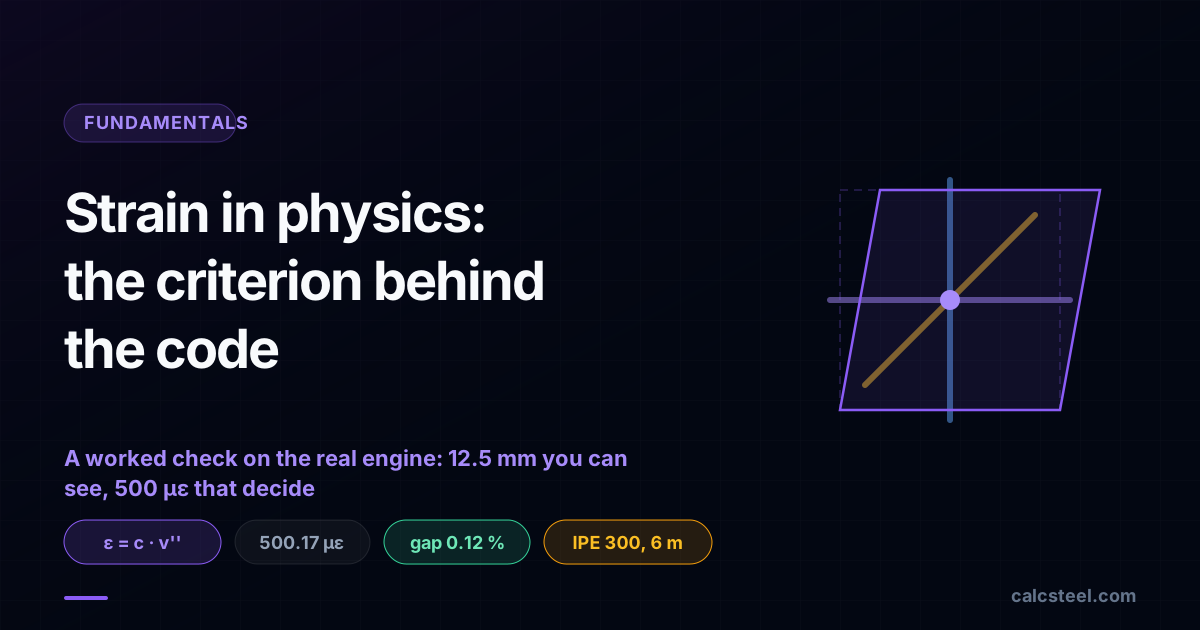
In physics, strain is not movement. It is the gradient of movement: a ratio of lengths, with no unit, defined by geometry alone before any material, any force and any code enters the room. A solver returns displacements and moments, and it never prints a strain. Yet below yield every strength clause you apply is a strain criterion wearing a stress costume. This article defines strain the way mechanics defines it, then recovers it two independent ways from the real CalcSteel engine on an IPE 300, and lands the two routes 0.12 % apart.
Key takeaways
- Strain is a derivative of the displacement field, not a displacement. Move a loaded model 144.55 m across the grid and the engine returns the same forces and the same 499.58 µε, because a translation has no gradient.
- A ratio of lengths has no unit. The whole elastic range of structural steel fits inside 0.18 %, which is why the working unit is the microstrain, 1 µε = 0.000001.
- At a point, strain is a symmetric tensor with six independent components, not one number. Engineering shear strain γ is exactly twice the tensor component ε, and mixing the two is the classic factor-of-two error.
- Worked check on the shipping engine: an IPE 300 at 6 m under 12 kN/m deflects 12.504 mm. Strain from the shape of the beam gives 499.58 µε, strain from the stress gives 500.17 µε, a 0.12 % gap that is pure finite-difference truncation.
- Below yield, σ = Eε is one to one, so checking stress and checking strain are the same act. The deflection clause is the one that is genuinely different: four beams all at δ = L/300 sit anywhere from 533 µε to 1065 µε, set only by depth over span.
The number the solver never prints
Run an IPE 300 over a 6 m simple span under 12 kN/m through the CalcSteel engine and you get two numbers on screen. The mid-span moment is 54.00 kNm. The mid-span deflection is 12.504 mm, which is L/480. Both are useful, both go into a report, and neither is what the steel is actually doing.
What the steel is doing is stretching by 500 parts per million at the bottom flange and shortening by the same amount at the top. That number, 500 µε, is the strain. The solver never printed it. No clause in AISC 360 or EN 1993-1-1 asks you to compare it against anything. And yet it is the quantity the material responds to, the quantity a strain gauge would read if you bonded one on, and the quantity that every yield check is secretly about.
This is a fundamentals article with a worked check attached. It defines strain the way physics defines it, which is stricter and stranger than the definition most engineers carry around, and then it recovers that definition from the shipping FEM engine two independent ways to prove the definition is not decorative.
Strain in physics: a definition with no force in it
Here is the definition, and the thing to notice is what is missing from it. Take a body. Every material point in it moves from where it was to where it now is. Call that displacement field u(x). Normal strain in the x direction is the derivative of that field:
εx = ∂ux / ∂x
No force. No stiffness. No material. No safety factor. Strain is a purely kinematic quantity: it describes how a body has changed shape, and it would be defined identically for steel, rubber, water or a galaxy. Force enters later, through a separate statement called a constitutive law, and the whole art of solid mechanics lies in keeping those two statements apart.
The engineering-strain version most people meet first, ε = ΔL/L, is this same definition with the derivative replaced by a finite ratio, valid when the stretch is uniform along the length. It is the definition in a special case, not a different definition.
What the derivative buys you is precision about a question the ratio cannot even ask: what happens when the whole body moves?
The rigid-body test, run on the real engine
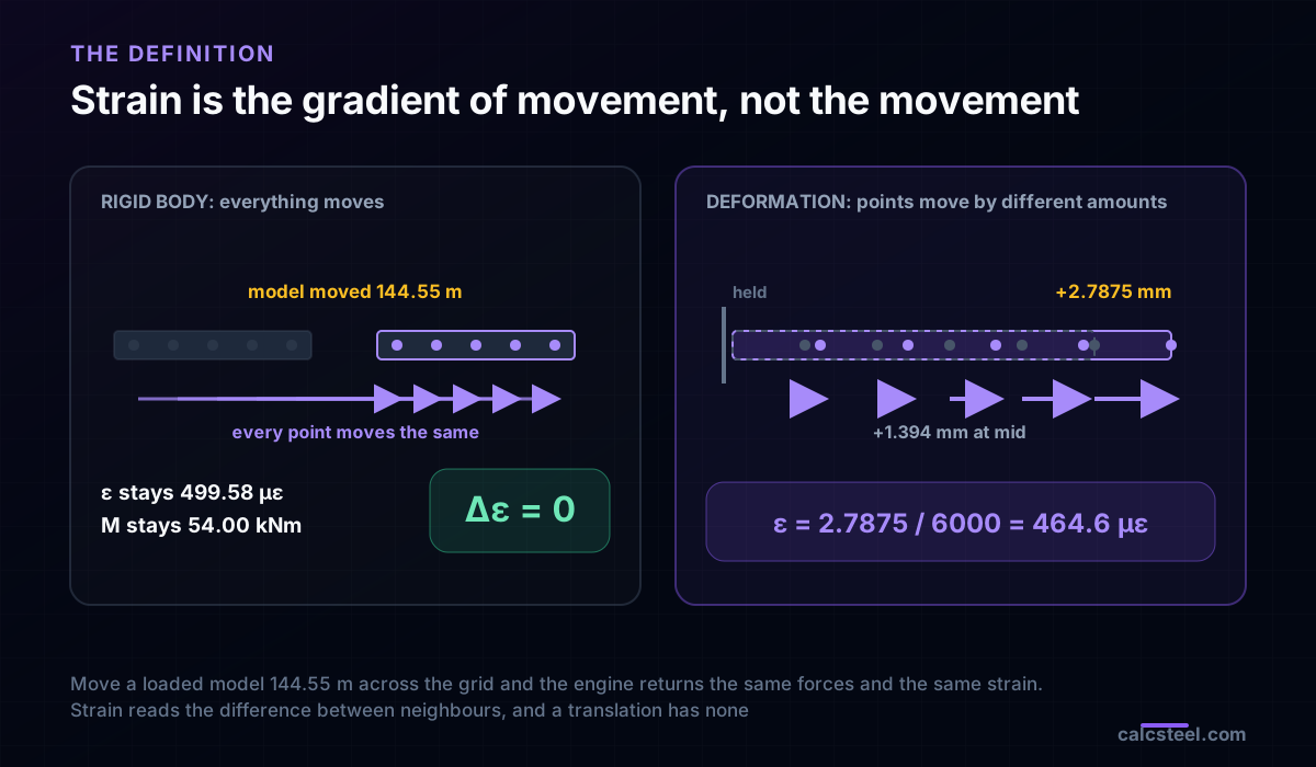
If strain is a derivative of displacement, then a displacement field that is the same everywhere must produce exactly zero strain. Differentiate a constant and you get nothing. Physically: pick up a loaded beam and carry it across the room, and you have not stressed it further by one pascal.
That sounds obvious in words and is easy to get wrong in code, so it is worth testing on the thing that actually does your calculations. We took the same IPE 300 model, translated every node by 137 m in x, 42 m in y and 19 m in z, a bodily move of 144.55 m, and re-solved.
| Quantity | At the origin | 144.55 m away |
|---|---|---|
| Mid-span deflection | 12.5042 mm | 12.5042 mm |
| Peak moment | 54.00 kNm | 54.00 kNm |
| Extreme-fibre strain | 499.58 µε | 499.58 µε |
| Every element end force | identical to the last decimal the solver reports | |
Every node in that second run has completely different coordinates and completely different absolute displacements. Not one internal force moved. That is the definition doing its job: the engine measures relative motion between neighbouring points, and 144.55 m of common motion contributes none.
The same invariance is why a support settlement does nothing to a statically determinate structure. Drop one end of a simply supported beam by 30 mm and the beam rotates as a rigid body into its new position, with no curvature added anywhere and no moment anywhere. Do the same to a three-support continuous beam and you get real curvature, real strain and real moment, because that structure cannot absorb the movement without bending. The difference is not the size of the movement. It is whether the movement has a gradient.
At a point, strain is six numbers, not one
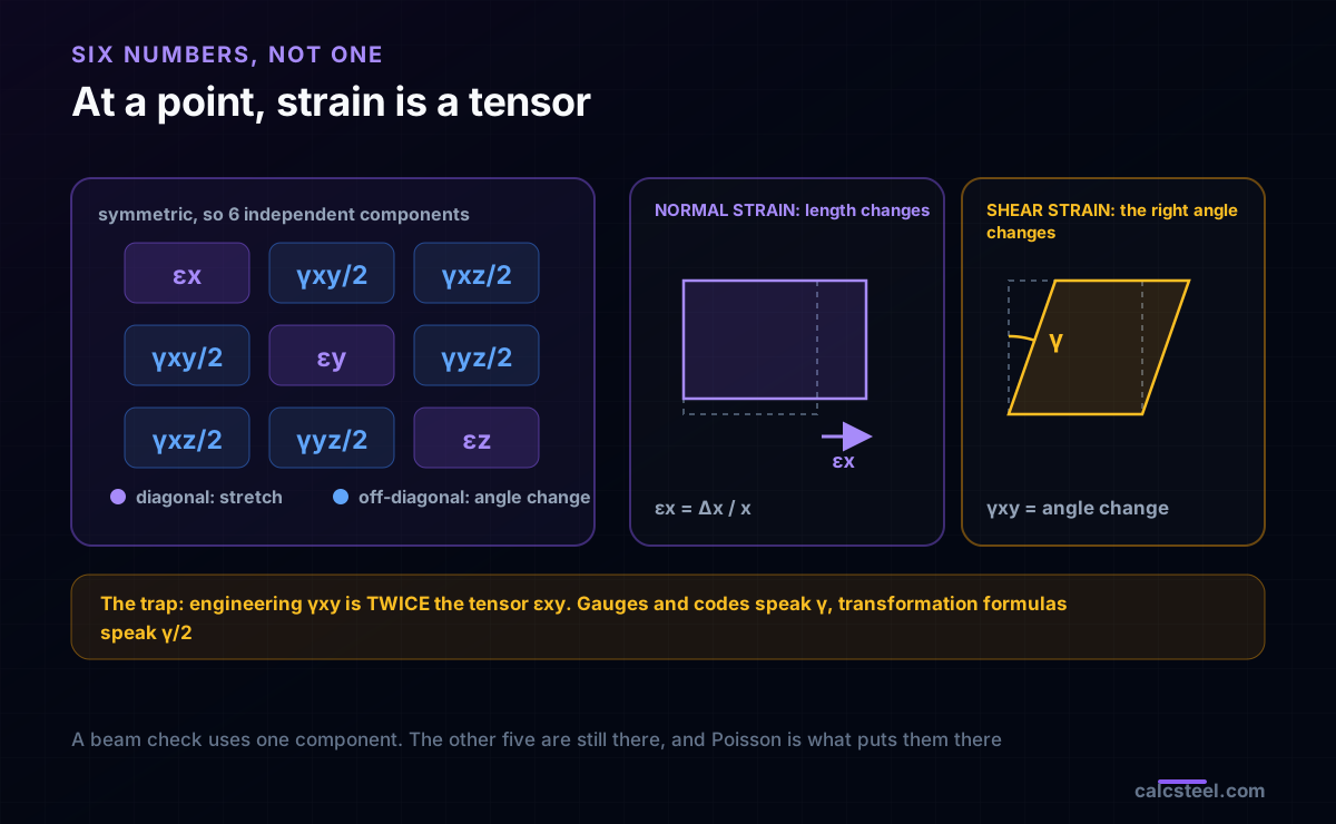
The displacement field has three components and there are three directions to differentiate in, which gives nine derivatives. Split each pair into a symmetric and an antisymmetric part, throw away the antisymmetric part (that is rigid rotation, which we just established is not strain), and what survives is the small-strain tensor:
εij = ½ ( ∂ui/∂xj + ∂uj/∂xi )
It is symmetric, so nine entries collapse to six independent numbers: three normal strains that change lengths, and three shear strains that change angles. A right angle scribed on the surface of a loaded web does not stay a right angle, and the amount by which it opens or closes is the shear strain.
Here is the trap that has cost more marks and more debugging hours than any other item on this page. There are two conventions in circulation:
- Engineering shear strain γxy is the total change in the right angle, in radians. This is what a strain gauge reports, what γ = τ/G returns, and what design standards mean.
- Tensor shear strain εxy is exactly half of it. This is what belongs in the matrix above, and the only version for which the rotation and transformation formulas, including Mohr's circle, are correct.
γ = 2ε. Feed a gauge reading straight into a transformation formula written for the tensor and every principal value you get out is wrong by a factor related to two. It is not a subtle error, but it is a quiet one, because the answer still looks like a strain.
A ratio has no unit, which is why the microstrain exists
Strain is a length divided by a length. Metres over metres, millimetres over millimetres, it cancels. Strain is dimensionless, and any unit you see attached to it is a bookkeeping device rather than a physical unit.
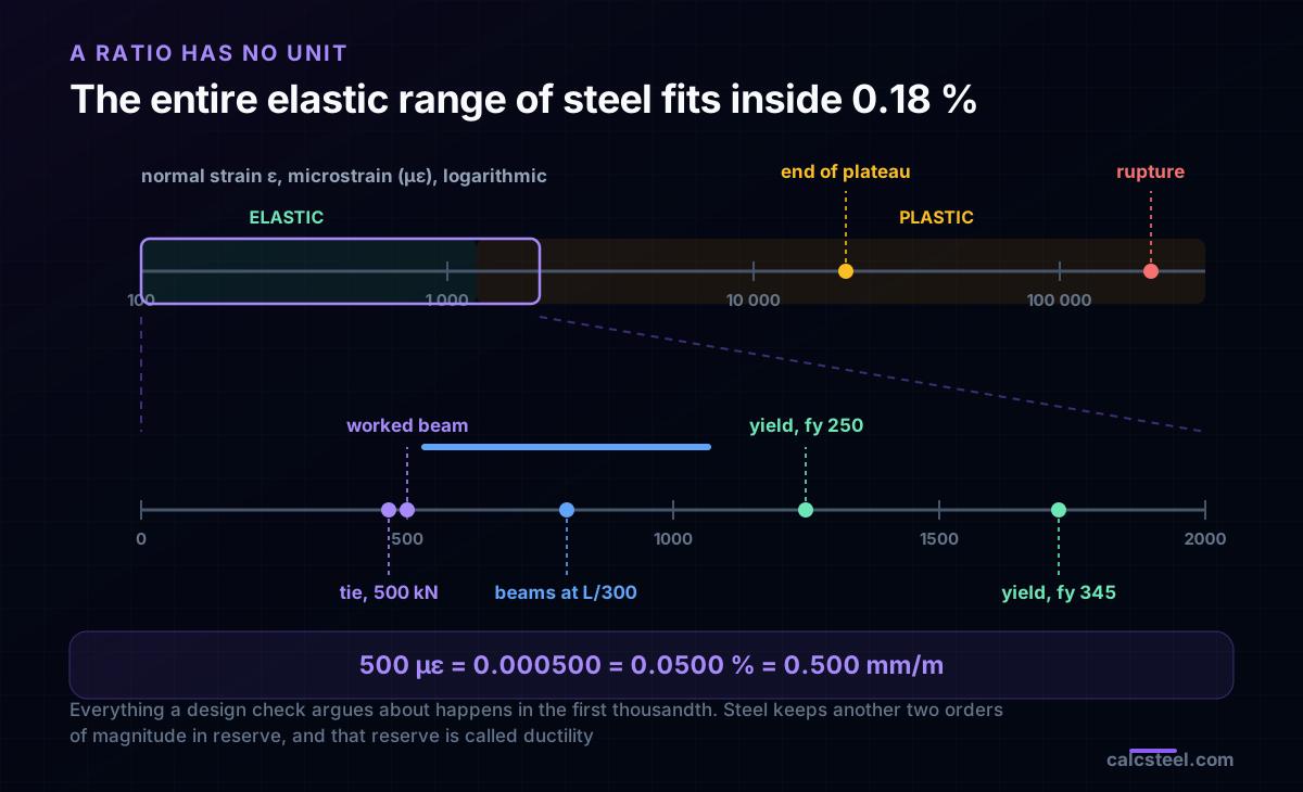
Structural steel strains are inconveniently small, so four notations circulate for the same quantity:
| Notation | The worked beam below | Where you meet it |
|---|---|---|
| Pure ratio | 0.000500 | formulas, solver internals |
| Microstrain, µε | 500 µε | gauges, test reports, FEA output |
| Percent | 0.0500 % | material certificates, elongation at rupture |
| mm/m | 0.500 mm/m | site measurement, camber, fabrication |
The microstrain wins in practice for the same reason the millimetre wins over the metre on a drawing: it puts the working numbers in the range 100 to 2000 where a human can compare them at a glance. One µε is one part per million.
Put the whole range on one axis and the proportions are startling. Yield arrives at 1250 µε for fy = 250 MPa and 1725 µε for fy = 345 MPa. Rupture elongation on a tension coupon is around 20 %, which is 200 000 µε. The entire elastic range, the part every design calculation argues about, is the first 0.18 % of a journey that runs to 20 %. Everything after it is the reserve we call ductility, and it is roughly two orders of magnitude larger than the part we design in.
Where the material finally enters
Nothing so far has mentioned steel. Strain would be defined the same way for a rubber band. The material enters through a second, entirely separate statement: the constitutive law, which says what stress a given strain produces. For steel below yield that statement is Hooke's law.
σ = E · ε
E, Young's modulus, is a measured property. The CalcSteel engine carries E = 200 GPa and G = 76.92 GPa for hot-rolled steel, and those two together fix Poisson's ratio at ν = E/2G − 1 = 0.30.
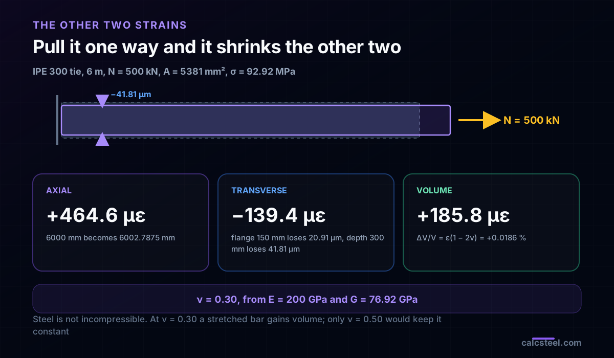
We did not have to take the engine's word for E. Pull an IPE 300 tie, A = 5381 mm², with 500 kN and the engine reports the free end moving 2.7875 mm over a 6000 mm length. That is a strain of 464.6 µε against a stress of 92.92 MPa, and 92.92 / 0.0004646 = 200 000 MPa. Young's modulus recovered from the displacement field, not assumed.
Two things about that constant are worth carrying forward. First, it is identical for every structural grade: A36, A572-50, S355 and MR250 all have the same E. Changing grade moves where yield happens, never how stiff the steel is. Second, the value is a convention as much as a measurement. AISC 360 uses 29 000 ksi, about 199.9 GPa. Eurocode 3 §3.2.6 uses 210 000 MPa. Same steel, a 5 % difference in every strain you compute from a stress, which matters the moment you compare a gauge reading against a calculated value.
Worked check, part 1: the beam, and proving the engine first
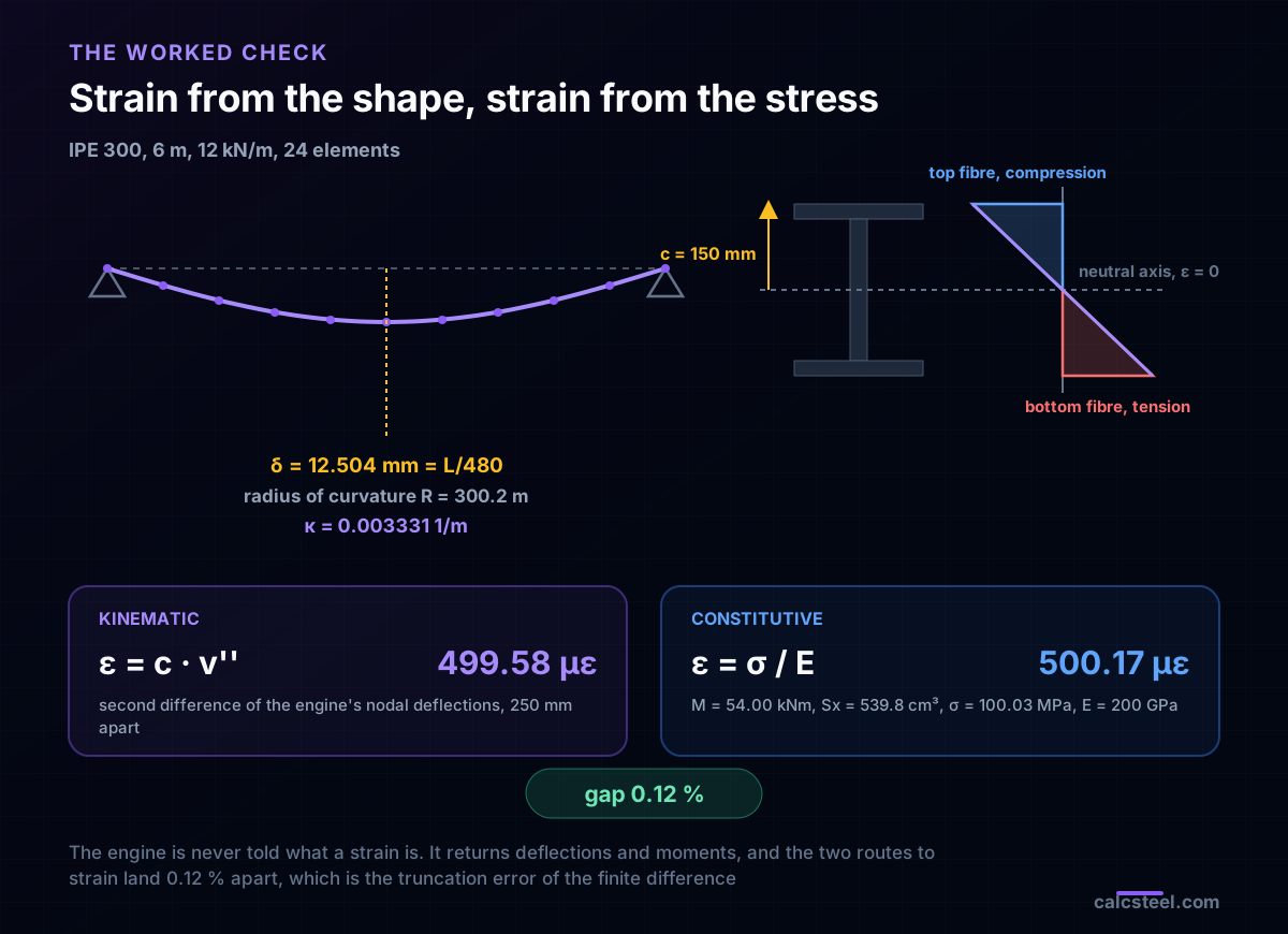
The worked example is deliberately ordinary: an IPE 300 in MR250 steel, fy = 250 MPa, simply supported over 6.00 m, carrying a uniform 12 kN/m. Section depth 300 mm, so c = 150 mm from the neutral axis to the extreme fibre. Ix = 8097 cm⁴ and Sx = Ix/c = 539.8 cm³, both from the shipping catalogue. The model is meshed into 24 elements, giving a node every 250 mm, for reasons that matter in part 2.
Before trusting anything the engine says about strain, it has to reproduce the two closed-form answers everyone knows:
| Quantity | Closed form | Engine | Error |
|---|---|---|---|
| Peak moment, wL²/8 | 54.000 kNm | 54.000 kNm | 0.00 % |
| Mid-span deflection, 5wL⁴/384EI | 12.5042 mm | 12.5042 mm | 0.00 % |
The deflection is L/480, comfortably inside a typical L/300 limit, and the bending stress will turn out to be 100 MPa against a 250 MPa yield. This beam passes everything. That is the point: we are not looking at a failure, we are looking at what a perfectly healthy beam is physically doing.
Worked check, part 2: strain read off the shape of the beam
The first route to strain uses no material property at all. It is pure kinematics, exactly as the definition demands.
Bending a beam bends its axis into a curve. Euler-Bernoulli kinematics says plane sections stay plane and normal to that curve, from which the strain at a distance y from the neutral axis is
ε(y) = −y · κ, where κ = 1/R = v''
κ is the curvature, R the radius of curvature, and v'' the second derivative of the deflected shape. Notice that the only inputs are a shape and a distance. Nothing here knows the beam is steel.
The engine gives us the shape directly: 25 nodal deflections, 250 mm apart. Taking the central second difference of the three deflections around mid-span gives
κ = 0.003331 1/m, that is R = 300.2 m
A 6 m beam bent to a radius of 300 metres. It is worth pausing on that: the sag you would notice, 12.5 mm, comes from an arc so gentle that its radius is fifty times the span. Multiply the curvature by c = 150 mm and the extreme fibre strain is
ε = κ · c = 0.003331 × 0.150 = 499.58 µε
The bottom fibre is in tension at that value, the top fibre in compression at the same magnitude, and the neutral axis is at zero. And the totals are small in a way that is easy to underestimate: integrating the strain along the whole bottom flange, that fibre ends up 2.0 mm longer than it started, while the beam itself dropped 12.5 mm. The visible movement is six times the actual stretch, because most of the deflection is accumulated rotation, not material extension.
Worked check, part 3: strain read off the stress, and the 0.12 % gap
The second route ignores the shape entirely and goes through the material. Take the moment from the element forces, convert to stress with the section modulus, divide by E:
σ = M / Sx = 54.00 kNm / 539.8 cm³ = 100.03 MPa
ε = σ / E = 100.03 / 200 000 = 500.17 µε
Two routes, one from a shape and one from a force, meeting at:
| Route | What it used | Strain |
|---|---|---|
| Kinematic, ε = c·v'' | nodal deflections only | 499.58 µε |
| Constitutive, ε = σ/E | element forces and E | 500.17 µε |
| Gap | 0.12 % |
The gap is not a modelling error and it is not physics. It is arithmetic. A central second difference approximates v'' with a truncation term of h²/12 × v'''', and for this beam with h = 250 mm that term is 0.116 % of the curvature. It is the finite difference, not the engine, that is 0.12 % off. Halve the node spacing and the gap falls by a factor of four.
The agreement is the real result. The engine was asked for deflections and moments and nothing else. The word strain appears nowhere in its output. Yet the shape it returned and the forces it returned carry the same strain, to three digits, because both are consequences of one displacement field. That is what internal consistency in a solver looks like, and it is the check worth running whenever you are unsure whether a model is telling you something real.
See it yourself: read a stress, get a strain
The calculator below is the shipping CalcSteel beam tool. Put your own span, load and section into it and it returns the maximum moment, the maximum deflection with its L/x ratio, and the bending stress σ = M/Sx.
To turn its output into the physics of this article, do one division:
ε [µε] = σ [MPa] / 200 000 × 1 000 000 = σ × 5
At E = 200 GPa the conversion is that clean: five microstrain per megapascal. A stress of 100 MPa is 500 µε. A stress of 160 MPa is 800 µε. Set the span to 6 m and the section to an IPE 300 with 12 kN/m and you should land on the 100.03 MPa and 12.5 mm from the worked check above.
Then try the comparison that makes the last section of this article concrete. Keep loading the beam until the deflection reads L/300, note the stress, multiply by five. Now stretch the span to 9 m and load it back to L/300 again. Same deflection verdict, and a strain that is a third lower.
Max moment
45 kN·m
Max shear
30 kN
Max deflection
10.55 mm
= L/569
Bending stress σ
84.4 MPa
σ = M/Sx
Utilization
44.0%
NBR 8800 · δ ≤ L/250
Geometry & supports
Section
Ix 7999 cm⁴ · Sx 533 cm³ · 42.2 kg/m
Point loads (↓ positive)
None — add as many as you need.
Distributed loads (uniform or trapezoidal)
Model sketch
Diagrams — free PNG / SVG / CSV export, no watermark
Step-by-step — the calculation memory of YOUR beam
IPE 300 · L = 6 m · fy = 250 MPa
1. Reactions (equilibrium of the solved FEM model)
ΣFy = 0 · ΣM = 0
R_A = 30 kN · R_B = 30 kN
2. Peak shear (read from the SFD)
Vmax = |V(x)|max
Vmax = -30 kN @ x = 6 m
3. Peak moment (read from the BMD)
Mmax = |M(x)|max
Mmax = 45 kN·m @ x = 3 m
4. Peak deflection
EI = 15998 kN·m² (E = 200 GPa)
δmax = 10.55 mm @ x = 3 m = L/569
5. Elastic bending stress
σ = Mmax / Sx = 45.00 × 10³ / 533.3
σ = 84.4 MPa
6. Bending check — both codes, side by side
NBR 8800: σ ≤ fy/1.10 = 227.3 MPa · AISC 360: σ ≤ 0.90·fy = 225 MPa
NBR 37.1% PASS · AISC 37.5% PASS
7. Deflection check (serviceability — code-independent)
δ ≤ L/250 = 24 mm
10.55 mm / 24 mm = 44.0% PASS
Recomputed live from the current inputs by the direct-stiffness FEM engine — change any load and every step updates. Reproduce it by hand with the formulas in the sections below.
Lightest catalog profiles that pass (974 flexural candidates · NBR 8800)
| Profile | Std | Weight | Total steel | σ util | δ util | |
|---|---|---|---|---|---|---|
| W310x21 | AISC | 21 kg/m | 126 kg | 83% | 98% | |
| VS 300x23 | BR | 22.6 kg/m | 136 kg | 71% | 84% | |
| U 300x90x6.3 | BR | 23.1 kg/m | 139 kg | 82% | 98% | |
| U 300x100x6.3 | BR | 24.1 kg/m | 145 kg | 77% | 91% | |
| VS 250x25 | BR | 24.6 kg/m | 148 kg | 70% | 100% |
Elastic bending (σ = M/Sx vs fy/γa1, γa1 = 1.10 — NBR 8800) + deflection screening of the full flexural catalog. Lateral-torsional buckling, shear and local buckling are NOT checked here — run the full NBR 8800 / AISC 360 verification in the 3D editor.
The two strains you did not ask for
Pull a bar along one axis and it does not only get longer. It gets thinner. That coupling is Poisson's ratio, and it is why strain at a point is a tensor even when the loading is as one-dimensional as loading gets.
Back to the 500 kN tie. The axial strain was 464.6 µε. The two transverse strains are each
εt = −ν · εa = −0.30 × 464.6 = −139.4 µε
On an IPE 300 that means the 150 mm flange gets 20.91 µm narrower and the 300 mm depth loses 41.81 µm, while the member gains 2.7875 mm of length. Nobody will ever measure those two numbers on site, and they are still real, and they are why a wide plate in tension behaves differently at its centre than at its free edges.
Add the three together and you get the volumetric strain:
ΔV/V = εx + εy + εz = εa(1 − 2ν) = 464.6 × 0.40 = +185.8 µε
The bar gains 0.0186 % in volume. Steel is not incompressible. Only a material with ν = 0.50, like rubber near its limit, keeps its volume constant when you stretch it, and the fact that steel does not is precisely why hydrostatic pressure alone will not yield it. That observation is the seed of the von Mises criterion, which throws away the volumetric part of the strain and judges failure on the distortional part alone.
Why every strength clause is a strain criterion in disguise
Open any steel standard and you will not find a strain limit for ordinary member design. AISC 360 and NBR 8800 compare stresses and forces. EN 1993-1-1 compares design effects against design resistances. Strain is not in the inequality.
It does not have to be, because below yield σ = Eε is a one-to-one map with a single constant in it. Divide both sides of a stress check by E and you have a strain check with identical content:
σ ≤ fy ⟺ ε ≤ fy/E = εy
Our beam at 500 µε against fy = 250 MPa, which is εy = 1250 µε, is at 40.0 % of yield strain and at 40.0 % of yield stress. The same fraction, necessarily. Codes chose stress because it is what a testing machine reports and what a resistance formula naturally produces, not because stress is the more fundamental quantity. Physically, strain is upstream: the material deforms, and the stress is its response.
The disguise slips the moment the map stops being one to one, which is exactly at yield. Past that point one stress corresponds to a whole plateau of strains, and standards that need to talk about behaviour beyond yield are forced back into strain language:
- Section classification. EN 1993-1-1 Class 1 to 4 is a statement about how much rotation, meaning how much strain, a cross-section can deliver before it buckles locally. Class 1 sections are the ones allowed to reach large plastic strains.
- Plastic design. A plastic hinge is a region asked to strain far past εy while its moment stays at Mp. Only strain can describe what is happening there.
- Seismic detailing. Ductility ratios, rotation demands and the AISC 341 requirements are strain demands with different names.
- Elongation on the mill certificate. The percentage on the material certificate is a strain, and it is the only strain most engineers ever read off a document.
Same deflection limit, twice the strain
There is one clause that is genuinely not a strain criterion, and it is the one people most often assume is a proxy for one: the deflection limit.
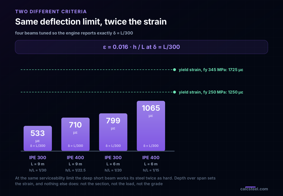
We tuned four beams so the engine reports exactly δ = L/300, then read the strain at mid-span from each:
| Beam | h/L | Load | δ | σ | ε | Fraction of εy at fy = 250 |
|---|---|---|---|---|---|---|
| IPE 300, 9 m | 1/30 | 5.687 kN/m | 30.0 mm | 106.7 MPa | 533 µε | 42.6 % |
| IPE 400, 9 m | 1/22.5 | 15.608 kN/m | 30.0 mm | 142.2 MPa | 710 µε | 56.8 % |
| IPE 300, 6 m | 1/20 | 19.193 kN/m | 20.0 mm | 160.0 MPa | 799 µε | 63.9 % |
| IPE 400, 6 m | 1/15 | 52.675 kN/m | 20.0 mm | 213.3 MPa | 1065 µε | 85.2 % |
All four are equally acceptable to the serviceability clause. One of them is working its steel twice as hard as another. The loads differ by a factor of nine and the strains do not follow them, which is the tell that something simpler is in charge.
It is. Set 5wL⁴/384EI = L/k, substitute into ε = Mc/EI, and the load, the modulus and the second moment of area all cancel:
ε = 48c / (5kL) = 9.6 c / (kL), so at k = 300, ε = 0.016 · h/L
Strain at the deflection limit depends on the depth-to-span ratio and on nothing else. Not the section, not the load, not the grade. The engine agrees with that formula to better than 0.12 % on all four beams, which is the same finite-difference truncation as before.
The practical consequences are worth stating plainly. A deep, short beam taken to L/300 sits at 85 % of yield strain for fy = 250 steel and will be governed by strength long before serviceability. A shallow, long-span beam taken to the same L/300 sits at 43 % and is squarely serviceability-governed. If you have ever wondered why deflection sizes some of your beams and stress sizes others, this single ratio is most of the answer. And it is why upgrading the grade rescues the first beam and does nothing at all for the second: a higher fy moves εy, and the deflection criterion never looked at εy.
Seven ways this goes wrong in practice
- Treating a displacement as a strain. A 30 mm deflection tells you almost nothing about how hard the material is working until you know the span and the depth. Our 9 m beam moves 50 % further than the 6 m one and strains 33 % less.
- The factor of two on shear. γ = 2ε. Gauges and codes report γ; the tensor and every transformation formula want ε. Mixing them silently halves or doubles the answer.
- Using the wrong E for the conversion. 200 GPa, 210 GPa and 29 000 ksi are all in daily use. A strain computed from a stress inherits a 5 % spread from that choice alone, which is more than most people's tolerance when they compare a gauge against a model.
- Assuming a stronger steel strains less. Grade does not change E. An A572-50 beam and an A36 beam of the same section under the same load deflect identically and strain identically. Only the distance to yield changes.
- Forgetting that linear strain does not tolerate large rotation. The small-strain tensor discards rotation to first order, which is correct only while rotations stay small. Push a slender member into large-displacement territory and the linear measure reports strain that is not there. That is the moment to switch to a geometrically nonlinear analysis.
- Confusing engineering and true strain in the wrong regime. At 500 µε they differ by 0.025 % and nobody cares. At 20 % elongation they differ by about 9 % and the distinction decides whether a number means anything.
- Reading a strain field that no displacement field could produce. Strain components are not independent: they are six derivatives of three functions, and they must satisfy the compatibility conditions. In two dimensions that is ∂²εx/∂y² + ∂²εy/∂x² = ∂²γxy/∂x∂y. Interpolated or hand-assembled strain fields that violate it correspond to a body that has torn itself apart.
Sources
- 1.AISC 360-16, Specification for Structural Steel Buildings (E = 29,000 ksi; elastic section modulus and flexural stress)
- 2.Eurocode 3 (EN 1993-1-1) §3.2.6 material constants E, G and ν, and §5.5 cross-section classification
- 3.ABNT NBR 8800, Projeto de estruturas de aço e de estruturas mistas de aço e concreto
- 4.Gere and Goodno, Mechanics of Materials (normal and shear strain, Poisson's ratio, volumetric strain, curvature of a beam)
- 5.Timoshenko and Goodier, Theory of Elasticity (the small-strain tensor and the compatibility conditions)
- 6.Hibbeler, Mechanics of Materials (engineering strain, strain transformation and the Euler-Bernoulli kinematic assumption)
- 7.ASTM A370 / ASTM E8, Standard Test Methods for Tension Testing of Metallic Materials (elongation at rupture)
Try CalcSteel for free
Model, analyze and design steel structures in your browser. No install, no signup.
Open the 3D editor