Strain in Engineering: the Ductility Criterion Behind the Code, With a Worked Check
In physics, strain is a definition. In engineering it is a permission. Every clause that lets you build something cheaper, banking the plastic modulus instead of the elastic one, redistributing a support moment, calling a section compact, is sold to you in exchange for strain the steel has to supply. The code writes the permission in stress and never prints the price. This article puts the ledger back on the table: the same IPE 400 carries 30.0 % more load, and the CalcSteel engine plus a fibre integration of the real section says that costs the support flange 1.409 % strain against the 2.662 % the material clause guarantees.
Key takeaways
- The economy is real and it is large. The same two-span IPE 400 in S355 goes from 49.31 kN/m under a pure elastic check to 64.12 kN/m using the plastic modulus and the redistribution EN 1993-1-1 allows. That is +30.0 % of load out of the same steel.
- Everything you spend is denominated in one unit: the yield strain, εy = fy/E, which is 1 775 µε for S355. Banking Wpl costs about 2.9 εy at the support. Cashing the redistribution on top of it costs 7.9 εy.
- The supply side is a material clause, not a strength clause. EN 1993-1-1 §3.2.2 asks for fu/fy ≥ 1.10, elongation ≥ 15 % and εu ≥ 15 εy. Fifteen against a demand of 7.9 leaves a margin of 1.89, and the ledger closes.
- The clause almost everyone quotes wrong: §5.4.1(4)B lets the elastic peak exceed Mpl by 15 %, which is a 13.04 % cut off that peak, not a 15 % one. AISC 360 sells the same permission at a flat 10 %.
- Run the same balance with an ideal elastic-perfectly-plastic steel and it fails: the hinge would have to reach 32.5 εy, which is 5.76 % strain, against a supply of 15. The hardening that §3.2.2 guarantees is not decoration, it is what pays the bill.
- The demand in multiples of εy is identical for S235, A992, S355 and S460. That is exactly why the clause is written as a ratio, εu ≥ 15 εy, and not as a strain.
- Strength is not the last word. At 64.12 kN/m the same beam deflects 31.96 mm, which is L/250 against a floor limit of L/300. The strain was available, the serviceability clause took the permission back.
The 30 % you are allowed to have, and never priced
Take a two-span continuous beam, an IPE 400 in S355 over two 8 m bays, carrying a uniform load. Check it the strictest way anyone still checks anything: elastic analysis, elastic section modulus, stress at the extreme fibre must not exceed fy. It carries 49.31 kN/m.
Now check the same beam the way the code actually allows. Use the plastic modulus, because the section is compact. Redistribute the support moment, because the section can form a hinge and rotate. Same steel, same profile, same span, same supports, nothing welded on, nothing stiffened. It carries 64.12 kN/m. That is 30.0 % more load, and it is free in the sense that no one sends you an invoice for it.
Except that something does pay. The extra 30 % is bought with strain: the steel at the support has to stretch further than a first-yield check ever contemplates, and hold together while it does. The code never prints that number. It writes the permission in stress, in section modulus, in a percentage of moment, and the strain it is quietly spending stays off the page.
This article puts it back on the page. We run the real CalcSteel engine on the beam, integrate the real section fibre by fibre, and price each permission in the only currency that makes them comparable: multiples of the yield strain. Then we look up what the material clause actually guarantees and see whether the ledger closes.
Strain is the currency, and εy is the unit
Strain is a ratio of lengths: how much a fibre stretched, over how long it was. It has no unit, which is why it is usually quoted in microstrain, 1 µε = 0.000001, or in per cent.
The number that turns it into a currency is the yield strain:
εy = fy / E
For S355 with E = 200 GPa, that is 355/200000 = 0.001775, or 1 775 µε, or 0.1775 %. For S235 it is 1 175 µε. For S460 it is 2 300 µε. The engine agrees: pull a 6 m IPE 400 tie with 800 kN and it elongates 2.8415 mm, which is 473.6 µε, which back-solves to E = 200 000 MPa exactly. Every constitutive constant below is measured off the solver, not assumed.
From here on, every price is quoted as μ = ε/εy, the ductility ratio. μ = 1 is first yield. μ = 15 is the number to remember, and the next section explains why.
What the steel guarantees: three numbers in §3.2.2
Most engineers can recite the strength clauses of EN 1993-1-1 and have never read §3.2.2, which is a shame, because it is the one that makes the others legal. It is a ductility requirement, and it has three parts:
- fu / fy ≥ 1.10. The steel must get stronger after it yields, by at least 10 %.
- Elongation at failure ≥ 15 % on a gauge length of 5.65√A₀.
- εu ≥ 15 εy. The strain at ultimate tensile strength must be at least fifteen times the yield strain.
That third line is the supply side of the whole ledger. It is deliberately written as a ratio and not as a strain, and section 11 shows the reason: the demand is also a ratio, so a clause written this way covers every grade at once. For S355 it means the steel promises 15 × 1 775 = 26 625 µε, which is 2.662 % strain, before it reaches its tensile peak.
AISC 360 does not spell this out the same way, because it does not have to: ASTM A992 carries a maximum yield-to-tensile ratio of 0.85 and a minimum elongation, which is the same guarantee written from the other end.
So: the steel offers 15 εy. The rest of this article is about what the code spends out of that account.
Before the argument: proving the engine on a beam we can solve by hand
Nothing below is worth reading if the solver is wrong, so it gets calibrated first against a case with an exact closed form. Two spans of 8 m, IPE 400, a plain 30 kN/m on both, 32 elements per span:
| Quantity | Engine | Closed form | Error |
|---|---|---|---|
| Support moment, wL²/8 | 240.000 kNm | 240.000 kNm | 0.0000 % |
| Peak span moment, 9wL²/128 | 135.000 kNm | 135.000 kNm | 0.0000 % |
| Its position, 3L/8 | 3.000 m | 3.000 m | exact |
| Span / support ratio, 9/16 | 0.5625 | 0.5625 | exact |
| Deflection, wL⁴/185EI | 14.9519 mm | 14.9447 mm | 0.048 % |
The moments are exact because a cubic element reproduces a parabolic moment field with no discretisation error at all. The 0.048 % on deflection is the closed form's own rounding, since wL⁴/185EI is itself an approximation of wL⁴/(184.6 EI). Calibration passes, and the same model is used for everything that follows.
Route 0: the elastic check, and the one fibre nobody sees
The elastic route is the one everybody learns. Take the elastic section modulus, set the extreme-fibre stress to fy, and that is your capacity.
Integrating the real IPE 400 fibre by fibre, with the same root-fillet contribution the CalcSteel profile registry uses, gives Wel = 1 111.1 cm³ and therefore Mel = 355 × 1 111.1 = 394.45 kNm. Set the support moment wL²/8 to that and the beam carries 49.31 kN/m.
What is the strain at that load? Exactly εy, at exactly one fibre, in exactly one cross-section: the top of the flange over the middle support. Two millimetres below it, the steel is still elastic with room to spare. Ninety-nine point something per cent of the beam is idle. That is the cost of the elastic route: μ = 1.0, and it buys nothing beyond a very tidy conscience.
One reconciliation note before the numbers pile up. The section properties here are integrated from the rolled geometry, not read from a table, and the published EN table for an IPE 400 gives Wel = 1 156 cm³ and Wpl = 1 307 cm³ because it models the root fillets more fully. Table values are about 4 % higher, so every absolute kNm and kN/m in this article is about 4 % conservative against a handbook check. Not one ratio changes, and the ratios are the entire argument.
Route 1: the plastic modulus, +13.1 % for about 2.9 εy
The first permission is the cheapest. Once the extreme fibre yields, the section does not fail: the yielded zone spreads inward while the elastic core shrinks, and the moment keeps climbing to a ceiling of fy·Wpl. The ratio of the two ceilings is the shape factor:
α = Wpl / Wel = 1 256.4 / 1 111.1 = 1.1308
Published tables for an IPE 400 give 1 307/1 156 = 1.1306. Two parts in ten thousand, on a quantity computed by two entirely different routes. Mpl = 446.03 kNm, and the beam now carries 55.75 kN/m, +13.1 % over the elastic route.
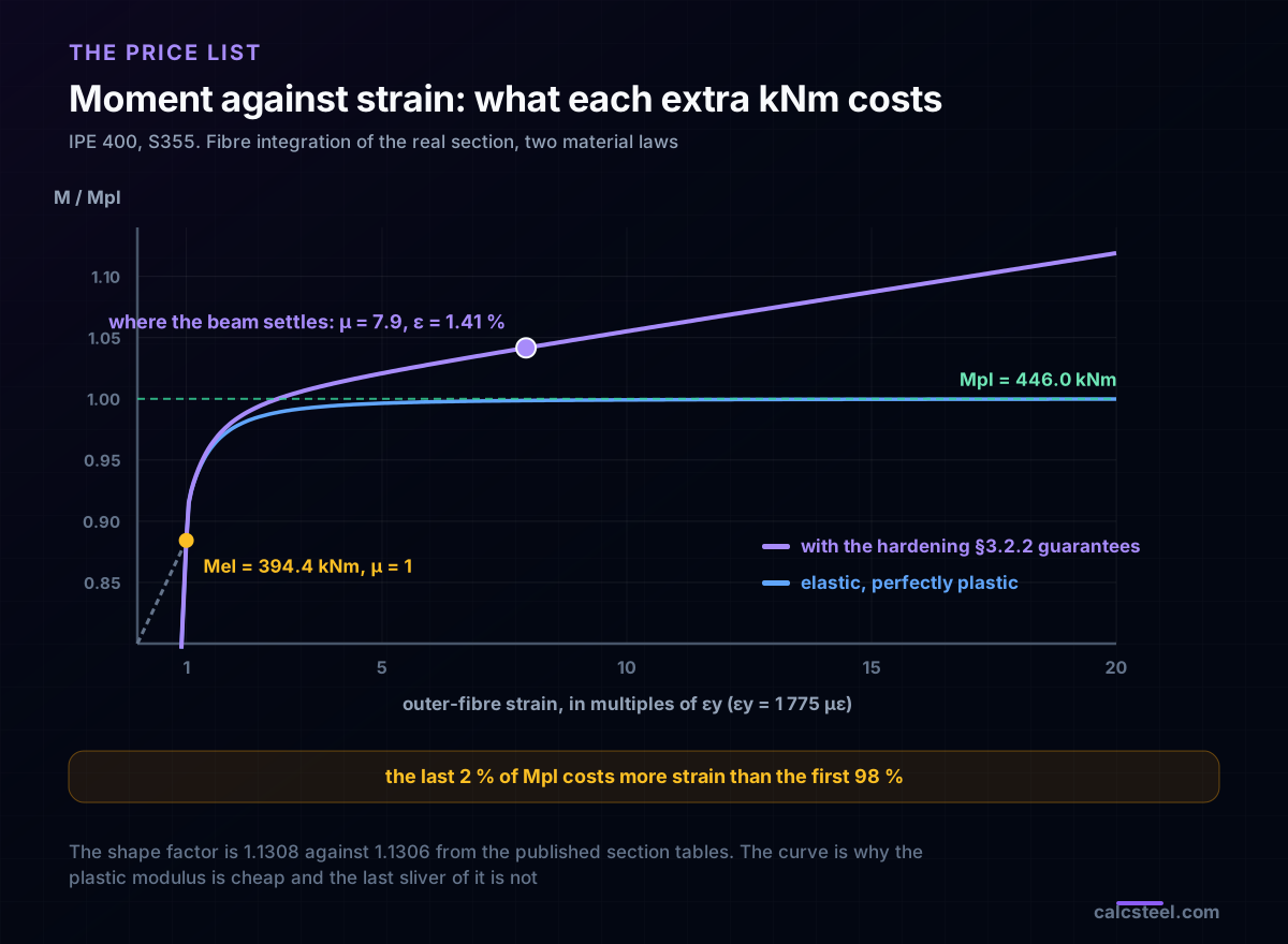
Here is where the price list starts to bite. The moment-curvature curve of the real section is not a corner, it is a knee that flattens out asymptotically. With an ideal elastic-perfectly-plastic steel you reach 98 % of Mpl at μ = 2.14, 99.5 % at μ = 4.27 and 99.9 % only at μ = 9.55. You never actually reach Mpl: the last sliver of it lives at infinite curvature.
Real steel is kinder, because it hardens. With the minimum hardening §3.2.2 guarantees, the section delivers a genuine Mpl at μ = 2.871, which is 5 096 µε, about 0.51 % strain. That is the honest price of the plastic modulus: call it 2.9 εy, against a supply of 15.
Route 2: redistribution, and the clause everyone quotes wrong
The second permission is the one that pays. In a continuous beam the support moment is the peak and the span moment is only 9/16 of it, so the support governs while the span sits at 56 % utilisation. Redistribution moves the problem: let the support yield and shed moment, and the span picks it up until both are working.
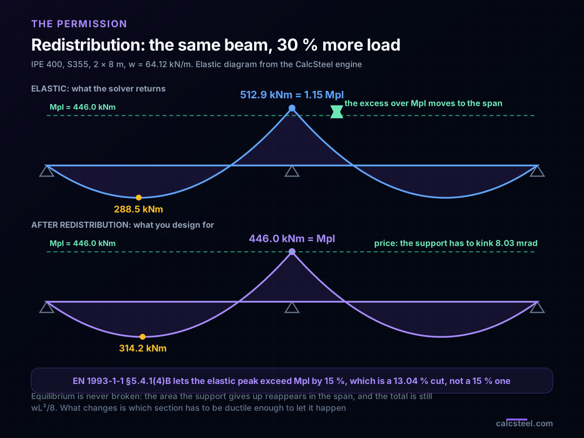
Now the clause. EN 1993-1-1 §5.4.1(4)B is almost universally quoted as permitting a 15 % redistribution. Read the actual wording and it says something subtly different: for Class 1 or Class 2 sections in a continuous beam, elastic global analysis may be used where some peak moments exceed the plastic bending resistance by 15 % maximum, provided the internal forces stay in equilibrium and adequate rotation capacity is available.
That is an excess, not a cut. If the elastic peak may be 1.15 Mpl, then the amount you take off that peak is 1 − 1/1.15 = 13.04 %, not 15 %. Getting this backwards is worth about 2 % of load, always in the unconservative direction.
AISC 360 sells the same permission more simply: a flat 10 % reduction of negative moments at supports for compact, laterally braced, indeterminate members under gravity load, with the positive moments increased to keep equilibrium. It was §B3.7 in AISC 360-10 and in 360-16, and the paragraph moved to Appendix 8 in AISC 360-22.
Priced on the same beam, with the engine confirming the elastic distribution at every load level:
| Route | w | Support design M | Span design M | Gain |
|---|---|---|---|---|
| Elastic, σ ≤ fy | 49.31 kN/m | 394.4 kNm | 221.9 kNm | baseline |
| Plastic modulus, no cut | 55.75 kN/m | 446.0 kNm | 250.9 kNm | +13.1 % |
| Plastic + 10 % cut (AISC 360) | 61.95 kN/m | 446.0 kNm | 297.7 kNm | +25.6 % |
| Plastic + 15 % excess (EN 1993-1-1) | 64.12 kN/m | 446.0 kNm | 314.2 kNm | +30.0 % |
At the last line the elastic peak the solver returns is 512.9 kNm, exactly 1.15 Mpl, and the span moment has climbed from 56 % to 70 % utilisation. Equilibrium was never broken: the area the support gave up reappeared in the span, and the sum is still wL²/8. What changed is which cross-section now has to be ductile enough to allow it.
The invoice: 8.03 mrad at the support
A redistributed moment diagram is not a free choice of numbers that add up. It is a statement that the support has hinged and rotated, and the rotation is computable. Split the continuous beam into two simply supported spans and superpose:
θ = wL³/12EI − 2·MB·L/3EI
Both flexibility terms come from the engine, not from a table. The end rotation of a single 8 m span under 64.12 kN/m measures 30.7773 mrad against a closed form of 30.7773. The end rotation of the same span under a pure end moment measures 3.6000 mrad against 3.6000, applied through a real 1 m overhang with a 60 kN tip force, because the solver takes no nodal moments and faking one is how this check usually goes wrong.
Two sanity checks before using the result. Feed the elastic support moment into the same expression and the required kink is −0.000047 mrad, which is zero to seven digits: the elastic diagram is by definition the one that needs no hinge. Feed the design value of 446.1 kNm and the required kink is 8.0288 mrad from the engine, against 8.0289 mrad closed form.
That is the invoice. To use the 30 % the code offers, the section over the support has to turn through 8.03 mrad while holding its plastic moment. Whether it can is not a moment question any more, it is a strain question.
An ideal steel cannot pay this bill
Now solve the beam properly, with compatibility instead of an assumption. The plastic rotation a section can supply is the excess of its real curvature over the elastic one, integrated along the length where the moment is above Mel:
θsupply = ∫ [ κ(M(x)) − M(x)/EI ] dx
No assumed hinge length, no assumed triangular shape. The moment diagram is the engine's own, on a fine mesh with a node every 25 mm, and κ(M) is inverted from the fibre integration of the real section. Then bisect on the support moment until supply equals demand.
With an ideal elastic-perfectly-plastic steel, the beam settles at a support moment of 446.0 kNm, which is 0.99991 Mpl and a 13.06 % redistribution, almost exactly the code's 13.04 %. So far so good. The price is not:
- peak curvature ductility μ = 32.47
- outer-fibre strain 57 633 µε, which is 5.763 %
- spread over a yielded zone 350 mm long, 0.88 times the section depth
Against a supply of 15 εy, the margin is 0.46. The ledger does not close. Taken literally, an ideal-plastic steel could not legally cash the permission its own code grants.
The reason is the flat top of the ideal curve. To squeeze the last 0.01 % of Mpl out of a section that has no hardening, the curvature has to run away. All of that curvature is charged to the extreme fibre, and the bill is 5.8 % strain.
The line in §3.2.2 that saves the whole scheme
Real steel does not have a flat top, and the clause that guarantees the supply also guarantees the fix. Take §3.2.2 at its literal minimum: a straight line from (εy, fy) to (15 εy, 1.10 fy). That is a hardening slope of
Esh = 0.10 fy / (14 εy) = E/140 = 1 428.6 MPa
Nothing here is invented or fitted. It is the weakest steel the clause admits. Re-run the identical compatibility solution with that one change:
| Ideal, no hardening | Minimum §3.2.2 hardening | |
|---|---|---|
| Support moment reached | 446.0 kNm = 1.000 Mpl | 464.6 kNm = 1.042 Mpl |
| Redistribution actually needed | 13.06 % | 9.43 % |
| Peak ductility μ | 32.47 | 7.94 |
| Outer-fibre strain | 5.763 % | 1.409 % |
| Length of the yielded zone | 350 mm | 450 mm |
| Margin against 15 εy | 0.46, fails | 1.89, passes |
Ten per cent of hardening cuts the strain demand by a factor of four. Two mechanisms do it, and both are worth carrying around:
- The curve stops being flat. A hardening section reaches Mpl at μ = 2.87 and keeps climbing, so the moment it has to deliver is no longer at an asymptote it can only approach.
- The hinge spreads. Because the section keeps gaining strength, the yielded zone grows from 350 mm to 450 mm, and a longer zone delivers the same 8.03 mrad at a lower curvature everywhere in it.
There is a design consequence hiding in the second row. The real beam wants to keep 464.6 kNm at the support, not 446.0, because it hardens instead of capping out. Designing the support for Mpl is therefore conservative on the support and slightly unconservative on the span, which is why the codes bound the redistribution rather than letting you claim any amount you like.
The ledger closes with 1.89 to spare, in every grade
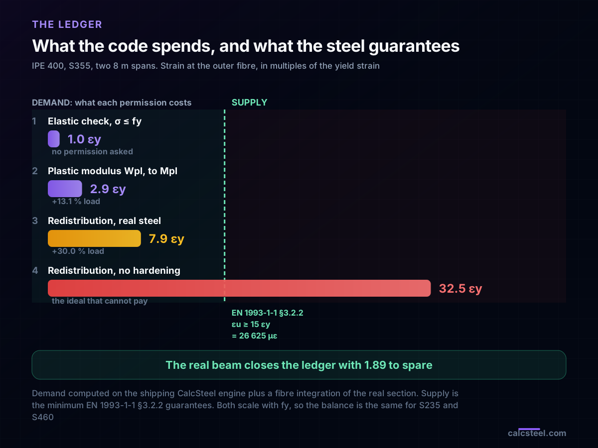
Put the four permissions on one axis, in the currency they are all denominated in:
| What you are buying | Costs | Buys |
|---|---|---|
| Elastic check, σ ≤ fy | 1.0 εy | 49.31 kN/m |
| Plastic modulus, up to a real Mpl | 2.9 εy | 55.75 kN/m, +13.1 % |
| Full redistribution, real steel | 7.9 εy | 64.12 kN/m, +30.0 % |
| The same, with an ideal steel | 32.5 εy | nothing, it is not payable |
| Supply, EN 1993-1-1 §3.2.2 | 15 εy | 2.662 % on S355 |
Now the part that explains the shape of the clause. Run the whole balance again in four grades:
| Grade | εy | w | Demand μ | Demand ε | Supply 15 εy | Margin |
|---|---|---|---|---|---|---|
| S235 | 1 175 µε | 42.44 kN/m | 7.94 | 0.933 % | 1.762 % | 1.89 |
| A992 / Gr. 50 | 1 725 µε | 62.31 kN/m | 7.94 | 1.369 % | 2.587 % | 1.89 |
| S355 | 1 775 µε | 64.12 kN/m | 7.94 | 1.409 % | 2.662 % | 1.89 |
| S460 | 2 300 µε | 83.08 kN/m | 7.94 | 1.826 % | 3.450 % | 1.89 |
The strain demand in per cent nearly doubles from S235 to S460. The demand in multiples of εy does not move at all: 7.94 across the board, a spread under 0.5 %. That is not a coincidence, it is the structure of the problem. Both the demand and the supply scale with fy/E, so their ratio is a pure number. A clause written as εu ≥ 15 εy covers every grade with one line, and a clause written as a strain limit would have needed a different number for each.
The margin is 1.89 in every row. Comfortable, and not so comfortable that the clause was unnecessary.
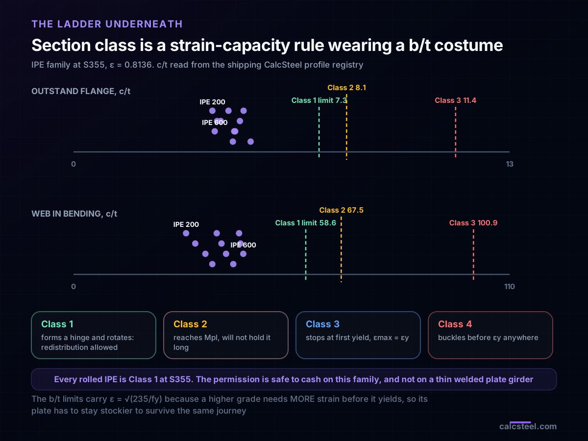
Section class is the fine print on the permission
Everything above assumes the flange and the web can actually reach those strains without folding up first. That assumption has a name, and it is section classification. Class is presented as a table of b/t limits, which makes it look like a geometry rule. It is a strain-capacity rule:
- Class 1: forms a plastic hinge and holds it through the rotation. This is the only class allowed to cash the redistribution.
- Class 2: reaches Mpl but will not hold it long enough to rotate. Plastic modulus yes, redistribution no.
- Class 3: stops at first yield. εmax = εy, and the whole argument of this article is unavailable.
- Class 4: buckles locally before yielding anywhere. Even the elastic modulus has to be reduced.
The tell is the ε in the limits: EN 1993-1-1 Table 5.2 writes them as 9ε, 10ε, 14ε for an outstand flange and 72ε, 83ε, 124ε for a web in bending, with ε = √(235/fy). A higher grade needs more strain before it yields, so its plate has to stay stockier to survive the same journey. Geometry limits that depend on the yield strength are not geometry limits.
For S355, ε = 0.8136, so the Class 1 limits are c/t ≤ 7.32 for the flange and c/t ≤ 58.58 for the web. Reading c/t straight out of the shipping profile registry, the whole IPE family from 200 to 600 comes out Class 1: flanges between 4.14 and 5.28, webs between 28.39 and 42.83. Every one of them has room to spare, by a factor between 1.4 and 1.8 on the flange.
Which is the real lesson. The permission is safe to cash on a rolled I section, and it is exactly the kind of permission you must not carry over to a slender welded plate girder, where a web at c/t = 90 is Class 3 and the whole ledger above is void.
Try it on the same beam
The quickest way to feel the size of the permission is to run both routes yourself. The calculator below solves a beam and gives you the moment and the deflection.
- Set an 8 m span with an IPE 400 and 49.31 kN/m. The moment you get is the elastic capacity, 394 kNm on a support, and this is the beam a first-yield check hands you.
- Now put in 64.12 kN/m, the load the redistributed design allows. Compare the moments, then compare the deflections. The strength went up 30 %, and something else went up with it.
- Change the profile to an IPE 450 and watch how much of the argument you can buy back with 8 kg/m of extra steel instead of with ductility.
Two things the calculator cannot do for you, and no calculator can: confirm that the section is Class 1 at your grade, and confirm that the hinge region is braced against lateral torsional buckling. Both are prerequisites, not afterthoughts.
Max moment
45 kN·m
Max shear
30 kN
Max deflection
10.55 mm
= L/569
Bending stress σ
84.4 MPa
σ = M/Sx
Utilization
44.0%
NBR 8800 · δ ≤ L/250
Geometry & supports
Section
Ix 7999 cm⁴ · Sx 533 cm³ · 42.2 kg/m
Point loads (↓ positive)
None — add as many as you need.
Distributed loads (uniform or trapezoidal)
Model sketch
Diagrams — free PNG / SVG / CSV export, no watermark
Step-by-step — the calculation memory of YOUR beam
IPE 300 · L = 6 m · fy = 250 MPa
1. Reactions (equilibrium of the solved FEM model)
ΣFy = 0 · ΣM = 0
R_A = 30 kN · R_B = 30 kN
2. Peak shear (read from the SFD)
Vmax = |V(x)|max
Vmax = -30 kN @ x = 6 m
3. Peak moment (read from the BMD)
Mmax = |M(x)|max
Mmax = 45 kN·m @ x = 3 m
4. Peak deflection
EI = 15998 kN·m² (E = 200 GPa)
δmax = 10.55 mm @ x = 3 m = L/569
5. Elastic bending stress
σ = Mmax / Sx = 45.00 × 10³ / 533.3
σ = 84.4 MPa
6. Bending check — both codes, side by side
NBR 8800: σ ≤ fy/1.10 = 227.3 MPa · AISC 360: σ ≤ 0.90·fy = 225 MPa
NBR 37.1% PASS · AISC 37.5% PASS
7. Deflection check (serviceability — code-independent)
δ ≤ L/250 = 24 mm
10.55 mm / 24 mm = 44.0% PASS
Recomputed live from the current inputs by the direct-stiffness FEM engine — change any load and every step updates. Reproduce it by hand with the formulas in the sections below.
Lightest catalog profiles that pass (974 flexural candidates · NBR 8800)
| Profile | Std | Weight | Total steel | σ util | δ util | |
|---|---|---|---|---|---|---|
| W310x21 | AISC | 21 kg/m | 126 kg | 83% | 98% | |
| VS 300x23 | BR | 22.6 kg/m | 136 kg | 71% | 84% | |
| U 300x90x6.3 | BR | 23.1 kg/m | 139 kg | 82% | 98% | |
| U 300x100x6.3 | BR | 24.1 kg/m | 145 kg | 77% | 91% | |
| VS 250x25 | BR | 24.6 kg/m | 148 kg | 70% | 100% |
Elastic bending (σ = M/Sx vs fy/γa1, γa1 = 1.10 — NBR 8800) + deflection screening of the full flexural catalog. Lateral-torsional buckling, shear and local buckling are NOT checked here — run the full NBR 8800 / AISC 360 verification in the 3D editor.
The clause that takes the permission back
Everything so far has been a strength argument, and strength is rarely what decides an 8 m floor beam. Deflections, computed elastically at each load level, because a serviceability check does not get to use the plastic reserve:
| Route | w | δ | As L/ | Against L/300 |
|---|---|---|---|---|
| Elastic | 49.31 kN/m | 24.57 mm | L/325 | passes |
| Plastic modulus | 55.75 kN/m | 27.79 mm | L/288 | fails |
| Plastic + 10 % (AISC) | 61.95 kN/m | 30.87 mm | L/259 | fails |
| Plastic + 15 % excess (EN) | 64.12 kN/m | 31.96 mm | L/250 | fails |
The limit for an 8 m span at L/300 is 26.67 mm. The elastic route clears it. Every route that spends strain does not, and the very first permission, the free one, is already enough to break it.
This is not a contradiction, it is the actual shape of the design space. The plastic reserve raises the load a section can carry without raising its stiffness by one per cent, because stiffness is EI and neither E nor I moved. On a roof purlin with a generous deflection limit, or a beam checked against total load rather than imposed load alone, the 30 % is money. On a floor beam under L/360, it is unspendable, and knowing that before you draw the frame is the whole point of pricing the permission.
Where this goes wrong on real drawings
- Quoting the 15 % as a cut. §5.4.1(4)B allows the elastic peak to exceed Mpl by 15 %, which is a 13.04 % reduction of that peak. The difference is worth about 2 % of load, and it always falls the wrong way.
- Redistributing on a Class 3 section. The permission is written for Class 1, and Class 2 gets the plastic modulus without the rotation. A Class 3 web makes εmax = εy, and the entire ledger collapses to the first row.
- Forgetting to brace the hinge. A hinge that is expected to turn 8 mrad while fully yielded has almost no lateral stiffness left. If it is not restrained near the support, the rotation capacity you assumed is gone and there is no warning in the moment diagram.
- Checking deflection with the redistributed diagram. Serviceability is elastic. The 66.9 kNm you took off the support is a strength construct, and using the reduced moment to compute δ hides the very failure the previous section found.
- Assuming an ideal elastic-plastic material in a rotation check. It is not conservative and it is not neutral, it is wildly pessimistic: 32.5 εy against 7.9. Hand checks that use it will reject sections that are perfectly adequate.
- Confusing the 15 % elongation with the local strain capacity. Elongation at failure is measured over a gauge length of 5.65√A₀ and includes necking. The number that pays for a hinge is εu ≥ 15 εy, the uniform strain before necking starts, which is the smaller and more honest of the two.
- Treating the hinge as a point. It is 350 to 450 mm long, around one section depth, and that length is what makes the rotation affordable. Any hand method that concentrates the plastic curvature in a notional point either needs a calibrated hinge length or gives an answer with no meaning.
- Carrying the permission across to a bolted or welded joint. The 8.03 mrad has to happen somewhere. If the support is a bolted end plate rather than a continuous rolled section, the rotation capacity is the connection's, not the beam's, and it is usually far smaller.
The thread running through all eight is the same: the code sells permissions in the language of stress, and the invoice always arrives in strain. Reading the invoice takes a moment-curvature curve, a rotation demand and a material clause. It is not hard. It is just not printed anywhere on the drawing.
Sources
- 1.EN 1993-1-1 §3.2.2, Ductility requirements: fu/fy ≥ 1.10, elongation at failure ≥ 15 %, εu ≥ 15 εy
- 2.EN 1993-1-1 §5.4.1(4)B, elastic global analysis with peak moments exceeding the plastic resistance by 15 % maximum, and Table 5.2 cross-section classification
- 3.AISC 360, Specification for Structural Steel Buildings: moment redistribution in continuous compact beams (§B3.7 in 360-10 and 360-16, Appendix 8 in 360-22)
- 4.ASTM A992 / A992M, Standard Specification for Structural Steel Shapes (yield-to-tensile ratio and elongation)
- 5.ABNT NBR 8800, Projeto de estruturas de aço e de estruturas mistas de aço e concreto
- 6.Neal, The Plastic Methods of Structural Analysis (rotation capacity, hinge length and the compatibility form of redistribution)
- 7.Gere and Goodno, Mechanics of Materials (elastoplastic bending, shape factor and the moment-curvature relation)
Try CalcSteel for free
Model, analyze and design steel structures in your browser. No install, no signup.
Open the 3D editor