Steel Stairway Design: the Stringer, the Connection and the Load the Code Asks
Steel stairway design is not one calculation, it is three, and they fail in different places. The stringer, the inclined beam up each side, is almost always sized by deflection rather than strength. The load is a choice the code makes for you, and it swings by nearly two to one depending on which code and which occupancy. And the connection, the part most people size for the end reaction, is the one the reaction barely touches: on the worked flight below the bolts, the bearing and the block shear each clear the 10.9 kN reaction by about 11 times, and what actually governs the connection is the movement the code asks it to absorb. This guide walks one real egress flight end to end on the CalcSteel engine, and shows which check decides each of the three.
Key takeaways
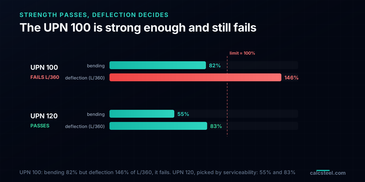
- A stair stringer is usually sized by deflection, not strength. On the worked 3.66 m flight a UPN 100 passes bending at 82 percent but its live deflection is 14.9 mm, 146 percent of the L/360 limit, so it fails. The UPN 120 that governs is chosen by serviceability, and the strength check never comes close.
- The load the code asks for is a uniform pressure that sizes the stringer and a concentrated load that sizes the tread, and they are not interchangeable. On plan the stair carries 4.79 kPa uniform under ASCE 7, plus a 1.33 kN point load that only the local tread ever sees.
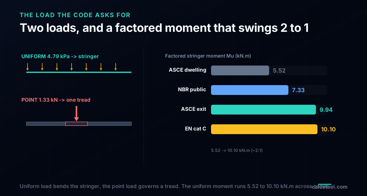
- Change the code and the same flight asks for a different moment. The factored stringer moment runs from 5.52 kN·m for a dwelling stair, through 7.33 kN·m for a Brazilian NBR public stair, up to 10.10 kN·m for a European category C public stair, a spread of nearly two to one on identical geometry.
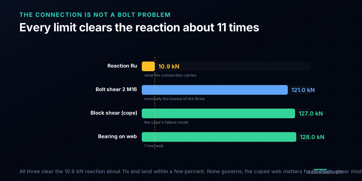
- The connection is not a bolt-shear problem. The 10.9 kN reaction is cleared about 11 times over by the bolts (121 kN), by bearing on the 7 mm channel web (128 kN) and by block shear at the coped end (127 kN). All three land within a few percent of each other, none of them governs, and the coped web matters for the block-shear failure mode it opens up, not for a smaller number.
- What governs an egress-stair connection is movement. The code asks it to accommodate a seismic relative displacement of about 72 mm on a 3.6 m storey, so the detail is designed to slide or to take that imposed drift, not to resist a larger force. Detailing, not the reaction, decides it.
Three problems wearing one handrail
A steel stair looks like the simplest thing in the building. Two sloping beams, some treads, a couple of connections at each end. It is also one of the most reliably mis-designed, because the three questions it asks have three different answers and people tend to give all three the same one.
The stringer is the inclined beam up each side of the flight. It carries the treads and everyone standing on them, and the instinct is to size it for bending. On a stair that instinct is usually wrong: the stringer is short, lightly loaded and slender, and it is deflection, not strength, that picks the section. The load feels like a fixed input, but the code hands you a uniform pressure and a concentrated point load, and which one matters depends on whether you are checking the stringer or a single tread. And the connection, the clip that ties the stringer to the landing beam, is the part most engineers oversize, because the end reaction it carries is tiny and the thing that really governs it is not a force at all. This guide takes one real egress flight, runs it on the CalcSteel engine, and answers each of the three on its own terms. For the stringer geometry in depth, why the moment follows the horizontal run while the deflection follows the true incline, the companion stair stringer guide is the deep dive; here the connection gets equal billing.
The assembly, and where the load goes
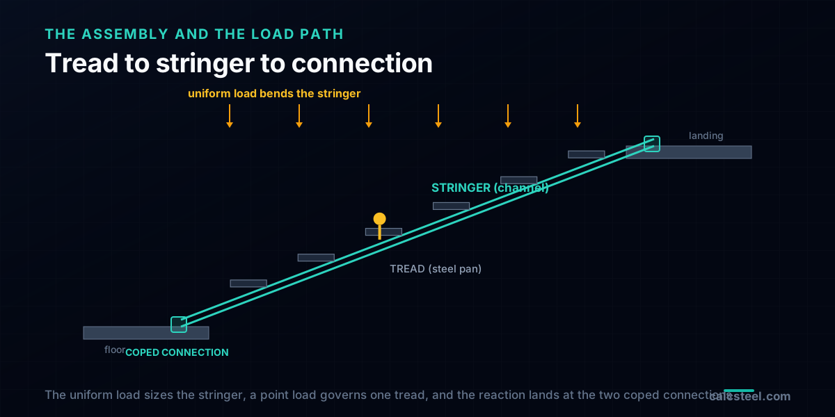
Follow a footstep down through the assembly. A person stands on a tread, a folded steel pan usually filled with a little concrete. The tread spans across the flight between the two stringers, the channels that run up each side at the slope of the stair. Each stringer is a simply supported inclined beam: it collects half the width of every tread and delivers the whole flight down to two connections, one at the floor and one at the landing.
That load path is the reason the three checks are separate. The uniform crowd load spreads along the stringer and bends it, so the stringer is a bending and deflection problem. A single heavy point, one person with a hand truck, lands on one tread and never reaches the stringer as a peak, so the tread is a local problem with its own governing load. And everything the stringer collects arrives at the two end connections as a modest reaction, so the connection is a detailing problem long before it is a strength one. Keep the three boxes apart and the stair designs itself; blur them and you size the connection for a load that is not there and miss the one that is.
The load the code asks for: two numbers, not one
Open any live-load table at the stair line and you find two entries, not one, and they do different jobs. The first is a uniform pressure, meant to represent a packed stair. Under ASCE 7-22 a stair and its exit carry 4.79 kPa, the 100 psf that also applies to the exit route it serves. EN 1991-1-1 ties the stair to the category of the area it links, so a public category C stair runs up to 5.0 kPa, while a home stair in category A takes 2.0. NBR 6120 asks 2.0 to 3.0 kPa depending on public access. This uniform load is what bends the stringer.
The second entry is a concentrated load, a single point meant to represent a boot, a jack or a piece of equipment on one step. ASCE 7 pairs its uniform with a 1.33 kN (300 lb) point load on a small patch; EN 1991-1-1 lists a category C stair point load up to 4.0 kN, and NBR 6120 a 2.5 kN one. The rule is that you check each element for whichever of the two produces the greater effect. For the stringer, spanning metres, the uniform load always wins. For a single tread, spanning the narrow width of the flight, the concentrated load usually wins. Design the tread for the point load and the stringer for the uniform, and never let one stand in for the other. The factors that turn these characteristic loads into a design demand are the subject of the load combinations guide.
The worked flight
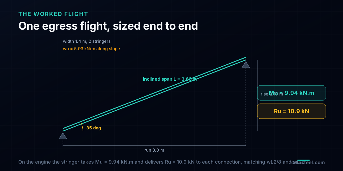
Here is the stair this guide sizes. One straight egress flight, clear width 1.4 m, rising 2.10 m over a horizontal run of 3.0 m, so it climbs at 35 degrees and the stringers span an inclined length of L = 3.66 m. Two channel stringers share the width, so each one carries a tributary strip 0.7 m wide. The treads are a steel pan with a light concrete fill.
Take the loads down to one stringer. The uniform live load is 4.79 kPa on plan and the dead load about 2.0 kPa; over the 0.7 m tributary, and projected onto the slope, that is a live line load of 2.75 kN/m and a dead line load of 1.28 kN/m along the stringer. Factored with 1.2D + 1.6L the design load is 5.93 kN/m. Run that on the engine as a simply supported beam of span L and it returns the two numbers the rest of the design leans on: a midspan moment Mu = 9.94 kN·m and an end reaction Ru = 10.9 kN. Both match the hand check wL²/8 and wL/2 exactly. Note which is which: the moment sizes the stringer, the reaction is everything the connection will ever be asked to carry.
Sizing the stringer: strength passes, deflection decides
Start with strength. The stringer is braced against lateral movement by the treads at every step, so it develops its full plastic moment. A UPN 100 channel in S275 has a plastic modulus Wpl = 49.0 cm³, giving a design capacity of φMn = 12.1 kN·m against the demand of 9.94 kN·m. That is 82 percent: it passes bending comfortably. On strength alone you would stop here and call the UPN 100 the answer.
Now check deflection, and the answer changes. Stairs are held to a tight limit, L/360 under live load, both because a bouncy stair feels unsafe and because people notice deflection underfoot far more than they notice it overhead. On this 3.66 m span that limit is 10.2 mm. The UPN 100 deflects 14.9 mm under the live load alone, which is 146 percent of the limit: it fails serviceability by half again, even though it had strength to spare. Step up to a UPN 120 (Ix = 364 cm⁴, 13.4 kg/m) and the deflection drops to 8.4 mm, 83 percent of the limit, while the bending utilisation falls to 55 percent. The section is chosen by deflection, and the strength check is along for the ride. This is the norm on stairs, not the exception, and it is why the serviceability limit is the one to run first. The reason the moment and the deflection scale differently with the slope is the subject of the stringer companion.
What the connection is actually asked to carry
Everything the stringer collects arrives at its two ends as a reaction of Ru = 10.9 kN. That is the entire force the connection carries in gravity, and it is small, smaller than a single person's weight multiplied through the load factors would suggest, because the stringer is short and only takes half the flight. The usual detail is a channel coped at the top so its flange clears the landing beam, with its web bolted to a fin plate or a pair of clip angles welded to that beam.
The instinct at this point is to count bolts against the reaction and move on. That is the instinct to resist, for two reasons that the next two sections make concrete. First, the reaction is so small that every strength limit in the connection clears it many times over, so counting bolts tells you almost nothing. Second, cutting the cope removes exactly the material the reaction passes through and opens a block-shear failure path the fasteners do not have, so the detail to watch is the notched web, not the bolt count. The connection is a geometry problem, not an arithmetic one.
The bolts are not the weak link, and neither is the web
Line the three strength limits up against the 10.9 kN reaction, using two M16 grade 8.8 bolts through the 7 mm channel web, the smallest bolt group anyone would detail:
| Limit state | Capacity | vs 10.9 kN |
|---|---|---|
| Bolt shear (2 × M16 8.8) | 121 kN | 11× over |
| Bearing on the 7 mm web | 128 kN | clears it |
| Block shear at the coped end | 127 kN | clears it |
Every line clears the reaction by about a factor of 11. Two M16 bolts in single shear are good for 121 kN, thirty times what two bolts on a beam this size would normally be asked to do. So the connection is not sized by force. It is sized by the minimum-detailing rules, two bolts because one is never allowed, a minimum weld leg, minimum edge distances, and by the movement in the next section.
The one number worth reading off the table is how close the three are. Bolt shear (121 kN) is nominally the lowest, with block shear (127 kN) and bearing on the 7 mm web (128 kN) a few percent above it, so all three land within about six percent of each other and every one clears the reaction close to eleven times. No strength check is the weak link here, and picking the smallest of three numbers that are all an order of magnitude too big tells you nothing about what the connection needs. If you ever do load a stair connection heavily, a landing beam framing into it, a long flight, it is the coped web you check first, through bearing and tear-out and block shear, not the bolt shear, because block shear is the failure mode the cope introduces.
The cope is where a stair connection fails
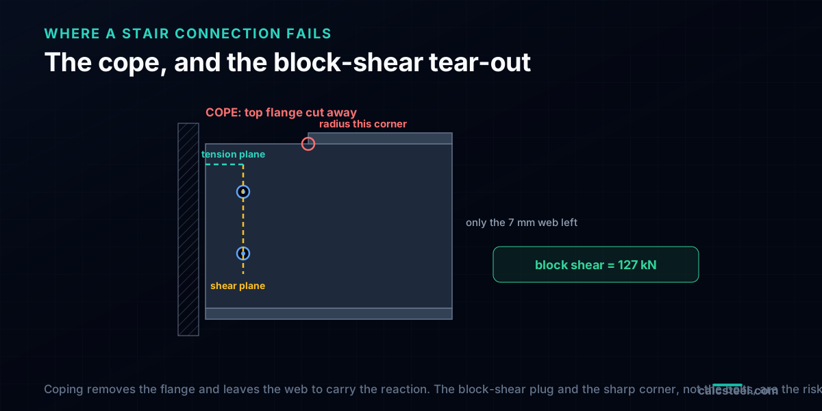
The coped end deserves its own look, because it is the one place a stair connection genuinely does fail when it fails. To sit the stringer against the landing beam, the top flange is cut away and only the web is left to carry the reaction into the bolts. That notch does three things at once: it removes the flange that braced the web, it concentrates stress at the re-entrant corner, and it sets up the block shear tear-out path, a plug of web that wants to pull out along the bolt line in shear and across to the free edge in tension.
For our detail the block shear capacity is 127 kN, computed on the 7 mm web with a shear plane down the two bolts and a tension plane out to the coped edge, per EN 1993-1-8. Against a 10.9 kN reaction it is not close, but the check still matters, because it is the limit that shrinks fastest if anything goes wrong: a sharp re-entrant corner that starts a crack, a shorter edge distance, a deeper cope, a heavier reaction from a landing. The two details that keep a coped stringer honest are a radiused cope corner rather than a square one, and enough edge distance that the tension plane has material to fail through. Neither shows up in a bolt count, which is why the bolt count is the wrong thing to have been staring at.
The load the code really asks of the connection: movement
If gravity does not govern the connection, what does. For an egress stair the answer is in the seismic chapter, and it is not a force but a displacement. A stair ties two floors together, and when the building sways those two floors move relative to each other. A stair connection rigid at both ends would be dragged into that story drift and could tear, or worse, could stiffen the frame in a way the analysis never accounted for and then fail brittle.
ASCE 7-22 therefore asks the connection to accommodate the seismic relative displacement between the levels it joins. On a 3.6 m storey at a 2 percent drift ratio that is about Dp = 72 mm of movement, and the standard detail answers it not by getting stronger but by getting looser: one end of the flight sits on a slotted or sliding connection that lets the floors move without loading the stair. That is the real design action on a stair connection. It is why a stair clip is often a humble two-bolt affair carrying a reaction it could hold ten times over, yet still has to be detailed with care, because the thing it is being asked to survive is the building moving around it, not the people standing on it.
Try it: get the reaction your connection carries
The connection check begins with the reaction, and the reaction comes from the stringer analysis, not from a rule of thumb. Enter your own flight below as a simply supported beam: the inclined span, the pinned and roller supports at the two ends, and the along-slope line load from your uniform pressure and tributary width. Read the support reaction, and that is the number every connection limit above has to beat. Read the midspan moment and the deflection in the same run, and you have sized the stringer and the connection from one model. Change the span or the load and watch all three move together.
Max moment
45 kN·m
Max shear
30 kN
Max deflection
10.55 mm
= L/569
Bending stress σ
84.4 MPa
σ = M/Sx
Utilization
44.0%
NBR 8800 · δ ≤ L/250
Geometry & supports
Section
Ix 7999 cm⁴ · Sx 533 cm³ · 42.2 kg/m
Point loads (↓ positive)
None — add as many as you need.
Distributed loads (uniform or trapezoidal)
Model sketch
Diagrams — free PNG / SVG / CSV export, no watermark
Step-by-step — the calculation memory of YOUR beam
IPE 300 · L = 6 m · fy = 250 MPa
1. Reactions (equilibrium of the solved FEM model)
ΣFy = 0 · ΣM = 0
R_A = 30 kN · R_B = 30 kN
2. Peak shear (read from the SFD)
Vmax = |V(x)|max
Vmax = -30 kN @ x = 6 m
3. Peak moment (read from the BMD)
Mmax = |M(x)|max
Mmax = 45 kN·m @ x = 3 m
4. Peak deflection
EI = 15998 kN·m² (E = 200 GPa)
δmax = 10.55 mm @ x = 3 m = L/569
5. Elastic bending stress
σ = Mmax / Sx = 45.00 × 10³ / 533.3
σ = 84.4 MPa
6. Bending check — both codes, side by side
NBR 8800: σ ≤ fy/1.10 = 227.3 MPa · AISC 360: σ ≤ 0.90·fy = 225 MPa
NBR 37.1% PASS · AISC 37.5% PASS
7. Deflection check (serviceability — code-independent)
δ ≤ L/250 = 24 mm
10.55 mm / 24 mm = 44.0% PASS
Recomputed live from the current inputs by the direct-stiffness FEM engine — change any load and every step updates. Reproduce it by hand with the formulas in the sections below.
Lightest catalog profiles that pass (974 flexural candidates · NBR 8800)
| Profile | Std | Weight | Total steel | σ util | δ util | |
|---|---|---|---|---|---|---|
| W310x21 | AISC | 21 kg/m | 126 kg | 83% | 98% | |
| VS 300x23 | BR | 22.6 kg/m | 136 kg | 71% | 84% | |
| U 300x90x6.3 | BR | 23.1 kg/m | 139 kg | 82% | 98% | |
| U 300x100x6.3 | BR | 24.1 kg/m | 145 kg | 77% | 91% | |
| VS 250x25 | BR | 24.6 kg/m | 148 kg | 70% | 100% |
Elastic bending (σ = M/Sx vs fy/γa1, γa1 = 1.10 — NBR 8800) + deflection screening of the full flexural catalog. Lateral-torsional buckling, shear and local buckling are NOT checked here — run the full NBR 8800 / AISC 360 verification in the 3D editor.
Five ways steel stairway design goes wrong
The failures repeat, and every one is a case of answering one of the three questions with another one's answer:
1. Sizing the stringer for strength. Picking the section on bending and never running L/360, so a stair that is strong enough is delivered bouncy and gets rejected on site.
2. Designing the tread for the uniform load. Or the stringer for the concentrated one. Each element takes whichever of the two code loads governs it, and they are rarely the same load.
3. Counting bolts and stopping. Sizing the connection for the reaction, finding an enormous margin, and declaring it done, while the coped web and the seismic movement, the two things that actually govern, go unchecked.
4. A square cope corner. Leaving a sharp re-entrant notch that starts a fatigue or brittle crack, instead of radiusing it. The cheapest detail on the drawing and the most common origin of a real stair failure.
5. A rigid stair in a flexible frame. Fixing both ends of an egress flight so the building's drift loads it, instead of letting one end slide to absorb the relative displacement the seismic code asks for.
Key takeaways
- A stair stringer is sized by deflection, not strength: the UPN 100 passes bending at 82 percent but fails L/360 at 146 percent, so the UPN 120 is chosen by serviceability.
- The code asks for a uniform load that sizes the stringer (4.79 kPa under ASCE 7) and a concentrated load that sizes the tread (1.33 kN); check each element for whichever governs it.
- The factored stringer moment runs from 5.52 kN·m for a dwelling to 10.10 kN·m for a European category C public stair on identical geometry, a near two-to-one code spread.
- The connection is not a bolt-shear problem: the 10.9 kN reaction is cleared about 11× by the bolts, the web bearing and the block shear, all three within a few percent and none governing; the coped web matters for its block-shear failure mode, not a smaller capacity.
- What governs an egress-stair connection is the seismic relative displacement (about 72 mm here), so it is detailed to move, not to resist a larger force.
Sources
- 1.ASCE/SEI 7-22, Minimum Design Loads and Associated Criteria for Buildings and Other Structures (Table 4.3-1 stair live loads; Chapter 13 seismic design of nonstructural components)
- 2.AISC Design Guide 34, Steel-Framed Stairway Design
- 3.AISC 360-22, Specification for Structural Steel Buildings (Chapter J connections, J4.3 block shear)
- 4.EN 1991-1-1:2002, Eurocode 1, Actions on structures, imposed loads on stairs (Table 6.2); EN 1993-1-8 bolted connections and block tearing
- 5.ABNT NBR 6120:2019, Acoes para o calculo de estruturas de edificacoes (cargas em escadas)
- 6.Salmon, Johnson and Malhas, Steel Structures: Design and Behavior
Try CalcSteel for free
Model, analyze and design steel structures in your browser. No install, no signup.
Open the 3D editor