Section Classification: Compact, Noncompact and Slender, Decided by Two Ratios
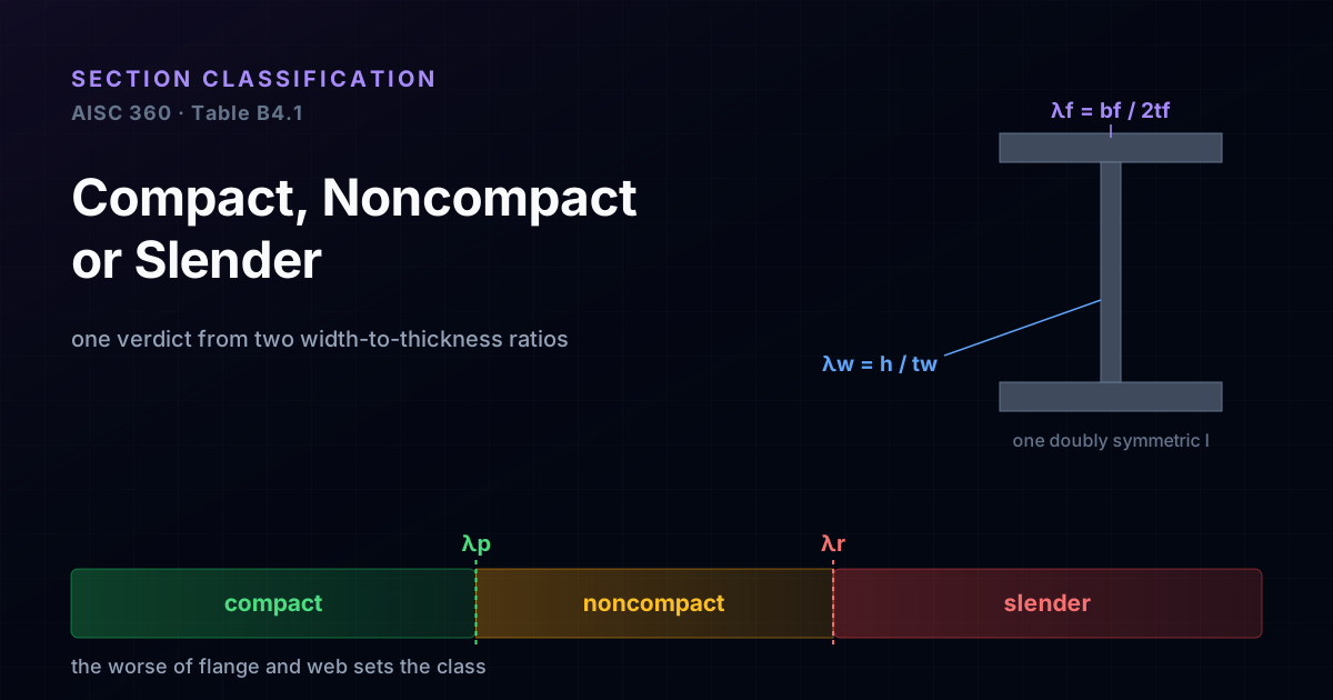
Before a steel beam has a moment capacity, its cross-section gets a verdict: compact, noncompact or slender. That verdict decides whether the shape can reach its full plastic moment or whether a thin plate buckles locally first and caps the strength below it. AISC reduces the whole question to two width-to-thickness ratios, one for the flange and one for the web, each compared with two limits. This guide shows where the ratios and the limits come from and works three real sections end to end, a rolled IPE 400, a welded VS 600x81 and a slender-web plate girder, with every number computed from the section geometry.
Key takeaways
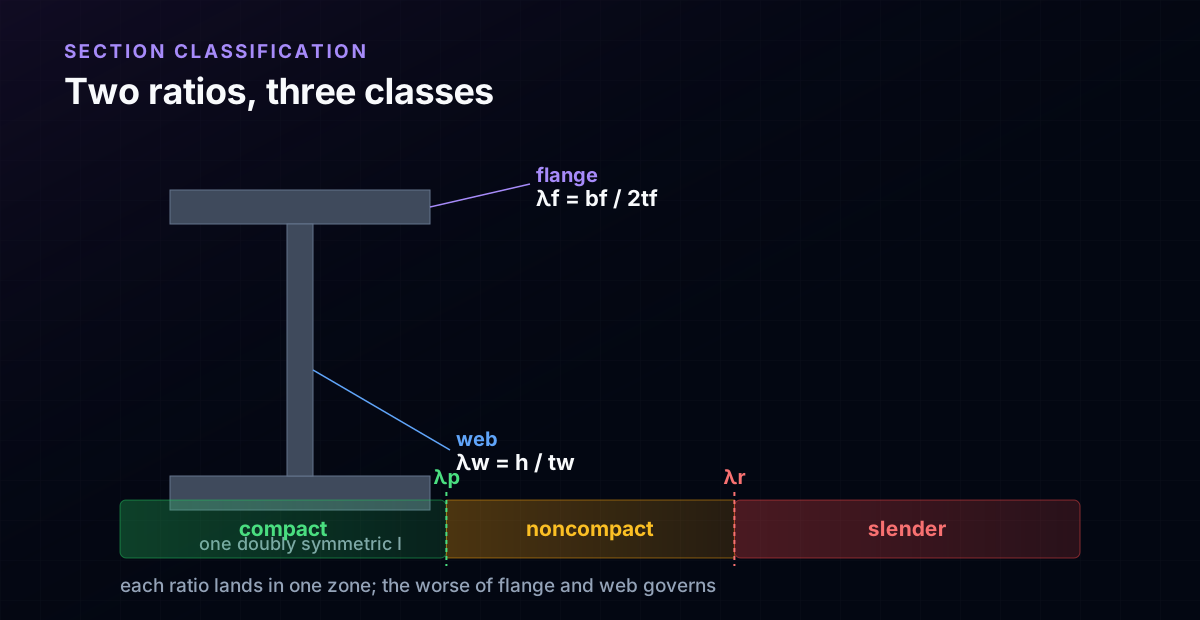
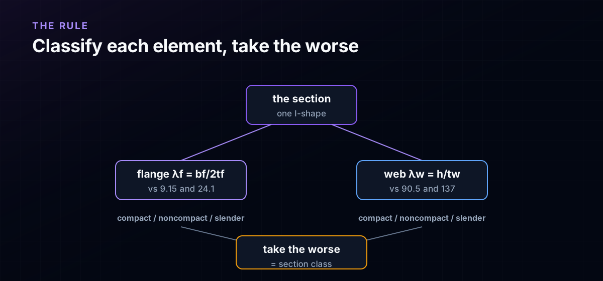
- A section's flexural class comes from two width-to-thickness ratios: the flange λf = bf/(2tf) and the web λw = h/tw. Each is compared with two limits, λp (compact) and λr (slender), and the WORSE of the flange and web verdicts governs the whole section.
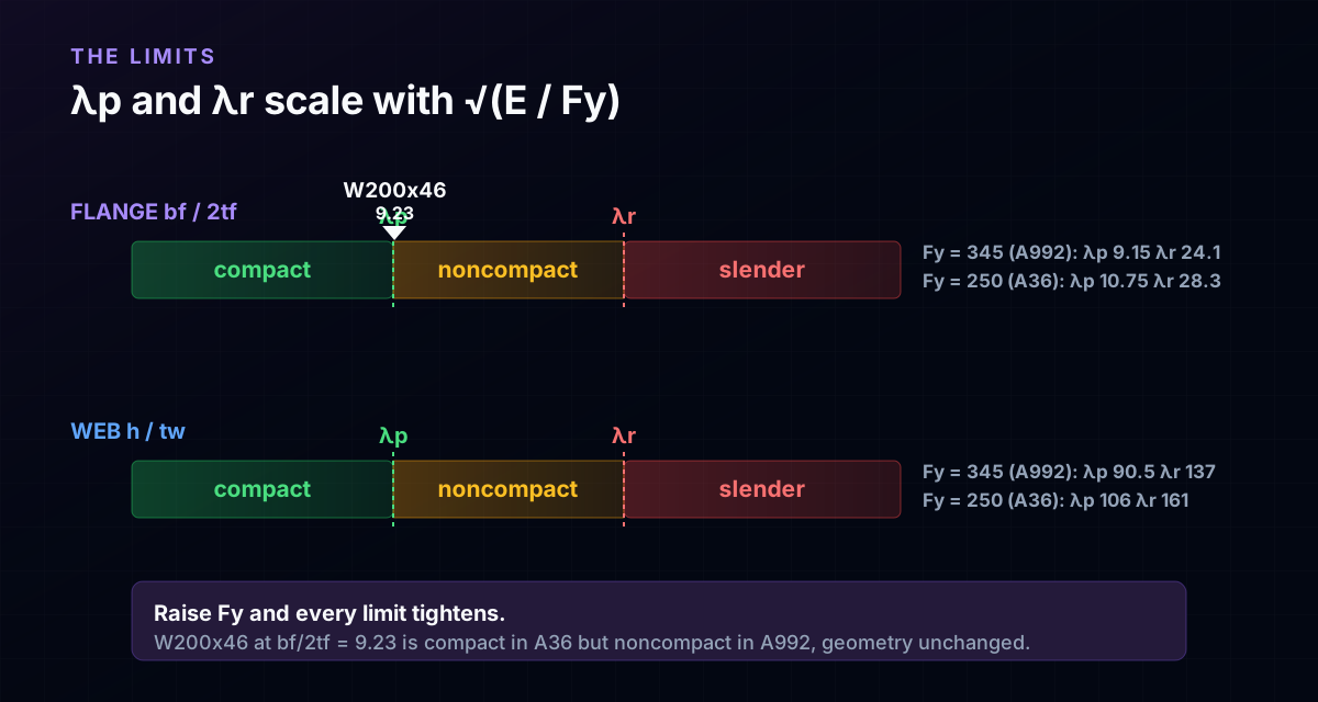
- The limits scale as √(E/Fy). For A992 steel (Fy = 345 MPa, 50 ksi) the flange limits are λp = 0.38√(E/Fy) = 9.15 and λr = 24.1; the web limits are λp = 3.76√(E/Fy) = 90.5 and λr = 137. Higher yield stress makes every limit stricter, so classification depends on the steel grade, not the geometry alone.
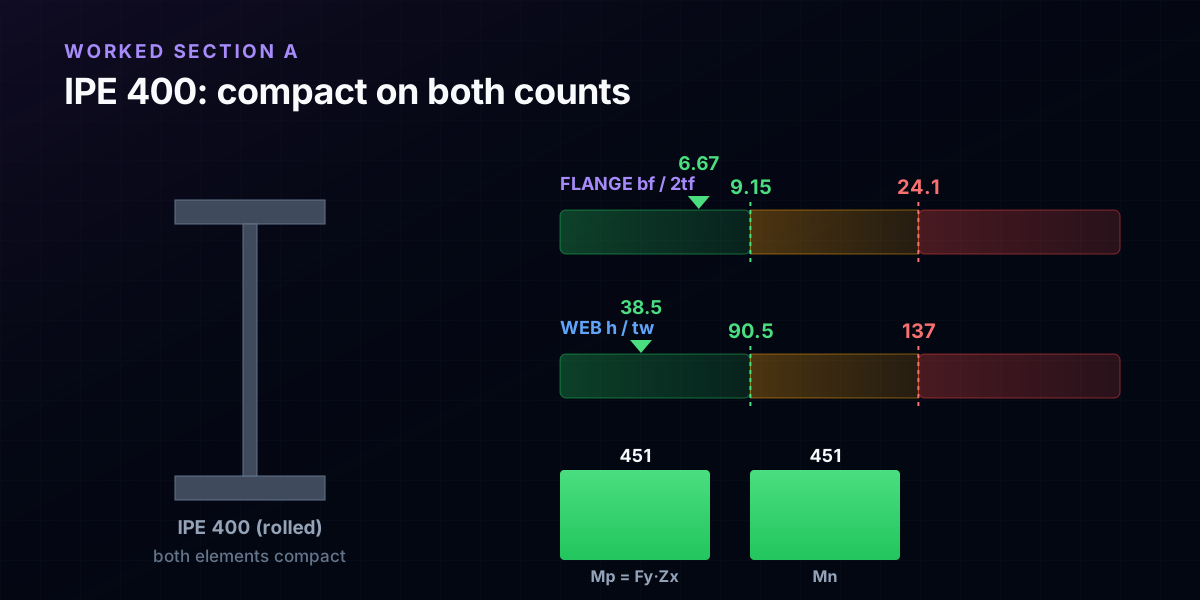
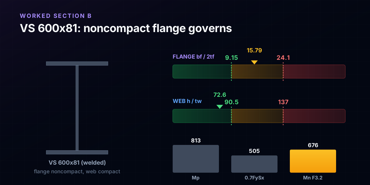
- Compact means the section reaches Mp = Fy·Zx (rolled IPE 400: bf/2tf = 6.67, h/tw = 38.5, both compact, Mp = 451 kNm). Noncompact means a flange or web buckles after first yield, so the AISC F3.2 line drops the capacity from Mp toward 0.7·Fy·Sx (welded VS 600x81: noncompact flange λf = 15.8, Mn = 676 kNm, 83% of Mp).
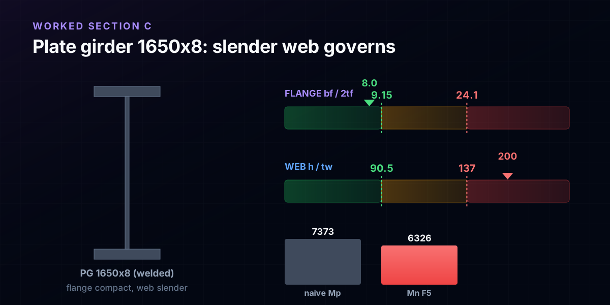
- Slender means a plate buckles while still elastic. A 1650 mm plate girder with an 8 mm web (h/tw = 200 > 137) lands in AISC F5: you forfeit the plastic reserve and multiply by the web reduction factor Rpg = 0.95, giving Mn = Rpg·Fy·Sx = 6326 kNm, well under the naive Mp of 7373 kNm.
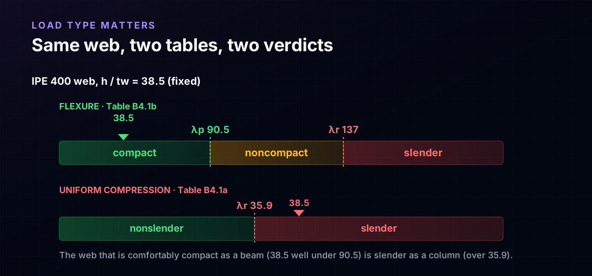
- The load type changes the table. Flexure has three classes (Table B4.1b); uniform compression has only two, nonslender and slender, with much stricter limits (Table B4.1a). The same IPE 400 whose web is comfortably compact as a beam (38.5 << 90.5) is already slender as a column (38.5 > 1.49√(E/Fy) = 35.9).
The verdict every section gets before it has a capacity
Ask a steel beam for its moment capacity and the code asks a question first: can this cross-section actually develop the stress you are counting on, or will a thin plate in it buckle locally and give up early? That question has a one-word answer, the section class, and it is one of three: compact, noncompact or slender.
The class is not a detail. It decides which equation you are even allowed to use. A compact section can yield all the way through and reach its full plastic moment Mp. A noncompact section yields at the extreme fibre but a flange or web buckles before the whole section plastifies, so the usable moment sits below Mp. A slender section has a plate so thin it buckles while the steel is still elastic, well before yield, and the capacity drops further still. Same steel, same span, three very different numbers, chosen by geometry.
The good news is that the whole verdict comes from just two ratios. For a doubly symmetric I-shape you measure how stocky the flange is and how stocky the web is, compare each against two limits, and read off the class. This guide is written for the student meeting AISC Table B4.1 for the first time, and for the practising or freelance engineer who wants the three worked cases that make the table concrete. Every number below is computed from the real section geometry, at Fy = 345 MPa (the 50 ksi grade used in most of the flexure literature), and hand-checked against the AISC provisions.
Why a plate cares about its width-to-thickness ratio
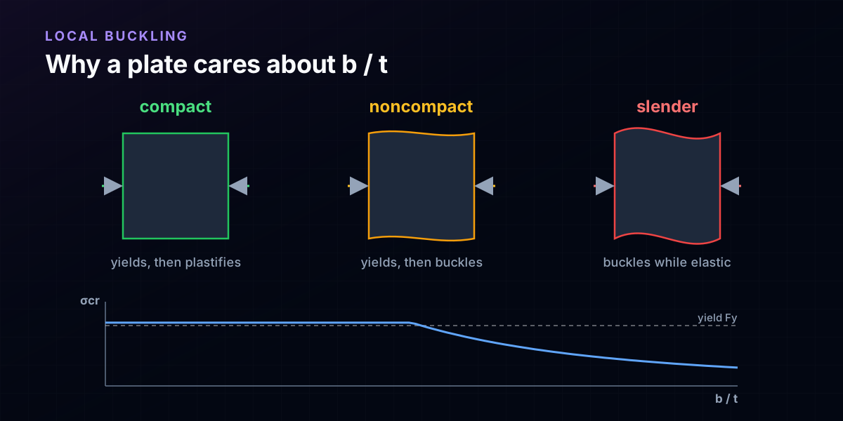
The physics under the whole subject is plate buckling. A flat plate under edge compression does not fail by squashing; it buckles sideways out of its plane at a stress that depends almost entirely on how wide it is relative to how thick, the ratio b/t. A stocky plate, low b/t, can be pushed all the way to yield and beyond before it buckles. A thin plate, high b/t, buckles elastically at a stress far below yield.
Now picture the flange and web of a beam at the moment the section is trying to develop its full strength. Both are plates in compression on the compression side. If they are stocky enough, they hold their shape while the fibres yield and the section plastifies, and the beam delivers Mp. If they are too thin, one of them ripples and buckles first, and the beam never reaches the moment its yield stress promised.
The three classes are just three positions on that curve. Compact: the plate reaches yield and can sustain the strain needed to plastify the section, so no local penalty. Noncompact: the plate reaches yield at the surface but buckles before the section fully plastifies, so you lose the plastic reserve. Slender: the plate buckles while still elastic, so you cannot even reach yield on the gross section. Classification is the code turning that continuous plate-buckling behaviour into three design regimes, with two limits marking the borders.
The two ratios, and why the flange and web differ
For a doubly symmetric I-shape in bending, two elements can buckle, so you measure two ratios.
The flange ratio, λf = bf/(2tf). The compression flange is an unstiffened plate: it is supported by the web along one edge and free along the other. You take half the flange width bf/2, the outstand from the web to the tip, over the flange thickness tf. A wide, thin flange has a high λf and buckles readily.
The web ratio, λw = h/tw. The web is a stiffened plate: it is held by a flange along both of its long edges. Here h is the clear web depth (between the flanges, less the fillets for a rolled shape) and tw is the web thickness. A deep, thin web has a high λw.
The edge support is the reason the two elements have completely different limits. A plate held on both edges is far harder to buckle than a plate free on one edge, so the web is allowed a much larger ratio before it gets into trouble. That is why, as you will see, the flange compact limit is around 9 while the web compact limit is around 90: the same steel, but ten times the slenderness tolerated, purely because the web has support on both sides and the flange does not.
Two other rules follow from the same idea. Use the correct b: for the flange it is the outstand bf/2, not the full width; for a rolled web, h excludes the fillets. And these are the ratios for a doubly symmetric I bent about the strong axis. Channels, tees, angles and HSS have their own element definitions in Table B4.1, but the logic, stocky plate versus thin plate, is identical.

Where λp and λr come from, and why Fy is in them
Each ratio is compared with two limits. λp is the compact limit: at or below it, the element can plastify, and the section keeps its plastic reserve. λr is the slender limit: above it, the element buckles elastically. Between them, the element is noncompact.
Both limits scale with √(E/Fy), and that square root carries the whole physics. The buckling capacity of the plate depends on the stiffness E; the demand is set by the yield stress Fy you are trying to reach. Raise Fy and you are asking the same plate to hold a higher stress without buckling, so the limit on b/t must tighten. Classification therefore depends on the steel grade, not on geometry alone.
For a doubly symmetric I in flexure (AISC 360 Table B4.1b), with E = 200 GPa and Fy = 345 MPa (A992, 50 ksi, so √(E/Fy) = 24.08):
- Flange: λp = 0.38√(E/Fy) = 9.15, λr = 1.0√(E/Fy) = 24.1.
- Web: λp = 3.76√(E/Fy) = 90.5, λr = 5.70√(E/Fy) = 137.
Drop to A36 steel (Fy = 250 MPa) and every limit loosens: the flange λp rises to 10.75, λr to 28.3. That shift is not academic. Take a real rolled beam, a W200x46, whose flange ratio is bf/(2tf) = 9.23. In A36 it sits under the 10.75 limit and is compact. In A992 the limit has tightened to 9.15, and the very same beam, not one millimetre changed, is now noncompact. When someone quotes a section as compact, the honest question is always: compact at what Fy?
Two ratios, one verdict: the worse element governs
You now have two ratios and, for each, two limits. Classifying the section is three steps.
- Compute λf = bf/(2tf) and put it in a bin: compact if λf ≤ λp,f, slender if λf > λr,f, noncompact in between.
- Compute λw = h/tw and bin it the same way against the web limits.
- The section class is the worse of the two. A compact flange cannot rescue a slender web, and a compact web cannot rescue a noncompact flange.
That last rule is the one people forget. A section with a beautifully stocky web and one thin flange is a noncompact section, and its capacity is governed by the flange, not the web. In practice one element almost always governs and the other is comfortably inside its limit, which is why experienced engineers glance at the flange of a rolled beam and the web of a deep plate girder first. But you have to check both, because the governing element is not always the one you expect.
The three worked sections that follow are chosen so each class is decided by a different element: a rolled beam that is compact on both counts, a welded girder whose flange is noncompact while its web is fine, and a plate girder whose web is slender while its flange is fine.
Worked section A: a compact rolled beam, IPE 400
Start with an ordinary hot-rolled beam, an IPE 400 in A992 steel (Fy = 345 MPa). Its geometry: flange width bf = 180 mm, flange thickness tf = 13.5 mm, web thickness tw = 8.6 mm, clear web depth h = 331 mm.
Flange: λf = bf/(2tf) = 180/(2·13.5) = 6.67. The compact limit is 9.15, so 6.67 ≤ 9.15: compact.
Web: λw = h/tw = 331/8.6 = 38.5. The compact limit is 90.5, so 38.5 ≤ 90.5: compact.
Both elements are compact, comfortably, so the section is compact and it develops its full plastic moment:
Mp = Fy·Zx = 345 MPa · 1307 cm³ = 451 kNm
using the catalog plastic modulus Zx = 1307 cm³. No local-buckling penalty applies. The only thing that can now reduce the moment capacity below Mp is lateral-torsional buckling, an unbraced-length effect that is a separate chapter, not a section-class effect. This is the case rolled beams are designed to be: the mills proportion standard I-shapes so that in ordinary grades the flange and web are both compact, which is exactly why a compact section is the default assumption a quick beam check makes.
Worked section B: a noncompact flange, welded VS 600x81
Now a Brazilian welded plate girder, a VS 600x81, the kind of built-up beam a fabricator makes by welding three plates. Its flange is a 300 mm plate only 9.5 mm thick; the web is 8.0 mm thick over a clear depth of 581 mm.
Flange: λf = 300/(2·9.5) = 15.79. This is above the compact limit 9.15 but below the slender limit 24.1, so the flange is noncompact.
Web: λw = 581/8.0 = 72.6 ≤ 90.5, so the web is compact.
The worse verdict governs: the section is noncompact, and the flange is the culprit. Because the flange yields but buckles before the section fully plastifies, AISC F3.2 draws a straight line for Mn between the plastic moment at λp and the value 0.7·Fy·Sx at λr:
Mn = Mp − (Mp − 0.7·Fy·Sx)·(λf − λp)/(λr − λp)
With Zx = 2358 cm³ and Sx = 2092 cm³, the anchors are Mp = 345·2358 = 813.5 kNm and 0.7·Fy·Sx = 505.2 kNm. The flange sits a fraction (15.79 − 9.15)/(24.1 − 9.15) = 0.445 of the way along the line, so:
Mn = 813.5 − (813.5 − 505.2)·0.445 = 676 kNm, about 83% of Mp.
That 17% is the price of the thin flange. Nothing about the analysis, the loads, or the yield stress changed; the section simply cannot cash its full plastic moment because the flange rippling caps it. Thicken that flange to 16 mm and λf drops to 9.4, nearly compact, and almost all of the reserve comes back. This is where classification pays for itself: it tells you exactly how much moment a proportion choice is costing you.
Worked section C: a slender web, a 1650 mm plate girder
The third case is where slender actually lives: a tall, thin-webbed welded plate girder, the workhorse of crane runways and bridges. Take a 1650 mm deep girder with compact 400 x 25 mm flanges and a web only 8 mm thick over a 1600 mm clear depth.
Flange: λf = 400/(2·25) = 8.0 ≤ 9.15, compact.
Web: λw = 1600/8 = 200. The slender limit is 137, and 200 > 137, so the web is slender.
A slender web changes the chapter. You leave the compact and noncompact provisions and enter AISC F5, the plate-girder section, and you pay twice. First, a slender web cannot develop yield over its full depth, so the capacity is built on the elastic section modulus Sx, not the plastic Zx: you forfeit the plastic reserve outright. Second, F5 multiplies by a web bend-buckling reduction factor Rpg, which accounts for the post-buckled web shedding stress toward the flanges:
Rpg = 1 − aw/(1200 + 300·aw)·(h/tw − 5.70√(E/Fy)) ≤ 1.0
with aw = (h·tw)/(bf·tf) = (1600·8)/(400·25) = 1.28. That gives Rpg = 0.95. With Sx = 19315 cm³ and the compact flange developing Fcr = Fy:
Mn = Rpg·Fy·Sx = 0.95 · 345 · 19315 = 6326 kNm
Compare that with the plastic moment a careless calculation would report, Mp = Fy·Zx = 7373 kNm. The slender web costs about 14% relative to that Mp, and more importantly it puts you in a design regime with its own shear, stiffener and flexure rules. Note the honest fact underneath this example: no rolled shape reaches a slender web, and even the deep welded girders in a standard catalog top out around h/tw = 120, still noncompact. Slender webs are something you build, by welding a web plate thinner than any rolled section, which is exactly why plate girders carry transverse stiffeners.
Change the load, change the table: compression has only two classes
Everything so far was flexure, AISC Table B4.1b, with three classes. Put the same section in uniform axial compression and you switch to Table B4.1a, which has only two classes: nonslender and slender. There is no compact for a column, because a column has no plastic-moment reserve to protect; the only question is whether the element buckles locally before the whole member reaches its squash load, so a single limit λr separates nonslender from slender.
The compression limits are also far stricter, because a column loads the entire flange and web in uniform compression rather than the triangular stress a beam sees. For the same A992 steel: the unstiffened flange limit is 0.56√(E/Fy) = 13.5, and the stiffened web limit is 1.49√(E/Fy) = 35.9, against the flexural web compact limit of 90.5.
Run our compact IPE 400 through the compression table. Flange: bf/(2tf) = 6.67 ≤ 13.5, nonslender. Web: h/tw = 38.5, and now the limit is 35.9, so 38.5 > 35.9: the web is slender. The very same web that was comfortably compact as a beam (38.5 well under 90.5) is slender as a column, which triggers an effective-area reduction (the Q or the effective-width provisions) on the compression capacity. One section, one geometry, two completely different verdicts, because bending and pure compression ask the plate two different questions. Always classify for the load case you are in.
So what the class actually changes
Classification is never the end goal; it is the switch that selects the strength equation. Pulling the three cases together, in flexure:
- Compact: Mn = Mp = Fy·Zx. Full plastic moment, the plastic modulus, no local penalty. (Lateral-torsional buckling may still cut it, separately.)
- Noncompact: Mn interpolates linearly from Mp down to 0.7·Fy·Sx as the governing ratio runs from λp to λr. You keep first yield but lose the plastic reserve, in proportion.
- Slender: Mn is built on the elastic modulus Sx and reduced by a local-buckling factor (Rpg for the web in F5, or a reduced Fcr for a slender flange). You lose the plastic reserve entirely and take a buckling penalty on top.
In compression the switch is binary: a nonslender member uses its gross area, while a slender element forces an effective-area (or Q-factor) reduction that pulls the column capacity down. Either way, the class you assign is what decides whether you multiply by Zx or Sx, whether you interpolate or reduce, and whether you are in Chapter F3, F4 or F5. Get the two ratios right and the rest of the flexure calculation follows; get them wrong and every downstream number inherits the error.
Six ways a classification quietly goes wrong
None of these throws an error. Each just returns a confident, wrong class.
- Using the full flange width. The flange ratio is the outstand bf/(2tf), not bf/tf. Halving the flange width is the single most common slip, and it turns a noncompact flange into a falsely compact one.
- Ignoring Fy. The limits move with √(E/Fy). A section that is compact in A36 can be noncompact in A992, as the W200x46 showed. There is no such thing as a compact section without a stated grade.
- Assuming rolled means compact. Most rolled beams are compact in ordinary grades, but not all, and the moment you weld a built-up section the assumption is gone. Welded girders are where noncompact and slender live.
- Classifying for the wrong load. Flexure has three classes and generous web limits; uniform compression has two and strict ones. Use Table B4.1a for compression members and B4.1b for flexural members, and check both for a beam-column.
- Only checking the flange. The web governs deep, thin-webbed sections, and it governs almost every column. The worse of the two elements sets the class, so both must be checked.
- Trusting a beam calculator's Mp without the class. A quick beam tool typically reports Mp = Fy·Zx and a lateral-torsional check, implicitly assuming a compact section. For a welded or thin-walled shape that Mp can be optimistic; the classification is what tells you whether to believe it.
Try it on a real section
The fastest way to make this stick is to classify a section yourself. Open the beam calculator below, pick a shape, and read off its plastic moment Mp = Fy·Zx and its section properties. Then do the two ratios by hand from the geometry the tool shows: bf/(2tf) for the flange and h/tw for the web, each against 0.38√(E/Fy) and 1.0√(E/Fy) for the flange, 3.76√(E/Fy) and 5.70√(E/Fy) for the web. If both land compact, the Mp the calculator reports is the real capacity, subject only to the lateral-torsional check. If either lands noncompact or slender, that Mp is the ceiling and the true Mn sits below it, by the F3.2 interpolation or the F5 reduction you now know how to run.
That is the honest division of labour: the tool gives you the section properties and the plastic moment fast, and the two ratios tell you which strength equation those properties are actually allowed to use. From here, the natural next reads are the section properties that feed Sx and Zx, and torsional-flexural buckling, where the slender-element story continues on the compression side.
Max moment
45 kN·m
Max shear
30 kN
Max deflection
10.55 mm
= L/569
Bending stress σ
84.4 MPa
σ = M/Sx
Utilization
44.0%
NBR 8800 · δ ≤ L/250
Geometry & supports
Section
Ix 7999 cm⁴ · Sx 533 cm³ · 42.2 kg/m
Point loads (↓ positive)
None — add as many as you need.
Distributed loads (uniform or trapezoidal)
Model sketch
Diagrams — free PNG / SVG / CSV export, no watermark
Step-by-step — the calculation memory of YOUR beam
IPE 300 · L = 6 m · fy = 250 MPa
1. Reactions (equilibrium of the solved FEM model)
ΣFy = 0 · ΣM = 0
R_A = 30 kN · R_B = 30 kN
2. Peak shear (read from the SFD)
Vmax = |V(x)|max
Vmax = -30 kN @ x = 6 m
3. Peak moment (read from the BMD)
Mmax = |M(x)|max
Mmax = 45 kN·m @ x = 3 m
4. Peak deflection
EI = 15998 kN·m² (E = 200 GPa)
δmax = 10.55 mm @ x = 3 m = L/569
5. Elastic bending stress
σ = Mmax / Sx = 45.00 × 10³ / 533.3
σ = 84.4 MPa
6. Bending check — both codes, side by side
NBR 8800: σ ≤ fy/1.10 = 227.3 MPa · AISC 360: σ ≤ 0.90·fy = 225 MPa
NBR 37.1% PASS · AISC 37.5% PASS
7. Deflection check (serviceability — code-independent)
δ ≤ L/250 = 24 mm
10.55 mm / 24 mm = 44.0% PASS
Recomputed live from the current inputs by the direct-stiffness FEM engine — change any load and every step updates. Reproduce it by hand with the formulas in the sections below.
Lightest catalog profiles that pass (974 flexural candidates · NBR 8800)
| Profile | Std | Weight | Total steel | σ util | δ util | |
|---|---|---|---|---|---|---|
| W310x21 | AISC | 21 kg/m | 126 kg | 83% | 98% | |
| VS 300x23 | BR | 22.6 kg/m | 136 kg | 71% | 84% | |
| U 300x90x6.3 | BR | 23.1 kg/m | 139 kg | 82% | 98% | |
| U 300x100x6.3 | BR | 24.1 kg/m | 145 kg | 77% | 91% | |
| VS 250x25 | BR | 24.6 kg/m | 148 kg | 70% | 100% |
Elastic bending (σ = M/Sx vs fy/γa1, γa1 = 1.10 — NBR 8800) + deflection screening of the full flexural catalog. Lateral-torsional buckling, shear and local buckling are NOT checked here — run the full NBR 8800 / AISC 360 verification in the 3D editor.
Sources
- 1.AISC 360-22, Specification for Structural Steel Buildings, Section B4 and Table B4.1a/B4.1b (classification), Chapters F3, F4, F5 (flexural strength)
- 2.AISC Steel Construction Manual, 16th Edition, Part 1 (dimensions and properties) and Part 3 (design of flexural members)
- 3.Salmon, Johnson and Malhas, Steel Structures: Design and Behavior, chapter on local buckling and plate stability
- 4.ABNT NBR 8800, Projeto de estruturas de aço e de estruturas mistas de aço e concreto de edifícios, Anexo F (flambagem local)
Try CalcSteel for free
Model, analyze and design steel structures in your browser. No install, no signup.
Open the 3D editor