Roof Truss for a 15 m Span: Member Forces and the Governing Load Case
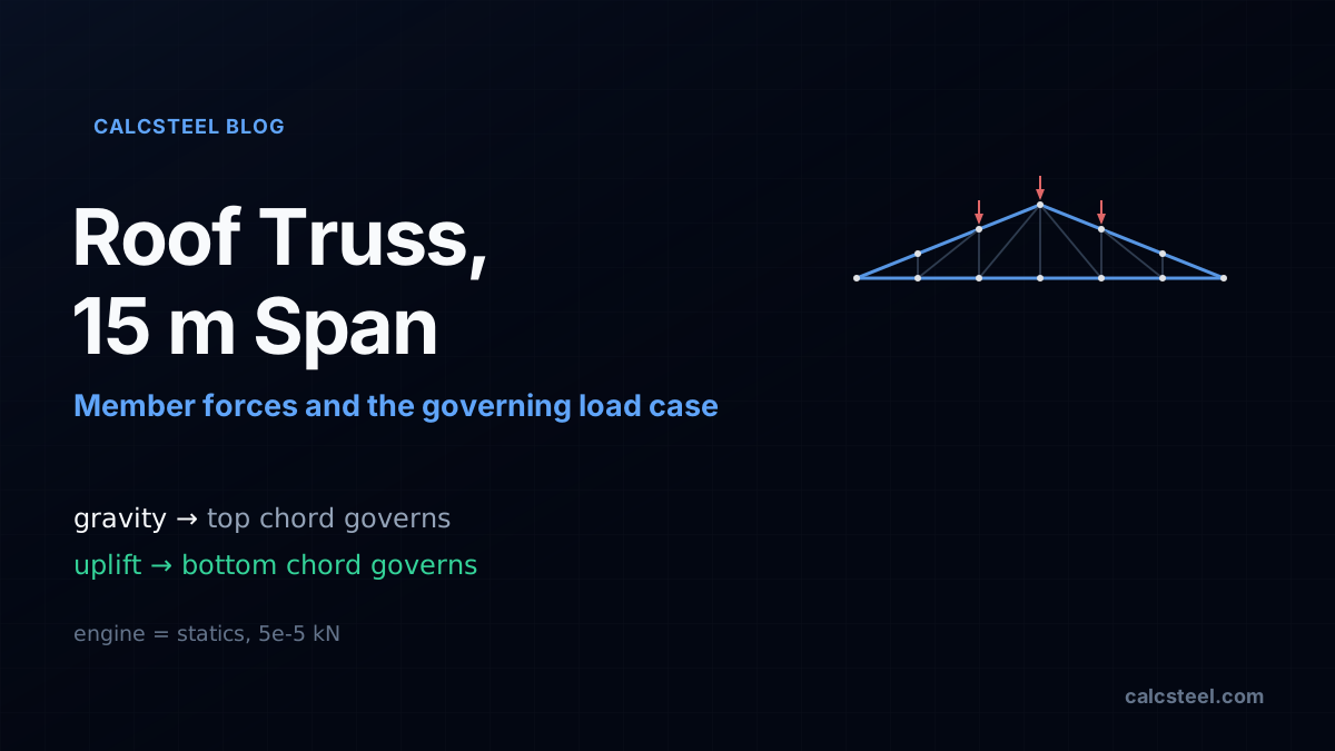
Designing a steel roof truss comes down to two questions: what is the axial force in every member, and which load case puts the worst force there. For a 15 m span they are not the same answer for every member. This guide takes one real duopitch truss, solves it on the CalcSteel FEM engine for dead, snow and wind, checks every member force against method-of-joints statics to the fifth decimal, and shows the wind uplift case quietly govern the members you would have sized for gravity.
Key takeaways
- A pin-jointed roof truss carries axial force only, so its members are governed by force, not moment. For our 15 m span, six-panel duopitch truss the engine returns pure axial members (zero bending) and matches an independent method-of-joints solution to 5e-5 kN across all three load cases.
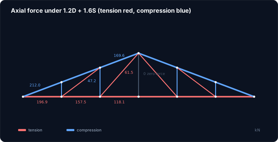
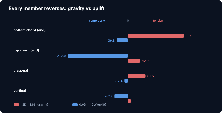
- Under the gravity combination 1.2D + 1.6S the pattern is the textbook one: the bottom chord is in tension (up to 196.9 kN in the end panel), the top chord is in compression (up to 212.0 kN), the diagonals carry tension and the verticals carry compression.
- Wind uplift reverses it. Under 0.9D + 1.0W every loaded member changes sign: the bottom chord end panel swings from 196.9 kN tension to 39.8 kN compression, and the top chord swings from 212.0 kN compression to 42.9 kN tension.
- That reversal decides which load case governs, member by member. The top chord is governed by gravity compression; the bottom chord is governed for strength by gravity tension, but its real sizing check is the uplift compression, because compression is buckling-limited.
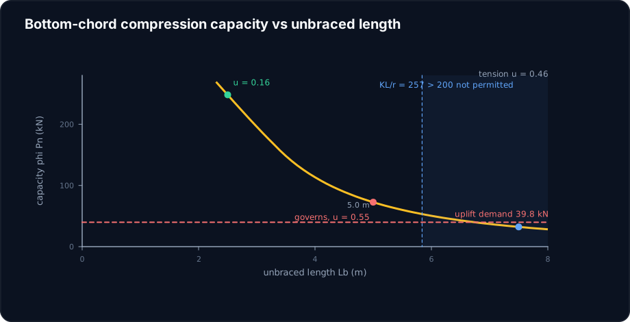
- With realistic third-point lateral bracing (unbraced length 5.0 m), a light HSS 76x76x4.8 bottom chord is at utilisation 0.46 in tension but 0.55 in uplift compression: the load case you might forget is the one that sizes the member. Brace it only at midspan and its slenderness KL/r reaches 257, past the code limit of 200, and it is not even permitted.
Two questions, and they do not share one answer
A steel roof truss is one of the most satisfying structures to design because almost everything about it reduces to a single quantity per member: the axial force. Idealise the joints as pins, load the truss at its panel points, and every member is a two-force member carrying pure tension or pure compression, no bending. Size each one for that force and you are most of the way to a set of drawings.
The catch is hidden in the word force. There are really two questions, not one. The first is what is the force in each member, which statics answers cleanly. The second is which load case produces the worst force there, and for a roof truss that answer is not the same for every member. A member that is comfortably in tension under gravity can be driven into compression by wind uplift, and compression is a different, harsher check. Miss the governing case for that member and you will size it for the wrong number.
This article works one concrete truss all the way through: a 15 m span duopitch roof truss, solved on the CalcSteel finite element engine for dead, snow and wind, with every member force cross-checked against hand statics. Then it lines up the load combinations and, member by member, finds the one that governs. The surprise, as usual, is the load case that is easiest to forget.
The worked truss: 15 m, six panels, one ridge
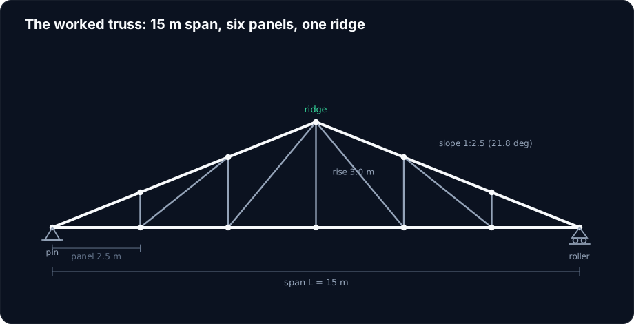
Here is the structure we carry through the whole article. It is a symmetric duopitch (triangular) truss spanning L = 15.0 m between supports, pinned at the left eave and on a roller at the right. The bottom chord is split into six panels of 2.5 m; the top chord rises from each eave to a ridge 3.0 m above the supports, a slope of 1:2.5 or about 21.8 degrees. Interior top-chord joints sit above every interior bottom-chord joint, and each panel is triangulated with a vertical and a diagonal.
Count the pieces: 12 joints, 21 members, 3 reactions. Since members + reactions (21 + 3 = 24) equals twice the joints (2 x 12 = 24), the truss is statically determinate: its member forces follow from equilibrium alone, independent of the section sizes. That is exactly why a truss is a good teaching structure, and why the engine result can be checked by hand to the last digit.
The trusses are spaced 5.0 m on centre along the building, so each one carries a 5.0 m wide strip of roof. Purlins deliver that strip to the truss as point loads at the top-chord panel points, which is where all our loads are applied.
Three load cases and the combinations that mix them
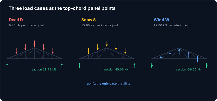
Three load cases reach this roof, and they do not act at full value together, so we keep them separate and combine them afterward. Taken over the 5.0 m truss spacing and the 2.5 m panel, each interior top-chord joint collects the load from one 2.5 m x 5.0 m patch of roof; the eave joints collect half a panel.
- Dead load D, the roofing, purlins and the truss itself, about 0.50 kN/m2. Per interior joint that is 0.50 x 2.5 x 5.0 = 6.25 kN down.
- Snow (or roof live) load S, about 1.20 kN/m2, giving 15.0 kN down per interior joint.
- Wind load W, which on a low-slope roof is dominated by suction: the net pressure pulls up. Taken as about 0.96 kN/m2 of net uplift, it is 12.0 kN up per interior joint, the only case that lifts.
Those cases are mixed by the strength (LRFD) load combinations. Following ASCE 7, four of them matter for this roof: 1.4D; 1.2D + 1.6S, the gravity maximum; 1.2D + 1.0W + 0.5S; and 0.9D + 1.0W, the uplift combination that pairs minimum dead load with full wind so nothing helps the wind. Hold on to that last one. It is the reason the answers below disagree.
Member forces under gravity, and a hand check to the fifth decimal
Start with the gravity picture. Drop the truss into the CalcSteel engine, release the member ends so every bar is a true pin-ended two-force member, and run the dead and snow cases. The engine returns pure axial members, zero bending, and the familiar pattern falls out:
- The bottom chord is in tension. Under 1.2D + 1.6S the end panel carries 196.9 kN, easing to 118.1 kN in the centre panels.
- The top chord is in compression, largest near the supports at 212.0 kN and dropping to 169.6 kN at the ridge panels.
- The diagonals are in tension (up to 61.5 kN) and the verticals in compression (up to 47.3 kN).
- The centre vertical carries zero force, a classic zero-force member: with no load hung at the bottom-centre joint, there is nothing for it to resist.
Every one of those numbers can be checked with method of joints, and it is worth doing once. Solving the same truss from statics alone, with no reference to the engine, reproduces the engine's axial forces to within 5e-5 kN, a difference that is pure floating-point noise. The reactions match too: 18.75 kN at each support under dead load, 45.0 kN under snow. The demand you design to is not an estimate, it is equilibrium.
Try it: build the governing combination yourself
Before the uplift twist, get a feel for how the combinations mix. The calculator below is the CalcSteel load-combination tool. Enter a member's force under each load case, dead, snow and wind, with wind negative for uplift, and it applies the ASCE 7 factors and reports the governing combination and its value.
Try the bottom-chord end panel: D = +39.1, S = +93.8, W = minus 75.0 kN. You will see 1.2D + 1.6S give +196.9 kN of tension, and 0.9D + 1.0W give minus 39.8 kN, a compression the gravity combination never shows. Then do the top chord (D = minus 42.1, S = minus 101.0, W = +80.8) and watch the sign flip the other way. The tool is doing exactly what the next two sections do by hand.
NBR 8681
82.6 kN
governing ULS
ASCE 7-16/22
71 kN
governing ULS
EN 1990
84 kN
governing ULS
Code spread
18.3%
EN 1990 governs
Governing ULS by code — parcel makeup
NBR 8681
Ultimate (ULS / ELU)
Serviceability (SLS / ELS)
ASCE 7-16/22
Ultimate (ULS / ELU)
Serviceability (SLS / ELS)
EN 1990
Ultimate (ULS / ELU)
Serviceability (SLS / ELS)
24 combinations across 3 codes · math in SI, display in kN
Wind uplift turns the truss inside out
Now run the wind case. Because the net wind is suction, every panel-point load points up instead of down, and the whole force diagram inverts. Under wind alone the bottom chord goes into compression and the top chord into tension, the exact opposite of gravity. The combinations that include wind carry that inversion through, and the one that shows it most starkly is 0.9D + 1.0W, where the reduced dead load cannot mask the uplift.
Line the two governing combinations up for a few members and the reversal is unmistakable:
| Member | 1.2D + 1.6S (gravity) | 0.9D + 1.0W (uplift) | What happens |
|---|---|---|---|
| Bottom chord, end panel | +196.9 kN (tension) | minus 39.8 kN (compression) | Reverses |
| Top chord, end panel | minus 212.0 kN (compression) | +42.9 kN (tension) | Reverses |
| Diagonal, near ridge | +61.5 kN (tension) | minus 12.5 kN (compression) | Reverses |
| Vertical, near support | minus 47.3 kN (compression) | +9.6 kN (tension) | Reverses |
Every loaded member changes sign. That is not a quirk of this truss; it is what net uplift does to any roof structure whose gravity and wind demands oppose each other. The practical consequence is blunt: a member you would size purely as a tension member has a real compression demand hiding in a load case you did not have to include for gravity, and you only see it if you actually run the uplift combination.
Which case governs, member by member
Put the four combinations against every member and record two things for each: the largest tension it ever sees, and the largest compression. The governing combination for those two extremes is rarely the same case.
| Member group | Max tension | from | Max compression | from |
|---|---|---|---|---|
| Bottom chord (end) | +196.9 kN | 1.2D + 1.6S | minus 39.8 kN | 0.9D + 1.0W |
| Top chord (end) | +42.9 kN | 0.9D + 1.0W | minus 212.0 kN | 1.2D + 1.6S |
| Diagonal (near ridge) | +61.5 kN | 1.2D + 1.6S | minus 12.5 kN | 0.9D + 1.0W |
| Vertical (near support) | +9.6 kN | 0.9D + 1.0W | minus 47.3 kN | 1.2D + 1.6S |
Read it as a rule of thumb for a symmetric roof truss. The gravity combination 1.2D + 1.6S governs the natural sense of each member: it maximises tension in the bottom chord and diagonals and compression in the top chord and verticals. The uplift combination 0.9D + 1.0W governs the reversed sense: it puts the maximum compression into the bottom chord and diagonals and the maximum tension into the top chord and verticals.
So the top chord's story is simple, it is a compression member and gravity gives its worst compression, done. The bottom chord's story is where the design actually turns, because its worst tension and its worst compression come from different load cases, and compression and tension are checked in completely different ways.
The bottom chord: sized by the case you almost skipped
Size the bottom chord end panel. Its worst tension is 196.9 kN under gravity, its worst compression is 39.8 kN under uplift. Tension looks like the big number, so it is tempting to size for tension and stop. Follow that instinct with a light square tube, an HSS 76x76x4.8 (area 13.7 cm2, radius of gyration 2.92 cm, Grade 50 steel).
Tension check. Yielding on the gross section gives a capacity of phi x Fy x Ag = 0.9 x 345 x 1370 = 424 kN. Against 196.9 kN that is a utilisation of 0.46. Comfortable.
Compression check. Now the same 39.8 kN, but as compression it is limited by buckling, and buckling depends on the unbraced length. A roof truss bottom chord is held in the plane of the truss at every panel point, but out of plane it is only held where a longitudinal tie or bottom-chord bracing reaches it. Take a realistic detail with lateral bracing at the third points, so the unbraced length is 5.0 m. Then KL/r = 5000 / 29.2 = 171, well into the elastic (Euler) range, and AISC 360 gives Fcr = 59.1 MPa and a capacity phi x Pn = 72.7 kN. Against 39.8 kN that is a utilisation of 0.55.
Read those two utilisations together. In tension the member is at 0.46; in uplift compression it is at 0.55. The uplift case governs the section, even though its force is a fifth of the tension force, because tension is resisted by the full yield area while compression is throttled by slenderness. Size this member for tension alone, stamp it at 0.46, and you have missed the check that actually decides it.
Why the forgettable case is the dangerous one
The bottom chord makes a general point. Whether a load case governs a member is not decided by the magnitude of the force alone; it is decided by the magnitude relative to the capacity that resists it, and those capacities are wildly different for tension and compression. A tension member draws on the full yield strength of its cross-section. A compression member of the same section, over any real unbraced length, draws on a fraction of it, because it can buckle first. So a small compression from a load case you might skip can outrank a large tension from the case you always run.
Two levers follow, and a truss designer uses both:
- Brace the reversed members. The cheapest fix for the bottom chord is not more steel, it is a line of bottom-chord bracing that cuts the unbraced length. Going from midspan-only (7.5 m, KL/r = 257, not even permitted) to third-point bracing (5.0 m, KL/r = 171) is what makes the light tube legal at all, and going further to panel-point bracing (2.5 m, KL/r = 86) drops the compression utilisation to 0.16 and hands the member back to tension.
- Respect the slenderness limit. AISC caps KL/r at 200 for compression members for good reason. A tension-only mindset never computes KL/r, so it never notices when a member sails past 200 under uplift. The uplift case forces the calculation.
The zero-force centre vertical is the mirror-image lesson. It carries nothing under any symmetric case here, but drop an unbalanced (patch) snow load or a real asymmetric wind on one slope and it wakes up. Zero-force under the cases you drew is not the same as zero-force under the cases the building will see.
What the codes ask, on three continents
The workflow, member forces then combinations then a strength or stability check, is the same everywhere; the packaging differs.
- United States (ASCE 7 + AISC 360). ASCE 7 supplies the LRFD combinations, including the 0.9D + 1.0W uplift case used here, and AISC 360 Chapter D checks tension (phi = 0.90 on yield) while Chapter E checks compression with the column curve Fcr and the KL/r <= 200 guidance.
- Europe (EN 1990 + EN 1993-1-1). EN 1990 builds the combinations from characteristic actions with partial factors (roughly 1.35G + 1.5Q for gravity) and, crucially, a combination with the wind leading and a favourable-permanent factor of 1.0 or less for the uplift case. EN 1993-1-1 then checks members: N,Rd for tension and the buckling resistance N,b,Rd = chi x A x fy / gamma,M1 for compression, with chi from the buckling curves.
- Brazil (NBR 8681 + NBR 8800). NBR 8681 sets the combinacoes ultimas, including the one where permanent load is favourable and wind leads, and NBR 8800 checks tracao and the compression resistance N,c,Rd = chi x Q x A x fy / gamma,a1. The uplift combination and the slenderness limit lambda <= 200 are there too.
Different symbols, one idea: the code that gives you the gravity combination also gives you the uplift combination, and it is on you to run it. The engine here checks the member against AISC 360, Eurocode 3 and NBR 8800 from the same forces, so the governing case is found for you rather than remembered.
Common mistakes and FAQ
"The bottom chord is a tie, just check tension." Only if the truss never sees net uplift. On any exposed roof it does, and the uplift compression, buckling-limited, can govern the section. On our end panel it did: utilisation 0.55 in compression against 0.46 in tension.
"Wind uplift is smaller than gravity, so gravity always governs." Smaller in force, yes, but it acts on a member in its weak sense. A member is governed by whichever case pushes it closest to its capacity, and compression capacity is far below tension capacity for the same section. Magnitude alone does not tell you which case wins.
"I can model the joints as rigid and read the axial forces." You can, but a rigid-jointed frame develops secondary bending and its axial forces drift from the pin-jointed values (by a few kN here). For member forces, model true pins so the axial forces are the clean statics values; add the secondary-moment refinement only if the connections truly warrant it.
"The centre vertical is a zero-force member, so delete it." It is zero only under the symmetric cases you drew. Patch snow on one slope, or wind on one face, and it carries load; it also braces the bottom chord and sets the buckling length of the adjacent members. Zero force is not zero purpose.
"Bigger member for the bottom chord, problem solved." Often the wrong lever. Because the uplift check is a buckling check, a line of bottom-chord bracing that halves the unbraced length buys more capacity, more cheaply, than a heavier section. Fix the length before you add the steel.
From a force diagram to the deciding case
A 15 m roof truss is solved by statics in an afternoon, and the member forces are as trustworthy as equilibrium itself: on this truss the engine matched hand method-of-joints to 5e-5 kN. But the forces are only half the job. The other half is asking, for every member, which load case is worst, and the honest answer is that it depends on the member. Gravity governs the top chord and the natural sense of every member; wind uplift, the case you can build a whole gravity design without ever writing down, governs the reversed sense, and through buckling it can size a member you thought was a simple tie.
CalcSteel runs the load cases, forms the ASCE 7, Eurocode and NBR combinations, and reports the governing force and the tension or compression check for every member at once, so the deciding case is computed, not remembered. Model your own truss in the editor, add the uplift combination, and let it show you which members reverse. If you want the ground under the member forces, our guide to shear force and bending moment diagrams covers the beam action that a truss replaces with pure axial force.
Sources
- 1.ANSI/AISC 360, Specification for Structural Steel Buildings (Chapters D and E, tension and compression members)
- 2.ASCE/SEI 7, Minimum Design Loads and Associated Criteria for Buildings and Other Structures (load combinations, roof wind uplift)
- 3.EN 1990, Eurocode: Basis of structural design (combinations of actions), and EN 1993-1-1, Eurocode 3 Part 1-1
- 4.ABNT NBR 8800, Projeto de estruturas de aco, and NBR 8681, Acoes e seguranca nas estruturas (combinacoes ultimas)
- 5.AISC Design Guide 7, Industrial Building Design (roof trusses, purlins, bracing)
Try CalcSteel for free
Model, analyze and design steel structures in your browser. No install, no signup.
Open the 3D editor