8 mm Bar Weight: Sizing a Steel Tie End to End, with the Governing Load Case
An 8 mm round steel bar weighs 0.395 kg/m, and that is the easy half of the question. The hard half is whether an 8 mm bar is strong enough when it works as a structural tie, and the answer depends entirely on the load case that governs. This guide answers the weight in one line, then sizes a real tie end to end on the CalcSteel FEM engine, dead, snow and wind, and finds the governing combination that decides the section. Free, no login.
Key takeaways
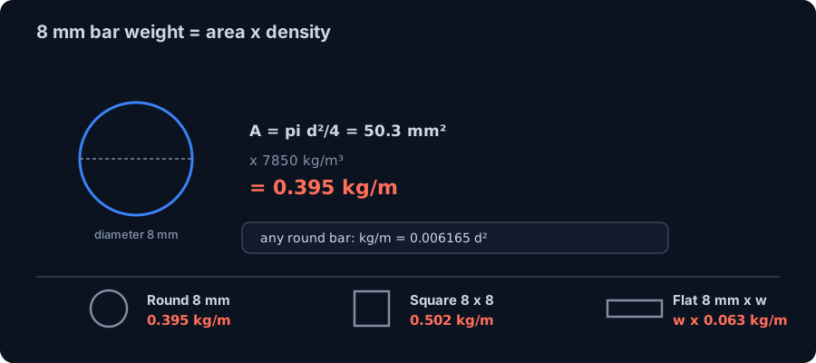
- An 8 mm round steel bar weighs 0.395 kg/m: its area is A = pi d squared / 4 = 50.3 mm squared, and mass is just area times density, kg/m = 0.006165 d squared = A times 0.00785. A square 8 x 8 bar is 0.502 kg/m; a flat bar is width times thickness times 0.00785.
- Weight is the take-off, not the design. To use an 8 mm bar as a structural tie you size it end to end: geometry, load cases, the governing combination, then the tension check.
- On a worked 6 m tied A-frame the CalcSteel engine returns a tie force that matches hand statics to within 0.002 kN with zero bending, and the governing combination 1.2D + 1.6S puts 13.2 kN into the tie, while wind uplift unloads it to slack.
- An 8 mm MR250 bar resists only 11.3 kN in tension (phi Fy Ag), so against the 13.2 kN demand it is at utilisation 1.17 and fails. Weight said nothing about this; the governing load case did.
- Two levers fix it, and neither costs meaningful weight: step to a 10 mm bar (17.7 kN, utilisation 0.75, +0.22 kg/m) or keep 8 mm in a high-strength rod (an A193 B7 rod carries 24.3 kN at the same 0.395 kg/m). Never pick a tie by its weight.
The weight is the easy half of the question
Type peso barra 8mm, or 8 mm bar weight, into any search box and you want one number. Here it is, up front: a plain 8 mm round steel bar weighs 0.395 kg/m. That figure settles the invoice, the truck load and the dead load you feed back into analysis, and the next section derives it from first principles so you never have to trust a table blindly again.
But if the bar is going to carry load, as a tie rod, a sag rod, a bracing rod or a collar tie, the weight is the easy half of the question. The half that actually decides the bar is: is 8 mm strong enough? And that has no answer until you know the force the bar has to carry, which comes from a structure, a set of load cases, and the one combination that governs. A bar you would happily size for its weight can be a bar that fails, and the only way to tell them apart is to size it end to end.
So this article does both. It answers the weight in one line and shows exactly where 0.395 kg/m comes from, then it takes a real 6 m tied frame, drops it into the CalcSteel finite element engine for dead, snow and wind, finds the governing load case, and checks whether the 8 mm bar holds. It does not. The gap between the trivial weight and the failing check is the whole point.
Where 0.395 kg/m comes from, and the other bar shapes
A steel bar's weight per metre is nothing more than its cross-sectional area times the density of steel. There is no catalogue magic and no allowance for shape beyond the area itself:
weight (kg/m) = A (m squared) x 7850 kg/m cubed
For a round bar the area is A = pi d squared / 4, so for d = 8 mm that is A = pi x 8 squared / 4 = 50.3 mm squared. Multiplying by density, 50.3 x 10 to the minus 6 x 7850 = 0.395 kg/m. Fold the constants together and you get the pocket formula for any round bar: kg/m = 0.006165 d squared, with d in millimetres, or equivalently kg/m = A(mm squared) x 0.00785. That single expression reproduces every round-bar weight table there is.
The shape only changes how you get the area:
| 8 mm bar | Area | Weight | Formula |
|---|---|---|---|
| Round, diameter 8 mm | 50.3 mm squared | 0.395 kg/m | pi d squared / 4 x 0.00785 |
| Square, 8 x 8 mm | 64.0 mm squared | 0.502 kg/m | a squared x 0.00785 |
| Flat, 8 mm thick x width w | 8 w mm squared | 0.063 w kg/m | w x t x 0.00785 |
So a 25 x 8 flat bar is 25 x 8 x 0.00785 = 1.57 kg/m, and a 50 x 8 flat bar is 3.14 kg/m. One note that saves confusion later: the 0.395 kg/m of a round 8 mm structural bar is the same number you will find quoted for an 8 mm reinforcing bar, because both are the same steel circle, and a deformed rebar's nominal mass is defined from its plain-round equivalent (see our rebar weight guide). The difference is not the weight, it is the job: rebar is buried in concrete and resists tension through bond, while the bar in this article stands alone as a structural member and has to be sized on its own. For rolled sections rather than bars, the same area-times-density logic drives our profile weight guide and the structural steel weight take-off.
Weigh any bar: the live calculator
Before we turn the bar into a structural member, get the weight side under your fingers. The CalcSteel steel weight calculator is embedded right here, free and with no login: pick a shape, set the dimensions and the length, and it returns the area, the kg/m and the total mass. Enter a round bar at 8 mm and watch 0.395 kg/m appear, then compare a 10 mm and a 12 mm bar so the numbers in the sizing sections below are already familiar.
It runs entirely in your browser. If it opens in its own tab, here is the direct link to the steel weight calculator. Everything past this point is about the other half of the question, the half a weight calculator cannot answer: whether the bar you just weighed is strong enough.
Selected profile
This page ships 1,320 mill-catalog sections offline. The full CalcSteel database — 1,300+ profiles including NBR 6355 cold-formed — lives in the profile database and the 3D editor.
Nominal vs. rolling tolerance — W150x13
Permitted delivered-mass band per product standard. Invoices settle on the nominal kg/m; the band is what an incoming-inspection scale may legitimately read.
W = kg/m × L × n = 13 kg/m × 6 m × 1 = 78 kg
Total weight
78 kg
Unit weight
13 kg/m
Every input above — profile, dimensions, cut list, price — travels in the link.
A tie is sized by force, not by weight
An 8 mm bar rarely appears in a structure as dead weight to be counted. It appears as a tension member: a tie rod that holds two members from spreading, a sag rod that carries the down-slope pull of purlins, a bracing rod in a wall or roof panel, a collar tie across a pitched roof. In every one of those roles its job is to carry an axial pull, and the question that decides it is not how much it weighs but how much it can pull before it yields or tears.
Sizing that bar is a five-step chain, and it is the same chain whether the member is an 8 mm rod or a heavy chord:
- Geometry. Where the bar sits, how long it is, what angle it makes.
- Load cases. The separate actions the structure sees: dead, live or snow, wind.
- Combinations. The factored mixes the code asks you to check.
- The governing case. The single combination that puts the worst force in this bar.
- The capacity check. The bar's tension resistance against that worst force.
Skip to step five with a weight in hand and you are guessing. The next sections walk the whole chain on one concrete bar, and the surprise is at the end: the governing case, not the weight, is what fails the 8 mm section.
The worked structure: a 6 m tied frame
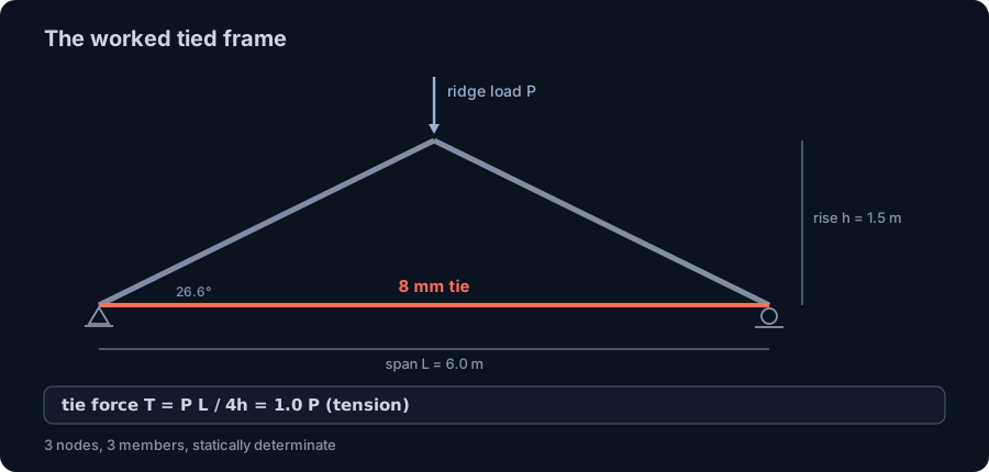
Here is the bar we carry through the rest of the article. It is the horizontal tie of a light tied frame: two rafters meeting at a ridge, with a round bar across the bottom holding the feet from spreading. The frame spans L = 6.0 m between supports and rises h = 1.5 m to the ridge, a rafter slope of about 26.6 degrees and a rafter length of 3.354 m. Frames are spaced 2.0 m on centre, so each one carries a 2.0 m wide strip of a light roof, about 12 m squared.
Count the pieces: three nodes, three members, three reactions (a pin at one foot, a vertical roller at the other). Members plus reactions equal twice the nodes, so the frame is statically determinate: the member forces follow from equilibrium alone, independent of the section sizes. That is exactly why it is a good teaching structure, and why the engine result can be checked by hand to the last digit.
The mechanics of a tied frame are the reason the tie exists. Push down on the ridge and the rafters try to flatten, driving their feet apart. With no horizontal reaction at the supports (one is a roller), the only thing resisting that spread is the tie, which goes into tension. For this geometry the tie force is a clean fraction of the applied ridge load: T = P x L / (4h) = P x 6.0 / (4 x 1.5) = 1.0 P. The tie carries a pull equal to the ridge load itself. Now we just have to find the worst ridge load.
Three load cases, and a hand check to the third decimal
Three actions reach this roof, and they do not act at full value together, so we keep them separate and combine them afterward. Over the 2.0 m frame spacing and the 12 m squared tributary, each is delivered to the ridge as a single load:
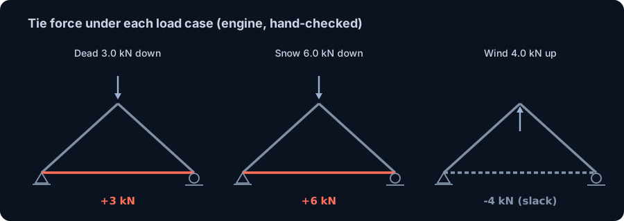
- Dead load D, the light sheeting, purlins and the frame itself, about 0.25 kN/m squared, giving 3.0 kN down at the ridge.
- Snow or roof live load S, about 0.50 kN/m squared, giving 6.0 kN down.
- Wind load W, which on a low-slope roof is dominated by suction, a net uplift of about 0.33 kN/m squared, giving 4.0 kN up, the only case that lifts.
Drop the frame into the CalcSteel engine, run each case, and read the axial force in the tie. Because T = 1.0 P, the numbers are easy to predict and easy to trust:
| Load case | Ridge load | Tie force (engine) | Hand check T = 1.0 P |
|---|---|---|---|
| Dead D | 3.0 kN down | +2.999 kN (tension) | +3.000 kN |
| Snow S | 6.0 kN down | +5.999 kN (tension) | +6.000 kN |
| Wind W | 4.0 kN up | -3.999 kN (compression) | -4.000 kN |
The engine matches hand statics to within 0.002 kN, with the tie's bending under 0.0001 kN.m, confirming it acts as a pure two-force member exactly as a determinate frame should. Two things in that table matter for the design. First, gravity (D and S) pulls the tie in tension, its natural sense. Second, wind uplift pushes it into compression, which for a slender round bar means it simply goes slack: a rod cannot push. Hold on to that. It changes which combinations can load the bar at all.
The combination that governs the tie
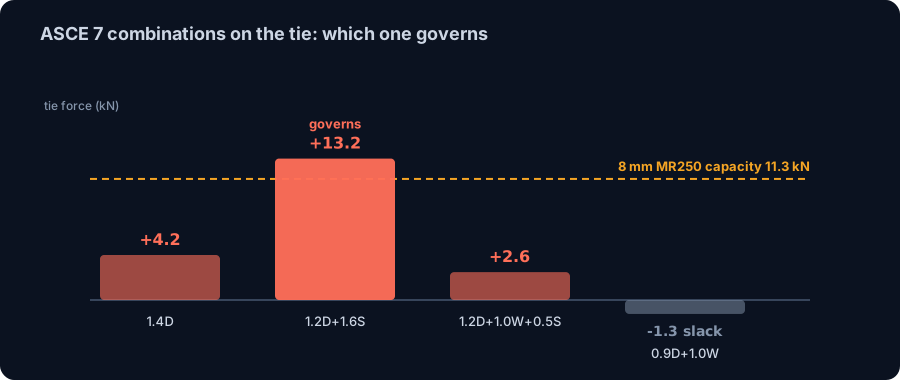
Single cases do not size a member; factored combinations do. Following ASCE 7, four strength combinations matter for this roof. Apply the factors to the tie forces above, remembering that the wind term is negative (it unloads the tie):
| Combination | Tie force | Note |
|---|---|---|
| 1.4D | +4.2 kN | dead only |
| 1.2D + 1.6S | +13.2 kN | governs |
| 1.2D + 1.0W + 0.5S | +2.6 kN | wind trims it |
| 0.9D + 1.0W | -1.3 kN | slack (uplift) |
The governing case is 1.2D + 1.6S = 13.2 kN of tension, and it is worth seeing why the others lose. The dead-only case is small. The two combinations that include wind are the ones a roof designer instinctively fears, but for this bar wind is a relief, not a threat: uplift opposes the gravity pull, so the wind combinations give the smallest tie forces, and 0.9D + 1.0W even pushes the tie slack. The case that governs is the plain gravity maximum, the one with no wind in it at all.
That is the first real lesson of sizing end to end. The load case that governs a member is the one that maximises the demand in that member, and it is not always the dramatic one. For a roof tie under gravity it is the snow combination, quietly, while the wind cases that dominate the cladding design barely touch it. The engine forms all four combinations and reports the envelope, so the governing 13.2 kN is computed, not guessed. Different codes land in the same place: Eurocode's 1.35D + 1.5S gives 13.1 kN and Brazil's NBR 8681 gravity combination about 12.6 kN, all within a few percent of the ASCE value. Around 13 kN, then, is the number the bar has to beat.
Does the 8 mm bar pass? The tension check
Now the question the weight could not answer. The tie has to carry 13.2 kN. What can an 8 mm bar resist? A tension member is checked two ways, and the smaller answer governs.
Yielding on the gross section. The bar must not stretch permanently along its length. In MR250 steel (yield Fy = 250 MPa, the default Brazilian structural grade, equivalent to ASTM A36), the design tension resistance is
phi Fy Ag = 0.90 x 250 x 50.3 = 11,310 N = 11.3 kN.
Rupture on the effective net area. Wherever the bar is threaded or holed, the reduced area must not tear. A plain welded 8 mm bar keeps its full area, so rupture (phi = 0.75, phi Fu Ag = 0.75 x 400 x 50.3 = 15.1 kN) does not govern. But most tie rods are threaded into a turnbuckle or a clevis, and threading cuts the area. The AISC threaded-rod rule (Fnt = 0.75 Fu on the nominal area) gives phi x 0.75 Fu x Ag = 0.75 x 0.75 x 400 x 50.3 = 11.3 kN, the same value as gross yielding for this steel.
So an 8 mm MR250 bar resists about 11.3 kN, whether you check it as a plain yielding bar or as a threaded rod. Against the governing demand:
utilisation = 13.2 / 11.3 = 1.17.
The 8 mm bar is at 117 percent of its capacity. It fails, and it fails by a margin no factor of safety forgives. Read that against the weight: the bar that weighs a trivial 0.395 kg/m is not a bar you can use here, and nothing about its weight told you so. Only sizing it against the governing load case did.
Two ways to fix it, neither about weight
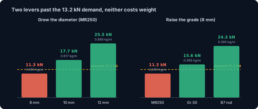
A member at utilisation 1.17 needs more capacity. For a tension bar there are exactly two levers, and the striking thing is that neither one costs meaningful weight.
Lever one: a bigger diameter. Tension capacity scales with area, and area scales with the square of the diameter, so a small step in diameter buys a large step in strength:
| Bar | Area | Capacity (MR250) | Utilisation at 13.2 kN | Weight |
|---|---|---|---|---|
| 8 mm | 50.3 mm squared | 11.3 kN | 1.17 (fails) | 0.395 kg/m |
| 10 mm | 78.5 mm squared | 17.7 kN | 0.75 | 0.617 kg/m |
| 12 mm | 113 mm squared | 25.5 kN | 0.52 | 0.888 kg/m |
Stepping to a 10 mm bar takes the utilisation to 0.75, comfortably passing. The weight goes from 0.395 to 0.617 kg/m, an extra 0.22 kg/m, which over the 6 m tie is about 1.3 kg more steel on the whole frame. That is the entire cost of turning a failing member into a safe one.
Lever two: a stronger steel, same 8 mm. If the detail or the geometry pins you to 8 mm, raise the grade instead. A plain welded bar in Grade 50 / A572 (Fy = 345 MPa) resists 15.6 kN, utilisation 0.85, and passes. If the rod is threaded, Grade 50 only reaches 12.7 kN and still fails narrowly, so go to a genuine high-strength rod: an ASTM A193 B7 rod (Fu = 860 MPa) carries 24.3 kN even threaded, utilisation 0.54, at exactly the same 0.395 kg/m. Double the capacity, identical weight.
Both levers make the same point from opposite directions: the weight of a tie is almost irrelevant to whether it works. You do not save anything real by under-sizing it, and you do not spend anything real by sizing it right. Pick the bar for the governing force, never for its weight.
The bar-specific catch: slenderness and sag
A round bar has one property that no wide-flange shares: it is astonishingly slender. Its radius of gyration is r = d / 4, so for an 8 mm bar r is just 2.0 mm. Over the 6 m tie that is a slenderness of L / r = 6000 / 2 = 3000, a number that would be absurd for any compression member (codes cap those at KL/r = 200).
In tension that slenderness is not a strength problem. Both AISC 360 and NBR 8800 recommend keeping tension members under L/r of about 300 as good practice, but both explicitly exempt rods and cables, precisely because a rod is far too slender to meet it and does not need to: a straight pull does not buckle. What the slenderness does affect is serviceability. A 6 m rod hanging under its own weight sags visibly, and a slack rod (remember the uplift case) sags freely with nothing to straighten it. That is why real tie rods are pretensioned, fitted with a turnbuckle to take up the slack, or given an intermediate support.
The numbers are reassuring once the rod is doing its job. Under the service tension of roughly 9 kN (the unfactored dead plus snow pull), the self-weight sag of the 6 m bar is only about w L squared / (8 T) = 0.0039 x 36 / (8 x 9) = 2 mm, invisible in practice. The lesson is not that sag governs, it is that a bar is not a beam: you size it for the governing tension, then take a moment to make sure the code's rod exemption applies and that the detail controls the sag. The engine flags a member whose slenderness leaves the ordinary range, so the exemption is a decision you make, not one you forget.
Same bar, different job, different governing case
It is tempting to conclude that gravity always governs a tie. It does not. What governs depends on what the bar does, and the cleanest way to see it is to give the very same 8 mm bar a different job.
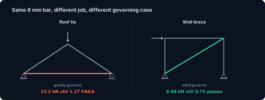
Put it in a light bracing panel: a 3.0 m by 3.0 m bay with the round bar as a diagonal, resisting the lateral wind shear on the wall. The diagonal sits at 45 degrees, so a story shear V pulls it with T = V / cos 45 = 1.414 V. Take a wind shear of 6.0 kN: the CalcSteel engine returns a diagonal force of 8.48 kN, matching V / cos 45 = 8.49 kN to the second decimal. Under gravity this brace carries essentially nothing, there is no lateral load to resist, so its governing case is wind, the exact opposite of the tie.
| The same 8 mm bar as... | Governing case | Design force | On MR250 (11.3 kN) |
|---|---|---|---|
| Roof tie (holds the rafters) | 1.2D + 1.6S (gravity) | 13.2 kN | utilisation 1.17, fails |
| Wall brace (resists wind) | wind shear | 8.48 kN | utilisation 0.75, passes |
One bar, one weight, one cross-section, two completely different verdicts, because the governing load case is different for each role. This is why a weight lookup can never stand in for a design: 0.395 kg/m is true in both rows and decides neither. The force that governs, found by running the load cases for the structure the bar actually lives in, is the only thing that tells you whether 8 mm is a sensible tie or a failed one.
What the codes ask, on three continents
The workflow, load cases then combinations then a tension check, is the same everywhere; only the packaging differs. For a tie rod the relevant clauses are:
- United States (ASCE 7 + AISC 360). ASCE 7 supplies the LRFD combinations, including the 1.2D + 1.6S gravity maximum that governs here. AISC 360 Chapter D checks tension: yielding on the gross section (phi = 0.90 on Fy Ag) and rupture on the effective net area (phi = 0.75 on Fu Ae), with threaded rods handled through Chapter J3.6. The L/r of 300 guidance in D1 is a recommendation and expressly excludes rods.
- Europe (EN 1990 + EN 1993-1-1). EN 1990 builds the combinations with partial factors, roughly 1.35G + 1.5Q for the gravity case, here 13.1 kN. EN 1993-1-1 clause 6.2.3 checks the tension resistance Nt,Rd as the lesser of the gross-section plastic resistance A fy / gammaM0 and the net-section ultimate resistance 0.9 Anet fu / gammaM2.
- Brazil (NBR 8800 + NBR 8681). NBR 8681 sets the combinacoes ultimas, giving about 12.6 kN for the gravity case. NBR 8800 checks tracao as the smaller of escoamento da secao bruta (Ag fy / gamma-a1) and ruptura da secao liquida (An fu / gamma-a2), and its lambda of 300 recommendation for tension members, like the others, exempts rods.
Different symbols, one idea: whichever code you use hands you a gravity combination near 13 kN and a tension resistance near 11 kN for an 8 mm MR250 bar, and the verdict is the same on all three continents. The CalcSteel engine checks the member against AISC 360, Eurocode 3 and NBR 8800 from the same forces, so the governing case and the failing utilisation are found for you rather than remembered.
Common mistakes and FAQ
"An 8 mm bar weighs almost nothing, so it is fine here." Weight and strength are unrelated for a tie. The 0.395 kg/m bar failed the governing case at utilisation 1.17. Size for the force, then read the weight off as a consequence.
"Wind uplift governs the roof, so it governs the tie." Not for a bottom tie. Uplift opposes the gravity pull and unloads the tie, even pushing it slack. The governing case here is 1.2D + 1.6S, with no wind in it. Which case governs is a per-member question.
"It is a tie, just check the gross-section yield." Only if the bar is plain and welded. A threaded rod tears on its reduced area first, and the AISC threaded-rod check lands at the same 11.3 kN as yielding for A36, so you cannot skip it.
"The bar is 6 m long and hopelessly slender, so it is no good." In tension the slenderness is a serviceability matter, not a strength one, and codes exempt rods from the L/r limit. Pretension it or add a turnbuckle to control sag and the straight pull is fine.
How much does an 8 mm steel bar weigh?
A round 8 mm bar weighs 0.395 kg/m (area 50.3 mm squared times density 7850 kg/m cubed). A square 8 x 8 bar is 0.502 kg/m, and a flat bar 8 mm thick is width x 8 x 0.00785 kg/m.
Is an 8 mm bar strong enough for a tie?
It depends entirely on the governing load case. An 8 mm MR250 bar resists about 11.3 kN in tension. On the worked frame here the governing demand is 13.2 kN, so 8 mm fails and a 10 mm bar is needed; on a lighter frame or a wind brace the same bar can pass. There is no weight-based answer, only a force-based one.
What is the difference between an 8 mm structural bar and 8 mm rebar?
The weight is identical, 0.395 kg/m, because both are the same 8 mm steel circle. The difference is the job: rebar is embedded in concrete and develops its force through bond, while a structural bar stands alone as a tie and is sized on its own tension capacity.
How do I make an 8 mm tie work if the demand is too high?
Either increase the diameter (a 10 mm bar nearly doubles the capacity to 17.7 kN for +0.22 kg/m) or raise the steel grade at the same 8 mm (an A193 B7 rod reaches 24.3 kN at the same 0.395 kg/m). Both add negligible weight.
From a weight to a sized tie
You came for a weight and you have it: an 8 mm round steel bar weighs 0.395 kg/m, and every round-bar weight is just kg/m = 0.006165 d squared. But the weight was the easy half. The moment the bar has to carry load, the deciding number is the force in the governing load case, and on the worked frame that number, 13.2 kN of gravity tension, is one the 8 mm bar cannot hold.
The chain that told us so is worth keeping: geometry, load cases, combinations, the governing case, the tension check. The CalcSteel engine walked it end to end, matching hand statics on the tie to within 0.002 kN, forming the combinations, and returning the utilisation of 1.17 that a weight lookup would never have flagged. Fixing it cost almost no weight, a 10 mm bar or a stronger rod, which is the whole moral: a tie is chosen by the force that governs it, not by the kilograms it adds.
Size your own bar the same way. Model the frame in the CalcSteel editor, add the load cases, and let the engine find the governing combination and the tension check on every member at once, free and in your browser. When you need the combinations themselves, our guide to load combinations lays out the factors, and the roof truss worked example shows the same governing-case logic drive a whole set of members. Students get everything unlocked through CalcSteel Education, free.
Sources
- 1.ANSI/AISC 360, Specification for Structural Steel Buildings (Chapter D, tension members; J3.6, threaded rods)
- 2.ASCE/SEI 7, Minimum Design Loads and Associated Criteria for Buildings and Other Structures (LRFD load combinations)
- 3.EN 1993-1-1, Eurocode 3: Design of steel structures, Part 1-1 (clause 6.2.3, tension), and EN 1990, Basis of structural design
- 4.ABNT NBR 8800, Projeto de estruturas de aco de edificios, and NBR 8681, Acoes e seguranca nas estruturas
- 5.AISC Design Guide 1 and the AISC Manual Part 15 (rods, tie rods and connecting elements)
Try CalcSteel for free
Model, analyze and design steel structures in your browser. No install, no signup.
Open the 3D editor