Integral Calculus on a Real Structure: the Seven Integrals Inside One Warehouse Frame
Integral calculus is not one trick you use once and file away. On a single ordinary job it gets evaluated at least seven times, in seven different roles, and almost every number the client actually reads is the value of an integral: the tonnage on the quotation, the wind force and the height it acts at, the moment in a purlin, the stiffness of a section, the sway the drift limit judges, the square metres the painter invoices. This article takes one 20 m span portal frame warehouse and evaluates all seven on it, each checked against a published table, a closed form, or a second independent method on the CalcSteel finite element engine.
Key takeaways
- Seven integrals, one job. On this warehouse the tonnage is ∫ρ dV, the wind resultant is ∫p(z) dA, the shear and moment are ∫w dx and ∫V dx, the section properties are ∫dA, ∫y dA and ∫y² dA, the stress field has to satisfy ∫σ dA = N, the sway is ∫Mm/EI ds and the painted surface is ∮ds. Not one of them is optional.
- The wind integral is the one most often skipped, and it fails in two directions at once. Taking the pressure at mid height instead of integrating it gives 30.408 kN against the true 28.797 kN, 5.59 % too much force, while the base moment comes out 106.43 kN·m against 113.94 kN·m, 6.59 % too little. Too much load, applied too low.
- The resultant of a power law pressure acts at z̄ = H(n+1)/(n+2), not at mid height. For this 7.0 m wall that is 3.957 m, 13.0 % higher than the 3.5 m everyone assumes, and the overturning moment is what sizes the holding down bolts.
- Banding the wall does not rescue it. Two bands are 17.80 % out on the force, four bands 10.15 %, seven bands, one per metre, still 6.31 %. The exact integral costs one line of algebra: F = k·b·H^(n+1)/(n+1).
- The sway of the whole frame is a single integral evaluated over four members. ∫Mm/EI ds + ∫Nn/EA ds returns 11.57778 mm against the 11.57705 mm the solver's stiffness matrix reports, a difference of 0.0063 %. Two methods that share nothing but the model.
- That integral also tells you what to stiffen. 41.58 % of the sway accumulates in the windward column and 30.98 % in the leeward one, so 72.56 % lives in the columns and only 27.44 % in the rafters. Bending is 99.823 % of the total and axial shortening 0.177 %.
- An integral is only as good as the data under the integral sign. The same frame solved with a second moment of area 4.62 % below the published table sways 3.78 % more. The section table is not a formality, it is an input to every one of the seven.
One warehouse, and every question the client asks is an integral
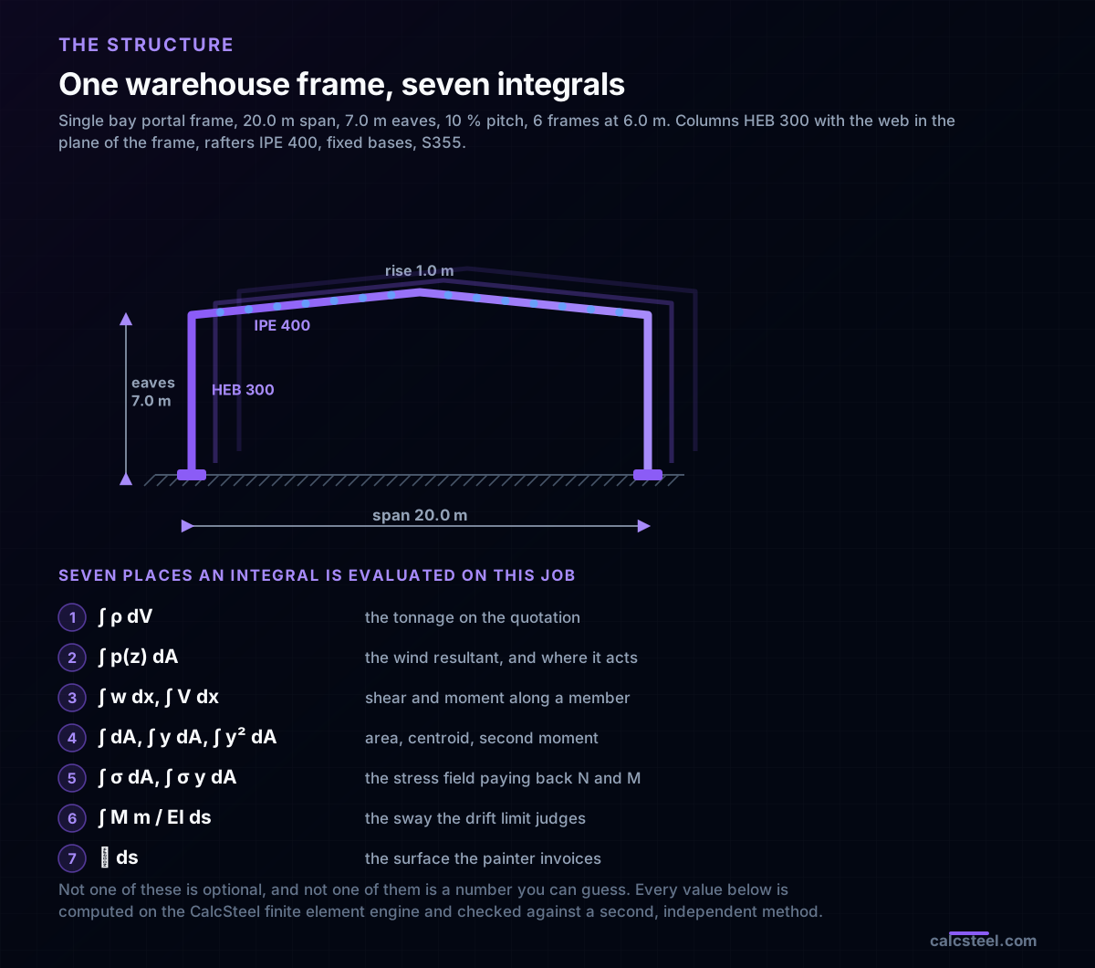
A client wants a 20 m by 30 m shed. Clear span, 7 m to the eaves, a 10 % roof pitch, six portal frames at 6 m centres. Columns HEB 300, rafters IPE 400, S355, fixed bases. It is the most ordinary steel building there is, and it will be designed several thousand times this year.
The client asks four questions. How much steel is that. Will it stand up in the wind. Will the doors still shut when it blows. What will the painting cost.
Every one of those four answers is the value of an integral, and so is every intermediate quantity between the question and the answer. Not by analogy, and not in the loose sense that calculus underlies engineering. Literally: the number you write on the sheet is what you get when you integrate something.
This article walks the job in the order it actually happens and evaluates each of them, on the same building, with the same section data. Seven integrals. Every value below was computed on the CalcSteel finite element engine or integrated in closed form, and every one is checked against something independent: the published EN 10365 section table, a hand derivation, or a second solution method.
What an integral is once you leave the exam hall
The definition you were taught is the area under a curve. It is correct, and it is the least useful way to hold the idea on a real job, because almost nothing you integrate on a structure is drawn as a curve on a page.
The working definition is shorter. An integral is what you do when a quantity varies and you need its total. If it did not vary you would multiply. Pressure times area. Mass per metre times length. Because it varies, you multiply over a slice small enough that it does not vary inside the slice, then add up the slices, then take the slices to zero. That last step is the whole of the machinery, and it is why the answer is exact rather than approximately right.
Two consequences run through everything below.
The first is that an integral gives you more than a total. The same machinery with an extra factor inside gives you where the total acts. ∫p dA is the force; ∫z p dA divided by ∫p dA is the height it acts at. That second integral, the first moment, is the one people skip, and it is the one that decides the foundation.
The second is that skipping an integral is never free, only sometimes cheap. Every shortcut in this article is a replacement of an integral by a single multiplication, and every one of them has a measurable error that is quoted to two decimal places further down. Some are worth 0.06 %. One is worth 17.80 %.
Integral 1: the tonnage on the quotation is ∫ρ dV
Start with the question the client asks first, because it is the one that decides whether you get the job. How much steel.
Mass is a volume integral, m = ∫ρ dV. Steel is homogeneous, so ρ comes out of the integral and you are left with the volume, and the volume of a prismatic member is itself an integral along its axis: V = ∫A ds. The cross-sectional area A is constant along a rolled member, so this collapses to A times length and you get the familiar kilograms per metre. That collapse is the reason the section table exists at all: somebody already did the integral for you and printed the answer.
Check that the printed answer is the integral. Integrating the IPE 400 cross section, fillets included, gives A = 84.58 cm², and 84.58 cm² times 7 850 kg/m³ is 66.39 kg/m against the 66.3 kg/m in the table, 0.14 % apart. The HEB 300 gives 117.03 kg/m against 117.0. The table is the integral.
Now run the job. Each frame has 14.0 m of column, two 7.0 m lengths, and 20.10 m of rafter, because the sloping rafter is √(10² + 1²) = 10.04988 m long, not 10 m. That extra 49.9 mm per rafter is the kind of thing that vanishes in a hurry and reappears on delivery.
- Columns: 14.0 m × 117.03 kg/m = 1 638.4 kg
- Rafters: 20.10 m × 66.39 kg/m = 1 334.5 kg
- One frame: 2 972.9 kg
- Six frames: 17.837 tonnes, or 29.73 kg per square metre of floor
That 29.73 kg/m² is the number an estimator carries in their head, and it is a volume integral wearing ordinary clothes. Note what it excludes: purlins, side rails, bracing, base plates, bolts. The frames alone are typically a little under half the delivered tonnage of a shed like this.
Integral 2: the wind resultant, and the height it acts at
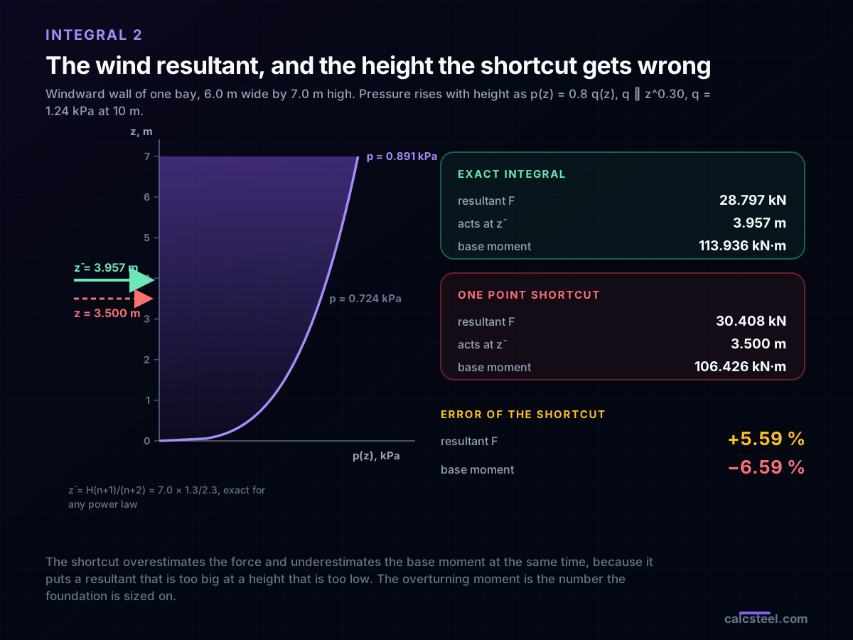
Wind pressure is not uniform up a wall. It rises with height, because the wind speed does. NBR 6123 models that rise with a power law through its S2 factor, and EN 1991-1-4 uses a logarithmic profile that behaves much the same way over this height range. Take the power law form for open country, so the dynamic pressure goes as z^0.30, with a reference pressure of 1.24 kPa at 10 m and a windward external pressure coefficient of 0.8:
p(z) = 0.8 × 1.24 × (z/10)^0.30 kPa
At the top of a 7 m wall that is 0.891 kPa. At mid height it is 0.724 kPa. At knee height it is under half of the top value. The pressure varies, so the total is an integral, over the 6.0 m wide by 7.0 m high panel of one bay:
F = ∫₀^H p(z) b dz = k·b·H^(n+1)/(n+1), with k = 0.8 q/10^n and n = 0.30
That is a power rule, first week of Calculus I, and it gives F = 28.797 kN on the bay. A numerical integration over 200 000 strips returns the same value to twelve significant figures, which is the closed form checking itself.
The second integral is the one that matters more, and it is the one that usually does not get written down. Where does that 28.797 kN act? Take moments about the base of the wall as you integrate:
z̄ = ∫ z p(z) b dz / ∫ p(z) b dz = H(n+1)/(n+2)
For any power law that ratio is exact and independent of the pressure magnitude. Here z̄ = 7.0 × 1.3/2.3 = 3.957 m. Not 3.5 m. The resultant sits 13.0 % higher up the wall than mid height, and the base moment is 113.936 kN·m per bay.
What the one point shortcut costs, measured
Nobody sets out to skip the integral. What happens is that someone reads the pressure at mid height off a table, multiplies by the wall area, and moves on. It looks defensible, it is fast, and here is what it costs.
0.724 kPa × 7.0 m × 6.0 m = 30.408 kN, against the true 28.797 kN. That is 5.59 % too much force, and being on the high side, it feels safe. Then the same shortcut puts that force at 3.5 m, so the base moment becomes 106.43 kN·m against the true 113.94 kN·m, which is 6.59 % too little. Too much load, applied too low.
The overturning moment is the number the base plate, the holding down bolts and the footing are sized on. The shortcut is unconservative in exactly the place where being wrong is expensive, and it is conservative in the place where being wrong costs almost nothing, because a portal frame column is rarely governed by shear. That is the worst possible pairing, and it is a direct consequence of the shortcut throwing away the first moment integral.
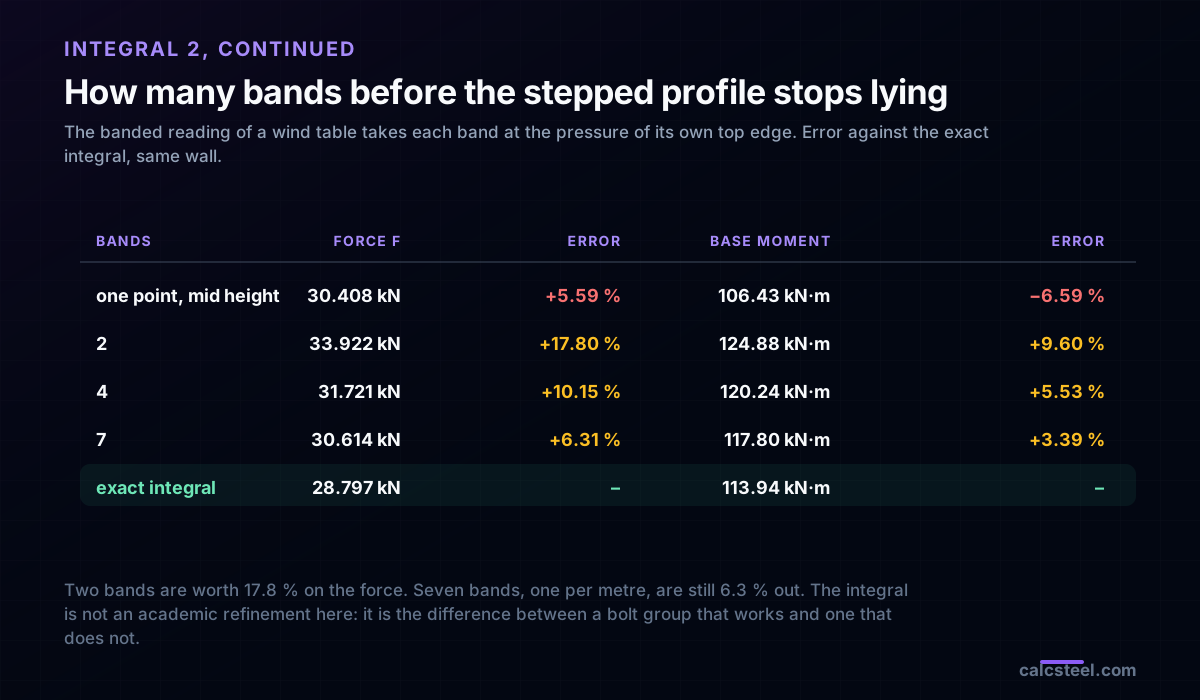
The obvious fix is to band the wall. Read the pressure at the top of each band, apply it to that band, sum. It is the rectangle rule from numerical integration, and it converges, slowly:
- 2 bands: F is 17.80 % high, base moment 9.60 % high
- 4 bands: F is 10.15 % high, base moment 5.53 % high
- 7 bands, one per metre: F is still 6.31 % high, base moment 3.39 % high
Seven bands is more work than the integral and it is still 6 % out. Applying the varying pressure element by element along a 40 element column, which is what the analysis model below actually does, reproduces the closed form to 0.058 %. Fine discretisation converges; coarse banding does not.
None of this makes the codes wrong. Code bands are drawn deliberately on the conservative side of the pressure, and they carry partial factors on top. The point is narrower and more useful: you do not know which way a banded answer errs, or by how much, unless you have the integral to compare it with.
Integral 3: integrate the load once for shear, twice for moment
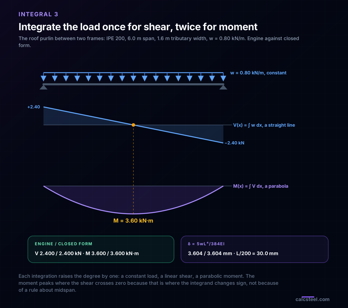
The wind load reaches the frame through the sheeting and the purlins, so take a purlin next. IPE 200, spanning the 6.0 m between two frames, carrying a 1.6 m strip of roof. Dead plus imposed at 0.50 kN/m² gives w = 0.80 kN/m, uniform.
The two relationships every structural engineer uses daily are differential, and reading them the other way round makes them integrals:
dV/dx = −w, so V(x) = V₀ − ∫w dx
dM/dx = V, so M(x) = ∫V dx
The bending moment at a section is the signed area under the shear diagram up to that section. Each integration raises the degree by one: a constant load gives a linear shear gives a parabolic moment. Integrate a constant and you get a ramp; integrate a ramp and you get a parabola. The shapes of the diagrams you have drawn since your first year are not conventions, they are the degrees coming out of the integrations.
On the purlin: V at the support is wL/2 = 2.400 kN, the engine returns 2.400 kN. The moment at midspan is wL²/8 = 3.600 kN·m, the engine returns 3.600 kN·m. Integrate twice more, against EI, and the midspan deflection is 5wL⁴/384EI = 3.604 mm; the engine returns 3.604 mm, against an L/200 limit of 30.0 mm.
The moment peaks at midspan here, and the reason is worth stating precisely, because the wrong reason is widespread. It peaks where the shear crosses zero. The shear is the integrand of the moment, so where the integrand changes sign the accumulated area stops growing and starts shrinking. On a symmetric simply supported span that happens at midspan. Move the load off centre, or add a cantilever, and the zero of the shear moves, and the maximum moment moves with it. Midspan is a coincidence of this load case, not a rule.
Integral 4: four integrals over the same cut
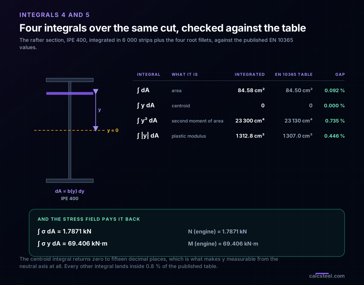
The moment is now known. To turn it into a stress you need the shape of the section, and every property that describes that shape is an integral over the same cut. Four of them, each with a different weight inside.
- A = ∫dA. Weight nothing. How much steel is there.
- Q = ∫y dA. Weight by distance. Zero when y is measured from the centroid, and that is the definition of the centroid rather than a coincidence.
- I = ∫y² dA. Weight by distance squared. How far the steel sits from the axis, which is what bending stiffness is.
- Z = ∫|y| dA. Weight by absolute distance. The plastic modulus, the fully yielded version of the same idea.
Integrating the real IPE 400 in 6 000 horizontal strips, plus the four root fillets treated as lumps of area r²(1 − π/4) at 0.2234 r off the flange face, gives A = 84.58 cm² against 84.50 in the table, I = 23 300 cm⁴ against 23 130, and Z = 1 312.8 cm³ against 1 307.0. Every one inside 0.8 %. The centroid integral returns zero to fifteen decimal places, which is what licenses you to measure y from the neutral axis in the first place.
The squared weight in I is the whole reason an I beam is shaped like an I. The two flanges of this section are 193 mm from the axis and the web is spread across everything nearer than that. Move steel outward and its contribution grows with the square, which is why a deep light section beats a shallow heavy one, and why the parallel axis theorem, I = I₀ + Ad², is not a separate rule but what falls out of expanding (y + d)² inside the same integral.
Integral 5: the stress field has to pay back N and M
Integrals 3 and 4 meet here, and the meeting is a test rather than a step.
The analysis gives internal forces at a section: at the base of the windward column under wind, N = 1.787 kN and M = 69.406 kN·m. The section gives a stress distribution: σ(y) = N/A + M y / I. Those two came from completely different places, so nothing yet guarantees they are consistent. Equilibrium demands that they are, and equilibrium is stated as two integrals:
∫σ dA = N and ∫σ y dA = M
Integrate the assumed stress field over the real section and you get 1.7871 kN and 69.406 kN·m. They match, to fourteen decimal places on the axial term and exactly on the moment. That is not a lucky result, it is the definition of what N and M mean: they are not forces that exist alongside the stresses, they are the first two integrals of the stress field. A distribution that does not integrate back to the analysis forces is not that member's stress field, whatever else it might be.
The section modulus falls straight out. If σ is linear in y then ∫σ y dA = (σ_max/c) ∫y² dA = σ_max I / c, so M = σ_max × I/c and the familiar W = I/c is nothing more than the second integral divided by the distance to the extreme fibre. Push the section to full yield instead, so that σ = ±f_y everywhere, and the same integral becomes ∫f_y|y| dA = f_y Z. Elastic and plastic bending are not two theories. They are the same integral over two different stress fields.
For this HEB 300 in S355 that gives an elastic moment of 600.2 kN·m and a plastic moment of 666.1 kN·m, a shape factor of 1.110. Against them, the 69.4 kN·m at the base runs the extreme fibre to 41.17 MPa, a utilisation of 0.116. This frame is nowhere near its bending capacity, which is normal for a shed of this size and tells you immediately where to look next.
Integral 6: the sway is one integral over the whole frame
If strength is at 12 %, the frame will be governed by stiffness, and the client's third question, will the doors still shut, is a deflection question. This is the integral the whole article has been walking towards, because it is the one that runs over the entire structure at once rather than over one section or one member.
The unit load method says: to find the deflection at a point in a chosen direction, apply a unit load there, get the internal forces m and n it produces, and integrate their product with the real internal forces M and N over every member of the structure.
δ = ∫ M m / EI ds + ∫ N n / EA ds
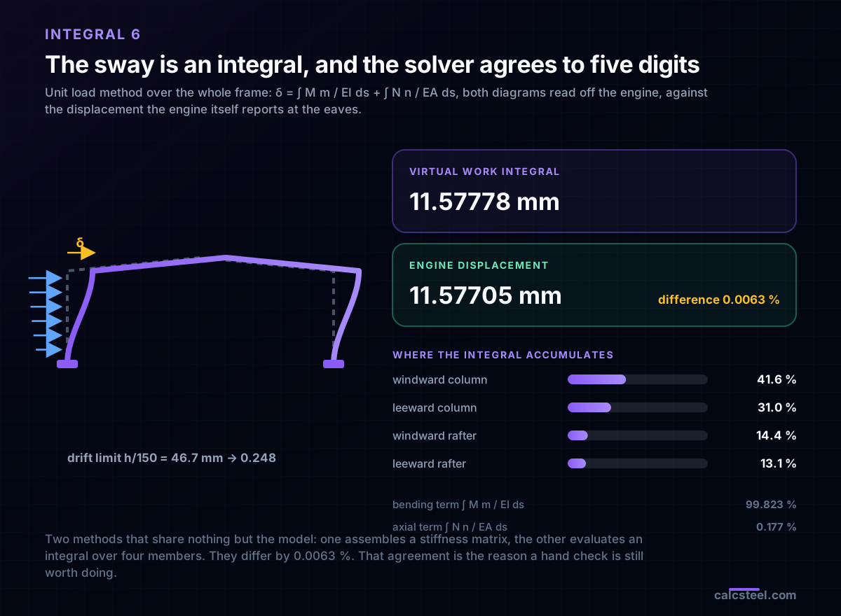
The ds runs along the members, all four of them, including up and over the pitched rafters where ds is longer than the horizontal projection. Both diagrams here were read off the engine, one run with the real wind pressure and one with a 1 kN horizontal load at the eaves, and the product was integrated element by element in closed form.
The integral returns 11.57778 mm. The engine, which never evaluates that integral and instead assembles and inverts a stiffness matrix, reports 11.57705 mm at the same node. They differ by 0.0063 %.
Two methods that share nothing but the model and the section data. One is a matrix solve, the other is calculus over four members that you could do on paper in an afternoon. Agreement at the fifth significant figure is the reason a hand check on an analysis is still worth doing: it is not a slower way of getting the same answer, it is an independent route to it.
Against an eaves drift limit of h/150 = 46.67 mm, 11.58 mm is a utilisation of 0.248. The doors will shut.
The integral also tells you what to stiffen
A single number out of a solver tells you whether you passed. The integral tells you why, because you can stop it partway and ask where the total came from. Split the same 11.578 mm by member:
- Windward column: 41.58 %
- Leeward column: 30.98 %
- Windward rafter: 14.37 %
- Leeward rafter: 13.06 %
72.56 % of the sway accumulates in the two columns and 27.44 % in the rafters. If this frame had failed its drift check, deepening the rafter would have bought you at most a quarter of the improvement per kilogram that deepening the columns would. That is a design decision read directly out of an integrand, and no single displacement number contains it.
The split between the two terms is worth a look too. The bending term ∫Mm/EI ds is 99.823 % of the total and the axial term ∫Nn/EA ds is 0.177 %. For a frame of ordinary proportions axial shortening is genuinely negligible, which is why every textbook drops it. It stops being negligible in tall braced frames and in trusses, where the members are loaded axially by design and the bending term is the small one.
There is no shear term in this integral, and that is a deliberate match to the solver rather than an omission. The engine here is Euler-Bernoulli: a cantilever column under a tip load returns 116.75937 mm against the F h³/3EI value of 116.75937 mm, agreeing to nine significant figures, which is only possible if shear deformation is absent. Adding a Timoshenko shear term would have contributed 1.309 mm on that cantilever, 1.12 %. Real, small, and not what this model contains.
One more result from the same integral, and it is the one to take away. Solve the frame again with a second moment of area 4.62 % below the published table value, exactly the sort of gap between a rounded section database and EN 10365, and the sway comes out 3.78 % larger. The integral is exact. Its answer is only as good as the ∫y² dA you feed it, and that number came from integral 4, three sections ago. The seven are not independent.
Try it: integrate a span yourself
The purlin above is the cleanest of the seven to run by hand and to check. Set the span to 6.0 m and a uniform load of 0.80 kN/m and you should get a support shear of 2.400 kN, a midspan moment of 3.600 kN·m and a deflection of 3.604 mm. Then move the load off centre and watch the zero of the shear move, and the peak of the moment move with it.
Change the section and watch the moment stay exactly where it is while the deflection changes. The moment is the second integral of the load and knows nothing about the steel; the deflection is the fourth, and EI enters at the third. Statics before stiffness, and you can see the boundary between them here.
Max moment
45 kN·m
Max shear
30 kN
Max deflection
10.55 mm
= L/569
Bending stress σ
84.4 MPa
σ = M/Sx
Utilization
44.0%
NBR 8800 · δ ≤ L/250
Geometry & supports
Section
Ix 7999 cm⁴ · Sx 533 cm³ · 42.2 kg/m
Point loads (↓ positive)
None — add as many as you need.
Distributed loads (uniform or trapezoidal)
Model sketch
Diagrams — free PNG / SVG / CSV export, no watermark
Step-by-step — the calculation memory of YOUR beam
IPE 300 · L = 6 m · fy = 250 MPa
1. Reactions (equilibrium of the solved FEM model)
ΣFy = 0 · ΣM = 0
R_A = 30 kN · R_B = 30 kN
2. Peak shear (read from the SFD)
Vmax = |V(x)|max
Vmax = -30 kN @ x = 6 m
3. Peak moment (read from the BMD)
Mmax = |M(x)|max
Mmax = 45 kN·m @ x = 3 m
4. Peak deflection
EI = 15998 kN·m² (E = 200 GPa)
δmax = 10.55 mm @ x = 3 m = L/569
5. Elastic bending stress
σ = Mmax / Sx = 45.00 × 10³ / 533.3
σ = 84.4 MPa
6. Bending check — both codes, side by side
NBR 8800: σ ≤ fy/1.10 = 227.3 MPa · AISC 360: σ ≤ 0.90·fy = 225 MPa
NBR 37.1% PASS · AISC 37.5% PASS
7. Deflection check (serviceability — code-independent)
δ ≤ L/250 = 24 mm
10.55 mm / 24 mm = 44.0% PASS
Recomputed live from the current inputs by the direct-stiffness FEM engine — change any load and every step updates. Reproduce it by hand with the formulas in the sections below.
Lightest catalog profiles that pass (974 flexural candidates · NBR 8800)
| Profile | Std | Weight | Total steel | σ util | δ util | |
|---|---|---|---|---|---|---|
| W310x21 | AISC | 21 kg/m | 126 kg | 83% | 98% | |
| VS 300x23 | BR | 22.6 kg/m | 136 kg | 71% | 84% | |
| U 300x90x6.3 | BR | 23.1 kg/m | 139 kg | 82% | 98% | |
| U 300x100x6.3 | BR | 24.1 kg/m | 145 kg | 77% | 91% | |
| VS 250x25 | BR | 24.6 kg/m | 148 kg | 70% | 100% |
Elastic bending (σ = M/Sx vs fy/γa1, γa1 = 1.10 — NBR 8800) + deflection screening of the full flexural catalog. Lateral-torsional buckling, shear and local buckling are NOT checked here — run the full NBR 8800 / AISC 360 verification in the 3D editor.
Integral 7: the last one goes on the invoice
The client's fourth question was the painting, and the answer is a contour integral. The painted surface of a member is the closed path around its cross section, ∮ds, multiplied by the length.
Walk the outline of an I section with square corners and you get 4b + 2h − 2t_w. For the IPE 400 that is 4(180) + 2(400) − 2(8.6) = 1 502.8 mm. But the corners are not square, they are quarter round fillets of radius r, and each one replaces a path of 2r by an arc of πr/2. Four of them remove 4(2r − πr/2) = 36.05 mm, giving 1 466.7 mm, or 1.4667 m²/m. The published value is 1.467 m²/m. The integral agrees to 0.02 %.
Those fillets are 2.4 % of the perimeter. Ignore them and every metre of every member on the job is overstated by 2.4 %, which is small until you multiply it by the whole building and compare it with a coating quotation.
Running the job: 14.0 m of HEB 300 at 1.732 m²/m is 24.2 m², 20.10 m of IPE 400 at 1.467 m²/m is 29.5 m², so 53.7 m² per frame and 322.3 m² for the six. That is 18.07 m² of surface per tonne of steel, and the ratio is the reason light sections cost more to protect than their tonnage suggests.
The same contour integral has a second life in fire design. The section factor A_m/V, the heated perimeter divided by the volume per metre, is 116.2 m⁻¹ for the HEB 300 and 173.4 m⁻¹ for the IPE 400. The rafter heats roughly half as fast again as the column under the same fire, from the same two integrals: the contour on top and the area underneath.

Six ways the integral gets dropped, and what each one costs
Every one of these has a number attached, measured on the building above.
- Replacing a varying pressure by its mid height value. 5.59 % too much force and 6.59 % too little base moment, at the same time. The sign of the error is different on the two quantities, so no single safety factor covers both.
- Forgetting the first moment integral. The resultant of a power law acts at H(n+1)/(n+2), which for this wall is 3.957 m rather than 3.5 m. Everything downstream of the base moment, the base plate, the anchors, the footing, inherits the error.
- Trusting a coarse banding. Seven bands over 7 m is more arithmetic than the closed form and is still 6.31 % out. If you are going to discretise, discretise properly or integrate.
- Assuming the maximum moment is at midspan. It is at the zero of the shear, because the shear is the integrand. On this purlin the two coincide; change the load and they part company.
- Measuring the rafter horizontally. ds along a 10 % pitch is 10.04988 m, not 10 m, in the mass integral, in the paint integral and in the deflection integral. 0.5 % on every rafter quantity in the job.
- Feeding the integral rounded section data. A second moment of area 4.62 % below the table changes the computed sway by 3.78 %. The integral cannot be more accurate than what is under the integral sign.
The whole job, in one line
Seven integrals, one shed, and the chain runs end to end without a gap. ∫ρ dV priced it. ∫p dA loaded it and ∫z p dA decided where. ∫w dx and ∫V dx carried the load down a purlin. ∫dA, ∫y dA and ∫y² dA described the shape that resists it. ∫σ dA and ∫σ y dA proved the stresses and the forces are the same object seen twice. ∫Mm/EI ds answered whether the doors shut, and told you which member to fix if they did not. ∮ds went on the invoice.
The reason to know this is not that you will evaluate them by hand. You will not; the software will, several thousand times, in the second after you press Calculate. The reason is that the software is only running the integrals you set up, over the geometry you drew and the sections you chose, and every one of the seven has a place where it can be quietly fed the wrong thing. A pressure read at one point. A rafter measured flat. A section modulus from a rounded table.
The engineer who knows which integral is being evaluated at each step knows where to look when a number comes back wrong. That is the whole return on Calculus I and II, and it arrives on the first real job rather than in the exam.
Sources
- 1.EN 1991-1-4, Eurocode 1: Actions on structures, part 1-4: wind actions. The height varying velocity pressure profile and the external pressure coefficients used for the windward wall
- 2.ABNT NBR 6123, Forças devidas ao vento em edificações. The S2 factor and its power law form q(z) ∝ z^(2p)
- 3.EN 1993-1-1, Eurocode 3: Design of steel structures, part 1-1. Elastic and plastic section moduli, and serviceability deflection limits
- 4.EN 10365 and Euronorm 19-57, dimensions and properties of hot rolled I and H sections. The published A, Ix, Wel, Wpl, kg/m and Am for IPE 200, IPE 400 and HEB 300, used as the external anchor for every integrated value here
- 5.AISC 360, Specification for Structural Steel Buildings, and the AISC Steel Construction Manual section property tables
- 6.Hibbeler, Structural Analysis (the unit load method, ∫Mm/EI dx, and its application to frames)
- 7.Gere and Goodno, Mechanics of Materials (first and second moments of area, the parallel axis theorem, and the load, shear and moment relations)
- 8.Timoshenko and Young, Theory of Structures (virtual work and the Euler-Bernoulli against Timoshenko treatment of shear deformation)
- 9.EN 1993-1-2, Eurocode 3 part 1-2: structural fire design. The section factor Am/V as heated perimeter over volume per unit length
Try CalcSteel for free
Model, analyze and design steel structures in your browser. No install, no signup.
Open the 3D editor