Free Body Diagrams: Draw One Step by Step
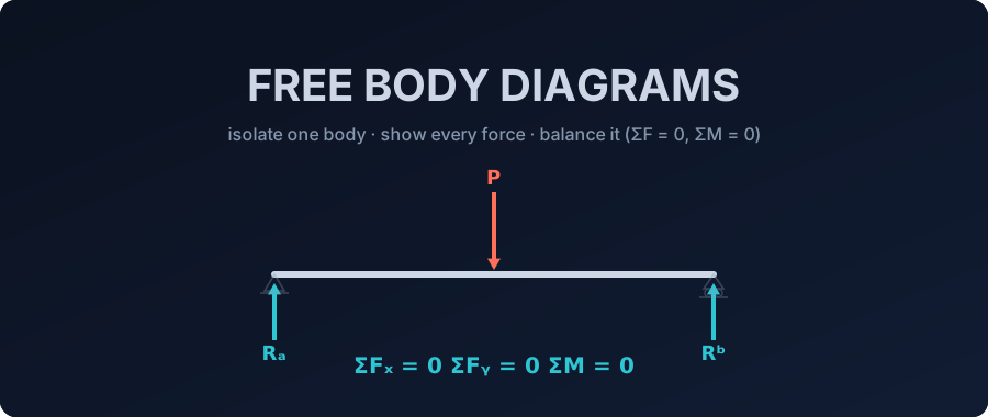
Learn what a free body diagram is and how to draw one step by step to solve reactions and equilibrium equations. Try the free live beam calculator.
Key takeaways
- A free body diagram isolates one body and shows every external force and moment acting on it - applied loads, self-weight, and reactions - and nothing internal.
- Isolate a whole beam to find its reactions: for L = 8 m with P = 40 kN at 3 m, R_A = 25 kN and R_B = 15 kN, matched by the CalcSteel engine.
- A distributed load enters the free body diagram as its resultant — W = w·L at the centroid — for reactions only: 15 kN/m over 6 m acts like 90 kN at midspan (R = 45 kN each side), but internal forces must come from the real distribution.
- Cut the body and keep one piece to expose internal forces: at x = 2 m, V = 25 kN and M = 50 kN·m; at x = 5 m, V = -15 kN and M = 45 kN·m.
- A truss-joint diagram uses only the two force equations (ΣFx = 0 and ΣFy = 0) because every member force is concurrent at the pin.
- Wrapping a whole frame in one free body still balances every load exactly - ΣFy = 120 kN, ΣFx = -20 kN - even when the interior is statically indeterminate.
Free body diagrams - from a single beam to a whole steel frame
Every reaction you solve for, every shear and moment diagram you plot, every member force in a truss, every base plate you size — all of it secretly starts with the same drawing: a free body diagram. It is the sketch you make when you mentally cut a body free from the world and draw every force acting on it. Get that picture right and the equilibrium equations almost solve themselves. Get it wrong and every number downstream is wrong too.
This guide walks the free body diagram all the way up the ladder of structural analysis. We start by isolating a single beam to find its reactions, then we cut the beam open to expose its internal shear and moment, then we zoom into one joint of a truss to read off member forces, and finally we wrap a whole steel portal frame in one free body to see how its reactions must balance every applied load — even when the frame is too complex to solve by hand.
Two readers will get value here. If you are a statics student, this is the first-year staple laid out cleanly, with a live calculator to check your work. If you are a practicing engineer, it is a tight refresher on the one idea that connects your hand checks to what a FEM solver does at every node. Every number in this article was computed by CalcSteel's real FEM engine and hand-verified against a free body diagram to three decimals — nothing here is invented, and you can reproduce all of it in the browser for free.
What a free body diagram actually is
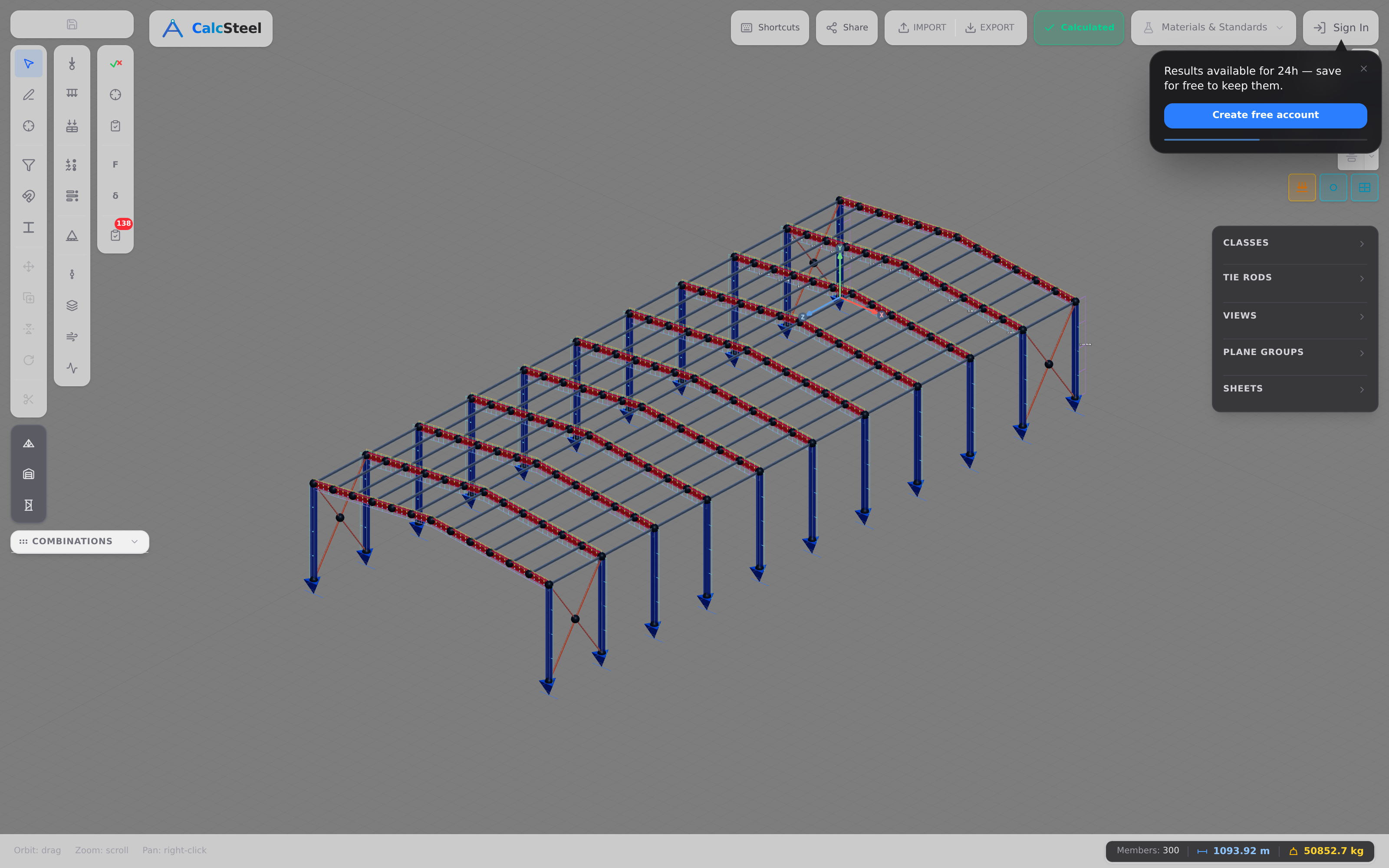
A free body diagram is a sketch of one body isolated — cut free — from everything around it, showing every external force and moment acting on it: the applied loads, the body's self-weight, and the reaction forces that supports and neighbouring members exert on it. It shows those forces and nothing else. That is the whole definition, and its power is in the word nothing: once a body is cut free, the surrounding structure disappears and is replaced entirely by the forces it used to transmit.
Why bother drawing it? Because it is the only reliable way to set up the equilibrium equations. A body that is not accelerating obeys ΣFx = 0, ΣFy = 0 and ΣM = 0 — but those sums only make sense once you have a clear inventory of the forces to add up. The free body diagram is that inventory.
The central trick is that supports are replaced by the forces they produce. A pin does not appear on the diagram; the horizontal and vertical reactions it can push back with appear in its place. A fixed base does not appear; its two reaction forces plus a reaction moment appear instead. We give the full support-to-reaction dictionary a few sections down, but the mindset starts here: draw the body alone, then let every place you cut it speak for itself with a force.
Where the free body diagram came from
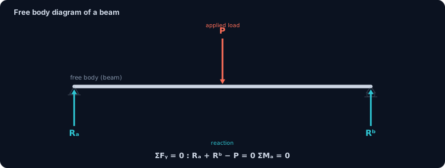
The idea of isolating a body and balancing the forces on it is roughly two thousand years old. Archimedes (~250 BC) gave us the law of the lever and the statics of moments — the first rigorous statement that a body balances when opposing turning effects cancel. Much later, Simon Stevin (1586) showed how forces combine geometrically through the force triangle and the parallelogram of forces, the seed of graphical analysis.
The decisive leap was Isaac Newton's Principia (1687) and its three laws. The second and third laws are precisely what license the free body diagram: because forces come in equal-and-opposite pairs, you are allowed to remove a support and stand in its place a single reaction force. Pierre Varignon (1725) added his theorem of moments — the moment of a resultant equals the sum of the moments of its components — which is what makes ΣM = 0 practical to compute.
Then Leonhard Euler (~1750) wrote down the equations of rigid-body equilibrium, ΣF = 0 and ΣM = 0, and formalised the cut principle — the Euler cut — that makes internal forces explicit by slicing a body open. Jean le Rond d'Alembert (1743) extended equilibrium into dynamics with his principle, and Karl Culmann (1866) built graphic statics into a full drawing-based method for force diagrams. The modern, named free body diagram as a teaching device crystallised in early-twentieth-century engineering-mechanics texts — notably Stephen Timoshenko's statics teaching in the 1930s.
The lineage matters because the physics has not changed. The isolate-and-balance idea Archimedes started is exactly what CalcSteel's FEM engine performs today — enforcing the same equilibrium at every node of a structure, in milliseconds, in your browser.
How to draw a free body diagram (5 steps)
Almost every free body diagram, from a first-year beam to a full steel frame, follows the same five-step recipe. Learn it once and it never changes — only the body you point it at does.
- Decide which body to isolate. It might be the whole structure, one member, a cut piece of a member, or a single joint. This choice is the whole game: pick the body that exposes the unknown you want.
- Draw that body alone. Redraw it cut free from every support and every neighbouring member, floating on the page with nothing else touching it.
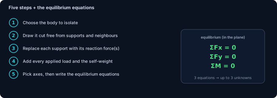
- Replace each cut with the force(s) it can exert. Wherever you severed a support or a contact, draw in the reaction it produces — this is the support-to-reaction dictionary of the next section. A roller gives one force, a pin two, a fixed base two forces and a moment.
- Add every applied load and the self-weight at its correct point and direction. For unknown reactions, just assume a direction — if you guessed wrong, the algebra hands you a negative number and corrects you.
- Fix a coordinate system and sign convention, then write the equilibrium equations. With axes and signs pinned down, the diagram becomes arithmetic.
For a planar (2D) body those equilibrium equations are exactly three:
- ΣFx = 0 — horizontal forces balance;
- ΣFy = 0 — vertical forces balance;
- ΣM = 0 — moments about any point balance.
Three equations means you can solve for up to three unknowns per body. If the free body has more unknown reactions or member forces than that, it is statically indeterminate — the equilibrium equations alone are not enough, and you need a stiffness or finite-element method (exactly what CalcSteel runs) to pin down the extras. Finally, remember Newton's third law: when you cut a body in two, the internal force appears equal and opposite on the two pieces either side of the cut — the same magnitude, pointing opposite ways, so the pieces would slot back together in perfect balance.
Supports and the reactions they produce
Every free body diagram lives or dies on one step: when you cut a body free from its supports, you have to replace each support with the exact force system it was silently applying. Get this dictionary right and the equilibrium equations almost write themselves. Get it wrong — a forgotten moment, a phantom horizontal force — and every number downstream is corrupt.
The logic is beautifully simple: a support supplies one reaction for each movement it prevents. If a support stops a body from translating in a direction, it must be able to push or pull in that direction — that is a reaction force. If it stops the body from rotating, it must be able to apply a moment — that is a reaction moment. Count the restrained degrees of freedom and you have counted the reactions.
Here is the dictionary every planar free body diagram needs:
- Roller → 1 reaction. It stops translation perpendicular to its surface only. One force, perpendicular to the rolling surface. It cannot resist motion along the surface and cannot resist rotation.
- Pin / hinge → 2 reactions. It stops translation in both in-plane directions but freely allows rotation. Two forces — a horizontal H and a vertical V — and no moment. This is why a pin is a “two-force” support and why truss members meeting at a pin carry no bending.
- Fixed / built-in → 3 reactions. It clamps the body completely: no horizontal slide, no vertical slide, no rotation. Two forces (H and V) plus a reaction moment M. A cantilever's built-in end embedded in a wall, or a welded column base, is a fixed support.
- Cable / link → 1 reaction. A flexible cable can only pull, along its own line — one tension force directed away from the body, along the cable axis. A rigid two-force link is the same idea but may also push.
Notice the pattern in the count: a roller restrains 1 degree of freedom → 1 reaction; a pin restrains 2 → 2 reactions; a fixed support restrains all 3 → 3 reactions. In a plane you have exactly three equilibrium equations per body (ΣFx = 0, ΣFy = 0, ΣM = 0), so you can solve up to three unknown reactions on a single free body. A simply-supported beam (one pin + one roller) has 2 + 1 = 3 unknowns and is exactly solvable by hand — you will see that in the next section. A frame with two fixed bases has 3 + 3 = 6 reaction unknowns against only 3 global equations: it is statically indeterminate, and only a stiffness / FEM approach recovers the individual reactions.
This dictionary is not a teaching abstraction — it is precisely what CalcSteel's supports encode. When you drop a pin, roller, or fixed base onto a node in the editor, you are telling the FEM engine which degrees of freedom to restrain, and the solver answers with exactly the reaction components listed above. The free body diagram you would draw by hand and the boundary conditions the engine assembles are the same object.
Worked example 1: the free body diagram of a beam (find the reactions)
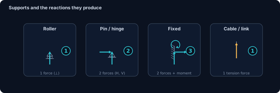
Time to turn the recipe into numbers. Take the classic case: a simply-supported beam of span L = 8 m, with a pin at A (x = 0) and a roller at B (x = 8 m), carrying a single downward point load P = 40 kN at a = 3 m from A. We want the support reactions — and the free body diagram is the only tool we need.
Step 1 — isolate the whole beam. The body we choose is the entire beam, cut free from both supports. We draw it alone, floating in space.
Step 2 — replace each support with its reactions. From the dictionary above: the pin at A gives two reactions, but with no horizontal load the horizontal component is zero, so we draw a vertical reaction RA pointing up. The roller at B gives one vertical reaction RB, also pointing up. The applied load P = 40 kN points down at x = 3 m. That is the complete free body diagram: two unknown upward forces, one known downward force.
Step 3 — write the equilibrium equations. With two unknowns we need two equations. Take moments about A first, because RA passes through A and drops out, leaving a single unknown:
- ΣMA = 0: RB · 8 − 40 · 3 = 0 → RB · 8 = 120 → RB = 15 kN.
- ΣFy = 0: RA + RB − 40 = 0 → RA = 40 − 15 = 25 kN.
Step 4 — check. Total up = 25 + 15 = 40 kN; total down = 40 kN. ΣFy = 0 balances exactly, and the load sits closer to A, so the nearer support A carrying the larger share (25 kN vs 15 kN) passes the sanity test. Both reactions came out positive, so our assumed “upward” directions were right.
This is the calibration case for everything that follows. Fed the identical model, CalcSteel's FEM engine returned RA = 25.0 kN and RB = 15.0 kN, with the vertical reactions summing to 40 kN — matching the hand free body diagram to three decimals. The point is not that a computer can add; it is that the engine is doing exactly what your pencil did, node by node, and agreeing exactly.
Want the theory behind these numbers, or to skip straight to the answer for your own beam? See how beam reaction forces work, then drop your span and loads into the free beam reaction calculator.
Worked example 2: the free body diagram of a distributed load
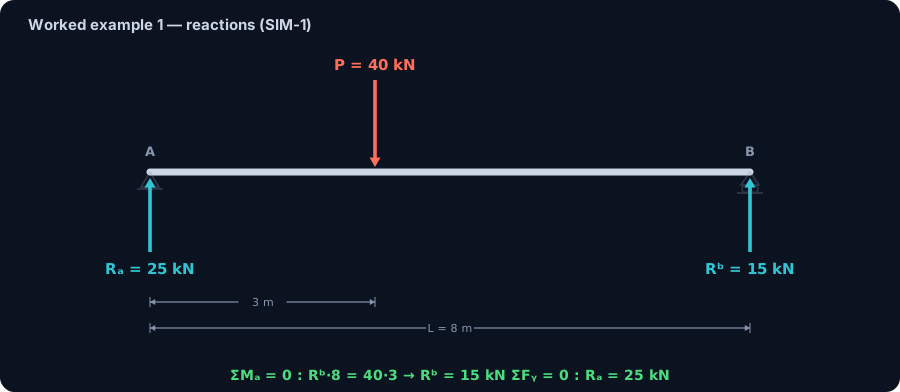
Real beams rarely carry a single tidy point load — floor joists, purlins and bridge girders pick up load spread along their whole length. Take a simply-supported beam of span L = 6 m, with a pin at A, a roller at B and a uniformly distributed load w = 15 kN/m over the full span. How does a load with no single point of application go on a free body diagram?
The resultant trick. For the equilibrium of the body as a whole, a distributed load may be replaced by its resultant: one force equal to the area of the load diagram, acting through its centroid. Here W = w · L = 15 · 6 = 90 kN, acting at the centroid of the rectangle — midspan, x = 3 m. The free body diagram collapses into something we already know how to solve: two unknown reactions and one known 90 kN force.
- ΣMA = 0: RB · 6 − 90 · 3 = 0 → RB = 45 kN.
- ΣFy = 0: RA = 90 − 45 = 45 kN.
By symmetry both reactions come out at 45 kN — and CalcSteel’s FEM engine, fed the actual distributed load rather than the shortcut, returns exactly 45 kN at each support, matching the hand calculation to three decimals.
The fine print — where the trick stops working. The resultant is only equivalent for the external equilibrium of the free body you drew. The moment you cut the beam to expose internal forces — the move the method of sections below turns into a recipe — you must go back to the real distribution and take the resultant of only the load on the piece you kept. Cut at x = 2 m: the kept piece carries RA = 45 kN up and 15 · 2 = 30 kN of load, so V = 45 − 30 = 15 kN and M = 45 · 2 − 30 · 1 = 60 kN·m — the 30 kN acts 1 m from the cut, at the centroid of the loaded 2 m, not at midspan of the whole beam. Use the whole-beam resultant here and you would get 90 kN·m, 50% too high. The engine confirms the correct values: V = 15 kN and M = 60 kN·m at x = 2 m, with the peak moment wL²/8 = 67.5 kN·m at midspan.
Draw your own: the live beam calculator
Reading about a free body diagram is one thing; watching the reactions move as you drag a load is another. The calculator embedded right here is the free body diagram of Example 1, made live — so put it to work.
Start by recreating our worked case: set the span to 8 m and place a 40 kN point load 3 m from the left support. The reactions resolve to 25 kN and 15 kN — the same two numbers we found by hand and the same two the FEM engine returned. That agreement is the whole point: the picture you would sketch on paper and the result on screen are one and the same equilibrium.
Now experiment. Slide the load toward the right support and watch the near reaction grow while the far one shrinks; centre it and watch the two split evenly at 20 kN each; add a second load and watch both reactions absorb it. Every move is a fresh free body diagram being solved instantly — you are building the intuition that ΣFy and ΣMA encode, without touching the algebra.
It is unlimited and completely free, with no login required for the math — that is the proof, not a countdown timer. When you are ready to move beyond a single beam to a full frame with real profiles and code checks, the same engine is waiting in the beam calculator and the full editor.
Then go one step further: delete the point load, add a distributed load of 15 kN/m on a 6 m span, and watch both reactions settle at 45 kN — worked example 2 live, resultant and all.
Max moment
45 kN·m
Max shear
30 kN
Max deflection
10.55 mm
= L/569
Bending stress σ
84.4 MPa
σ = M/Sx
Utilization
44.0%
NBR 8800 · δ ≤ L/250
Geometry & supports
Section
Ix 7999 cm⁴ · Sx 533 cm³ · 42.2 kg/m
Point loads (↓ positive)
None — add as many as you need.
Distributed loads (uniform or trapezoidal)
Model sketch
Diagrams — free PNG / SVG / CSV export, no watermark
Step-by-step — the calculation memory of YOUR beam
IPE 300 · L = 6 m · fy = 250 MPa
1. Reactions (equilibrium of the solved FEM model)
ΣFy = 0 · ΣM = 0
R_A = 30 kN · R_B = 30 kN
2. Peak shear (read from the SFD)
Vmax = |V(x)|max
Vmax = -30 kN @ x = 6 m
3. Peak moment (read from the BMD)
Mmax = |M(x)|max
Mmax = 45 kN·m @ x = 3 m
4. Peak deflection
EI = 15998 kN·m² (E = 200 GPa)
δmax = 10.55 mm @ x = 3 m = L/569
5. Elastic bending stress
σ = Mmax / Sx = 45.00 × 10³ / 533.3
σ = 84.4 MPa
6. Bending check — both codes, side by side
NBR 8800: σ ≤ fy/1.10 = 227.3 MPa · AISC 360: σ ≤ 0.90·fy = 225 MPa
NBR 37.1% PASS · AISC 37.5% PASS
7. Deflection check (serviceability — code-independent)
δ ≤ L/250 = 24 mm
10.55 mm / 24 mm = 44.0% PASS
Recomputed live from the current inputs by the direct-stiffness FEM engine — change any load and every step updates. Reproduce it by hand with the formulas in the sections below.
Lightest catalog profiles that pass (974 flexural candidates · NBR 8800)
| Profile | Std | Weight | Total steel | σ util | δ util | |
|---|---|---|---|---|---|---|
| W310x21 | AISC | 21 kg/m | 126 kg | 83% | 98% | |
| VS 300x23 | BR | 22.6 kg/m | 136 kg | 71% | 84% | |
| U 300x90x6.3 | BR | 23.1 kg/m | 139 kg | 82% | 98% | |
| U 300x100x6.3 | BR | 24.1 kg/m | 145 kg | 77% | 91% | |
| VS 250x25 | BR | 24.6 kg/m | 148 kg | 70% | 100% |
Elastic bending (σ = M/Sx vs fy/γa1, γa1 = 1.10 — NBR 8800) + deflection screening of the full flexural catalog. Lateral-torsional buckling, shear and local buckling are NOT checked here — run the full NBR 8800 / AISC 360 verification in the 3D editor.
Cutting the body: internal forces (method of sections)
So far we isolated the whole beam and found what the world does to it: the reactions. But the most powerful move in all of structural analysis is to isolate only part of a body. When you slice a beam through and keep one piece as your free body, that piece is no longer in equilibrium on its own — the material you just cut away used to hold it. To restore balance, the cut face must supply exactly the forces that missing material was carrying. Those forces are the internal forces: the axial force N, the shear V, and the bending moment M at that section.
This is the method of sections, and it is just a free body diagram of a cut piece. Let's use the same simply-supported beam from Worked Example 1 — span L = 8 m, a pin at A, a roller at B, and a downward point load P = 40 kN at 3 m from A — where we already found RA = 25 kN and RB = 15 kN. Now we cut it in two places.
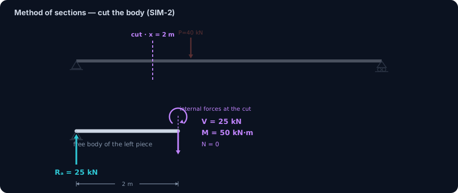
Cut at x = 2 m (to the left of the load). Keep the 0–2 m piece as the free body. The only external force on it is RA = 25 kN pushing up; the load hasn't been reached yet. For this piece to stay still:
- ΣFy = 0 → the cut face must carry a shear V = 25 kN downward to balance RA.
- ΣM at the cut = 0 → the cut face must carry a bending moment M = 25 × 2 = 50 kN·m.
- There is no horizontal load, so the axial force N = 0.
Cut at x = 5 m (to the right of the load). Now the 0–5 m free body has RA = 25 kN up and the full P = 40 kN down. Balancing:
- ΣFy = 0 → V = 25 − 40 = −15 kN (the sign tells you the shear has flipped direction past the load).
- ΣM at the cut = 0 → M = 25 × 5 − 40 × 2 = 45 kN·m.
Here's the beautiful check: you can isolate the other piece instead. Take the right 5–8 m free body, whose only external force is RB = 15 kN. Then M = 15 × 3 = 45 kN·m — identical. Newton's third law guarantees it: whichever side you keep, the cut face carries an equal-and-opposite pair, so both free bodies report the same internal M and V.
We ran this cut through CalcSteel's FEM engine and sampled the internal forces: at x = 2 m, V = 25 kN and M = 50 kN·m; at x = 5 m, V = −15 kN and M = 45 kN·m — exact to three decimals against the hand FBD.
Now the bridge to every diagram you've ever drawn in structural analysis: a shear-force / bending-moment diagram is nothing more than this cut free body diagram evaluated at every section. Slide the cut continuously from x = 0 to x = 8 m, plot V and M at each position, and you have the SFD and BMD. The FBD isn't a warm-up for those diagrams — it is those diagrams, one section at a time. If you want the full treatment of how those curves are built and read, see our companion guide to shear force and bending moment diagrams.
Worked example 3: the free body diagram of a truss joint
A truss changes the target of the free body diagram: instead of isolating a length of beam, you isolate a single pin joint. This is the method of joints, and it exposes a special simplification. Because every member meeting at a pin runs through the joint, all the forces on your free body are concurrent — they share one point. Concurrent forces produce no moment arm about that point, so the moment equation is automatically satisfied and carries no information. A truss-joint FBD therefore uses only ΣFx = 0 and ΣFy = 0 — two equations, no moment equation.
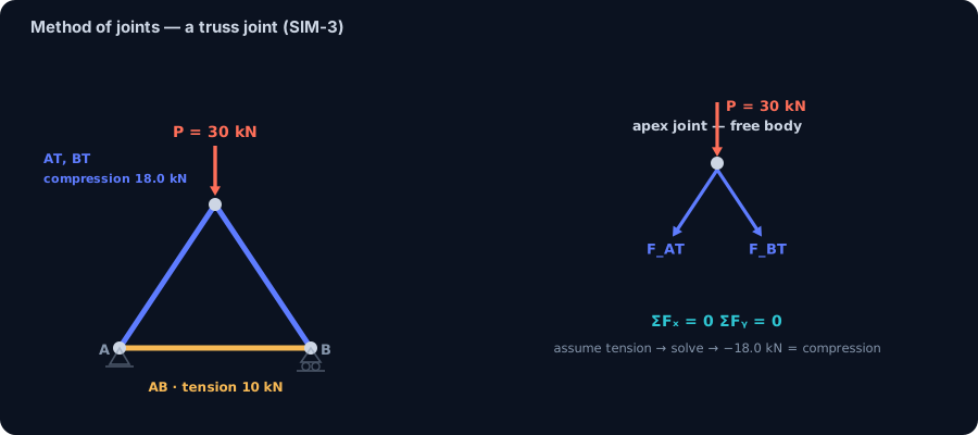
Consider a symmetric triangular truss: a pin support at A(0, 0), a roller at B(4 m, 0), and an apex at T(2 m, 3 m), with a single downward load P = 30 kN hanging at the apex. Each diagonal rises 3 m over a 2 m run, so its angle is θ = atan(3/2) = 56.31°, its length is √13 = 3.606 m, and the trig values are sin θ = 0.832, cos θ = 0.555. By symmetry the reactions are equal: RA = RB = 15 kN.
Apex-joint FBD. Isolate joint T. Two diagonals, AT and BT, and the 30 kN load meet here. The load pulls down; the two diagonals must together push up. By symmetry each carries the same force Fdiag, and only the vertical components resist the load:
- ΣFy = 0 → 2 · Fdiag · sin θ = P → Fdiag = 30 / (2 × 0.832) = 18.03 kN.
- The diagonals push up on the apex, which means they push back against it — both AT and BT are in compression.
Joint-A FBD. Isolate support A. Three forces meet: the reaction RA = 15 kN up, the diagonal AT, and the bottom chord AB running horizontally to B. The horizontal balance fixes the chord:
- ΣFx = 0 → AB = P / (2 · tan θ) = 30 / (2 × 1.5) = 10.0 kN.
- The chord pulls the two supports inward — AB is in tension, exactly as a bottom chord should be.
We modelled the same truss in CalcSteel. The FEM engine returned AT = BT ≈ −18.0 kN (compression) and AB ≈ +9.9 kN (tension) — matching the hand FBD — and reported a negligible member moment of about 0.19 kN·m. That near-zero moment is the whole point: it confirms the members behave as pure two-force members carrying axial force only, which is precisely the assumption the joint FBD is built on. The hand method and the engine agree because they are the same equilibrium.
Want to take this from a three-bar demonstration to a real roof or bracing layout? Our guide to steel truss design walks the whole workflow, and you can build and solve one yourself in the CalcSteel editor.
The climax: the free body diagram of a whole frame
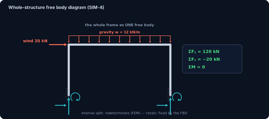
We started by isolating a single beam. Now zoom all the way out and isolate an entire building. Take a fixed-base steel portal frame: a 10 m beam carried on two 5 m columns, both bases built in. Load it the way the wind and gravity really load it — a uniform gravity load of w = 12 kN/m across the 10 m beam (a total of 120 kN down) plus a lateral wind push of H = 20 kN at the top-left corner. Draw one free body: the whole frame, cut free from the ground at both bases, with the reactions replacing what the foundations do.
The reactions of that single free body must balance every applied load, no matter how complicated the structure inside is:
- ΣFy = 0 → the total vertical reaction equals the gravity that came down: 120 kN up.
- ΣFx = 0 → the total horizontal reaction must cancel the wind: −20 kN (20 kN pushing back against the 20 kN push).
- ΣM = 0 → the base moments close the balance.
CalcSteel's engine confirmed the whole-body totals exactly: ΣFy(reactions) = 120.0 kN and ΣFx(reactions) = −20.0 kN. This is the same three equations you used on a single beam — just wrapped around a much bigger body.
Now the lesson that makes this the climax of the whole story. Ask a harder question: how does that 120 kN split between the two bases, and how much horizontal load does each base take? A fixed-base portal frame is statically indeterminate — it has more reaction unknowns than the three equilibrium equations can solve. There is no hand formula for the split. The engine finds it by solving the frame's stiffness: the left base takes about 55.2 kN vertical, the right about 64.8 kN, with nearly all of the horizontal reaction landing at the leeward base. Those numbers require FEM.
And yet — here is the point — the whole-body free body diagram still pins the totals perfectly. Equilibrium doesn't care whether the interior is determinate or not: cut the whole frame free, and its reactions must sum to the applied loads. The FBD gives you the exact totals for free, and hands the interior split to the solver. Hand analysis and FEM are not rivals here; they answer at two different scales of the same picture.
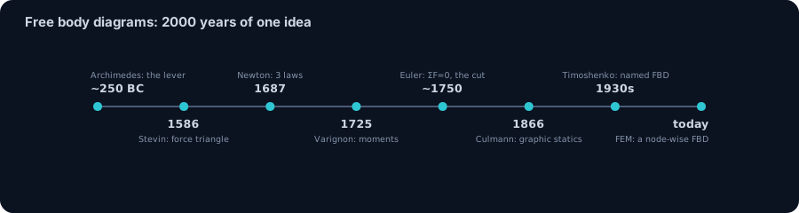
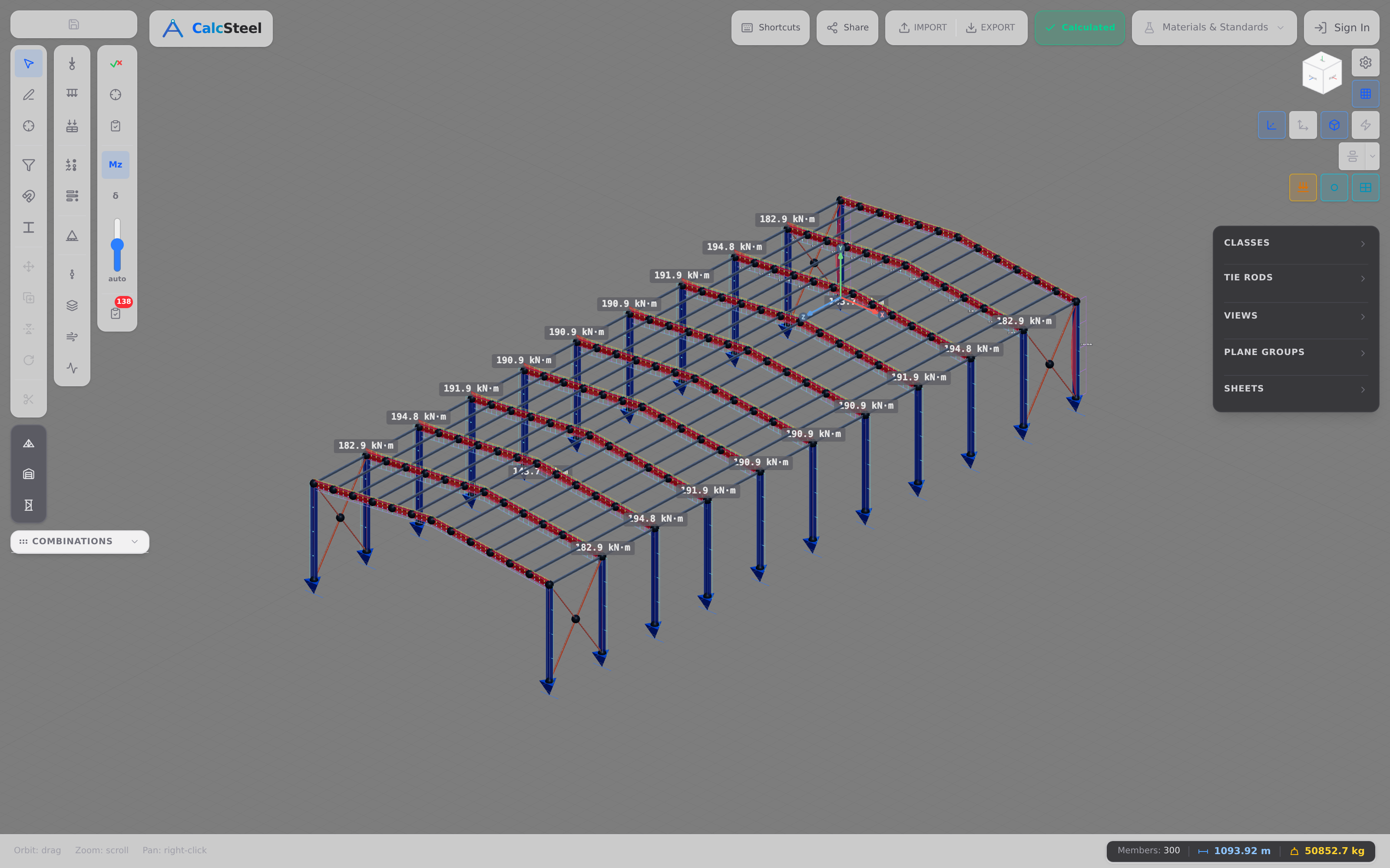
That frame isn't a textbook cartoon — it's a real steel model you can build in the CalcSteel editor, and the same FEM engine that split the bases also draws its whole-structure free body diagram, painting the support-reaction arrows straight onto the model. Every calculation in this guide, from a single beam to this frame, is the identical act: isolate a body, show every force, and demand that it balance.
From free body diagram to a full analysis
Here is the quiet secret of every structural analysis program, including the CalcSteel FEM engine: the finite element method is a free body diagram written at every single node. When you draw an FBD by hand, you isolate one body, replace its supports with reaction forces, and write ΣFx = 0, ΣFy = 0, ΣM = 0. The solver does exactly that — for every joint in the model at once.
Instead of choosing one body to isolate, the engine isolates all of them. It writes the equilibrium of each node (every force pulling on that node from every connected member, plus applied loads and reactions) and assembles those thousands of little free body diagrams into one large system of equations, then solves it in a single step. So the beam you balanced by hand in the reactions example and a 400-member steel building are the same physics at two scales — one body cut free and balanced, versus every body cut free and balanced simultaneously.
This is why the whole-frame result from earlier holds up. Isolate the entire fixed-base portal as one free body and equilibrium pins the totals exactly — ΣFy = 120 kN of vertical reaction balancing the gravity load, ΣFx = −20 kN balancing the wind. The engine reported precisely those totals. The split between the two bases (roughly 55.2 kN and 64.8 kN vertical, with nearly all the horizontal reaction gathering at the leeward base) is statically indeterminate — there is no hand formula for it — yet it is still just node-by-node equilibrium, which is why the FEM engine finds it while the whole-body FBD still guarantees the totals it must sum to.
And the free body diagram is only the first move. Once CalcSteel has the internal forces at every section, it classifies each member and runs the code check — NBR 8800, AISC 360, or Eurocode 3 — comparing demand against capacity and colouring every member by its utilization ratio. You get from “forces balanced” to “section verified” without leaving the browser. Draw the picture by hand to understand it; let the engine draw ten thousand of them to build with it. Try it in the CalcSteel editor.
Common mistakes & FAQ
Almost every wrong answer in statics traces back to a wrong free body diagram, not wrong arithmetic. Here are the six errors that show up again and again — check your sketch against them before you write a single equation.
- Forgetting a reaction — especially a moment. A roller gives one force, a pin gives two, and a fixed support gives three: horizontal, vertical, and a moment reaction. Leaving out that moment at a built-in end is the most common way to turn a solvable problem into nonsense.
- Drawing internal forces on a whole-body FBD. Internal axial, shear and moment only exist once you cut. On the free body of the intact structure they are invisible — they live inside it. Draw them only on the FBD of a cut piece.
- Getting Newton's third law backwards at a cut. When you section a member, the internal force appears equal and opposite on the two pieces. If a cut face shows shear pointing up on the left piece, it must point down on the right piece. Flip one and your two half-checks will never agree.
- Omitting self-weight when it matters. For a quick beam demo the point load dominates, but for a long-span girder or a heavy column the member's own weight is a real external load — put it on the diagram.
- Mixing two bodies' forces on one diagram. One free body diagram = one isolated body. The moment you let forces from the neighbouring member creep in, equilibrium stops meaning anything. If you need both, draw two diagrams.
- Assuming a reaction direction and then not trusting the sign. Guessing a direction is completely legitimate — that is the whole point of the sign convention. If the algebra returns a negative value, the force simply points the other way. Do not “fix” it by hand; the minus sign already fixed it.
Frequently asked questions
Do you include internal forces in a free body diagram? Not on a whole-body FBD — internal forces are self-cancelling pairs inside the body, so they never appear there. They become external, and therefore drawn, only on the free body diagram of a piece you have cut free with the method of sections. That cut is exactly what exposes the axial N, shear V and moment M.
How many equilibrium equations does a free body diagram give? In a plane, three per body: ΣFx = 0, ΣFy = 0, ΣM = 0. That means one FBD can solve up to three unknowns. More unknown reactions than equations and the structure is statically indeterminate — you need compatibility and stiffness, i.e. an FEM solver like the CalcSteel engine.
What is the difference between a free body diagram and a force diagram? A free body diagram is the sketch of the isolated body with every force shown at its point and direction of action. A force diagram (as in graphic statics) is the separate polygon you build by laying those force vectors tip-to-tail to find an unknown — it closes only if the body is in equilibrium. The FBD tells you which forces exist; the force diagram is one graphical way to solve for them.
Why does a truss joint FBD have no moment equation? Because at an idealised pin joint every member force passes through the same point — the forces are concurrent. Concurrent forces produce no moment about that point, so ΣM = 0 is automatically satisfied and carries no information. Only ΣFx = 0 and ΣFy = 0 remain, which is exactly why the method of joints uses two equations per joint.
Can I always replace a distributed load with its resultant? Only for the external equilibrium of the free body you drew: reactions come out exactly right with W = wL at the centroid. Anything internal — shear and moment diagrams, deflections, the load path inside the body — depends on where the load really sits. The 6 m beam above proves it: the resultant gives the correct 45 kN reactions, but using it after cutting the beam at 2 m would inflate the bending moment from 60 kN·m to 90 kN·m.
Key takeaways
One drawing underpins the entire discipline. Master the free body diagram and the rest of structural analysis becomes a matter of choosing what to isolate.
- A free body diagram is one body cut free from the world, with every external force and moment — applied loads, self-weight, and the reactions from supports and neighbours — drawn on it, and nothing internal.
- Isolate a whole beam → you get the reactions. The simply-supported span (L = 8 m, P = 40 kN at 3 m) gives RA = 25 kN and RB = 15 kN, and the CalcSteel engine returned exactly that.
- A distributed load enters as its resultant — but only for reactions. 15 kN/m over 6 m acts like 90 kN at the centroid (R = 45 kN each side); the moment you cut for internal forces, use only the load on the kept piece — 60 kN·m at x = 2 m, not 90.
- Cut it and isolate a piece → you get the internal forces. At x = 2 m the cut FBD carries V = 25 kN and M = 50 kN·m; at x = 5 m, V = −15 kN and M = 45 kN·m. A shear-force / bending-moment diagram is just this cut evaluated at every section.
- Isolate a single truss joint → you get the member forces. Concurrent forces, so only ΣFx and ΣFy apply: the diagonals run at 18.0 kN compression and the bottom chord at 10.0 kN tension — pure two-force members, exactly as the engine confirmed.
- Isolate a whole frame → its reactions balance everything. Even for the indeterminate fixed-base portal, the whole-body FBD pins ΣFy = 120 kN and ΣFx = −20 kN exactly, while only FEM resolves how they split between the bases.
Ready to draw your own? Balance any beam for free — no login for the math — in the CalcSteel beam calculator, or build a full model with reactions, internal forces and code checks in the editor. Students: CalcSteel is free through /education, so the same real FEM engine that automates the free body diagram is yours to learn on from day one.
Sources
Try CalcSteel for free
Model, analyze and design steel structures in your browser. No install, no signup.
Open the 3D editor