1.5mm to Gauge: 16 Gauge, and a 1.5 mm Wall Stud Sized End to End with the Governing Load Case
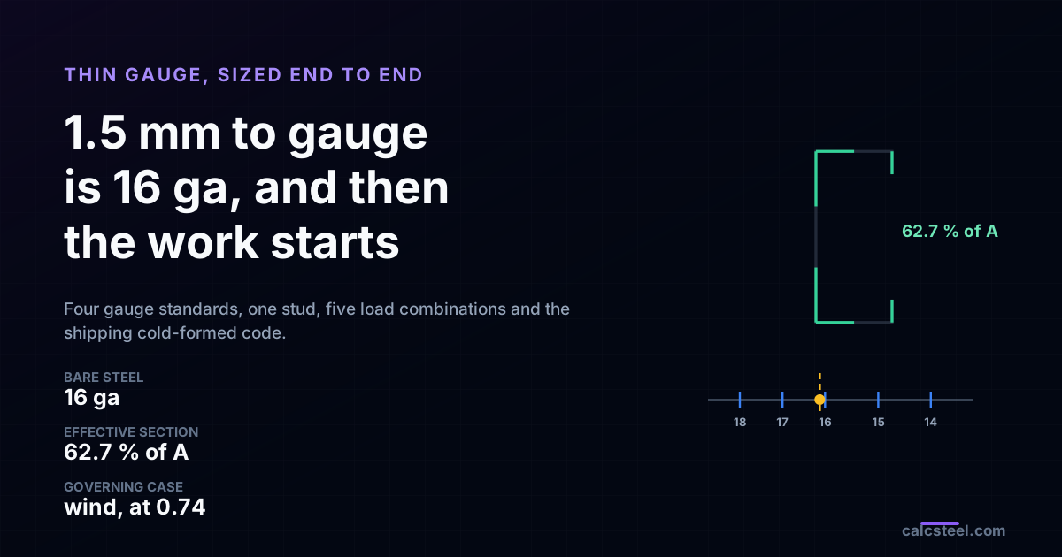
1.5 mm is 16 gauge in bare steel, and only in bare steel: on the galvanized and stainless scales the nearest row is 17, and in aluminium it is 15. That is the whole conversion, and it is the easy half. The hard half is what a 1.5 mm section actually carries, because at that thickness the gross properties are not the properties. This guide answers the conversion in one table, then sizes a real 1.5 mm wall stud end to end on the CalcSteel engine, finds the load combination that governs it, and shows why the check that finally decides the section is not a strength check at all.
Key takeaways
- 1.5 mm has four different gauge answers. Bare steel 16 (1.5189 mm, 1.26 % over), galvanized 17 (1.4605 mm), stainless 17 (1.4300 mm), aluminium 15 (1.4503 mm). Only the bare-steel scale says 16
- The thickness you design with is the base steel, coating excluded. A Z275 galvanized coat is 0.0386 mm, so a nominal 1.5 mm sheet is designed as 1.4614 mm, and the worked stud goes from 0.743 to 0.768 on that alone
- At 1.5 mm the section is not the section. At full yield the effective area is 62.7 % of the gross area and the effective section modulus is 74.2 % of the gross Sx, both computed by the shipping effective-width module
- The gravity combination is not the one that sizes the wall. The engine returns 0.276 for 1.4G + 1.4Q and 0.743 for 1.4G + 0.7Q + 1.4W, a factor of 2.7 on the same stud
- Strength was never the problem. The 1.5 mm stud passes every strength check and then deflects 8.60 mm under characteristic wind, which is H/349: it clears H/240 and H/300 and misses H/360
The conversion is the easy half
Somebody hands you a drawing that says 1.5 mm and a supplier who talks in gauge. The conversion takes one line: 1.5 mm is 16 gauge, on the Manufacturers' Standard Gauge for uncoated sheet steel, where 16 ga is 0.0598 in, which is 1.5189 mm. Your 1.5 mm is 1.26 % under that nominal row, closer to 16 than to anything else on the scale.
Then the trouble starts, in two places. The first is that the sentence above is only true for bare steel. Galvanized sheet, stainless and aluminium each kept a different gauge standard, and on those scales the row nearest 1.5 mm is 17, 17 and 15. A galvanized stud sold as 16 gauge is not 1.5 mm, it is 1.6129 mm, and the difference is not rounding.
The second is that none of this tells you whether 1.5 mm is enough. Thickness is a purchasing number. What decides a member is the force it carries, the way it buckles and the load combination that turns out to govern, and at 1.5 mm all three behave in ways that a thicker section does not prepare you for. So this article does both halves: the conversion table, and then one real 1.5 mm stud taken from tributary area to final verdict.
1.5 mm to gauge, on all four standards
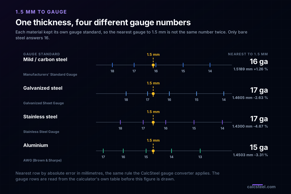
Gauge is not one scale. It is four legacy scales that never merged, so converting a thickness to a gauge number requires you to say which material you are holding. Here is 1.5 mm against each, with the nearest row picked by absolute error in millimetres, which is the rule the CalcSteel converter applies.
| Material | Gauge standard | Nearest gauge | That row, in mm | Error vs 1.5 mm |
|---|---|---|---|---|
| Mild / carbon steel | Manufacturers' Standard Gauge | 16 ga | 1.5189 mm | +1.26 % |
| Galvanized steel | Galvanized Sheet Gauge | 17 ga | 1.4605 mm | -2.63 % |
| Stainless steel | Stainless Steel Gauge | 17 ga | 1.4300 mm | -4.67 % |
| Aluminium | AWG (Brown & Sharpe) | 15 ga | 1.4503 mm | -3.31 % |
Read the third column again. The answer to "what gauge is 1.5 mm" changes by two whole gauge numbers depending on what the sheet is made of, and the spread between the four candidate thicknesses is 0.0889 mm, which is 5.9 % of the thickness you started with.
The reverse direction is worse, because it is the one people quote from memory. Sixteen gauge is 1.5189 mm in bare steel, 1.6129 mm galvanized, 1.5875 mm in stainless and 1.2903 mm in aluminium. Order 16 ga galvanized expecting 1.5 mm and you get 7.5 % more steel than you planned, which is good for capacity and bad for the fabrication drawing that assumed a thickness.
Why one thickness has four gauge numbers
Gauge numbers were never thicknesses. They started as counts, of how many times a sheet had been drawn through a set of rolls, and the count ran up as the sheet got thinner. That is why the scale is inverse: 10 gauge is thick, 26 gauge is a shim.
Each trade then fixed the count against a different physical reference. The Manufacturers' Standard Gauge for sheet steel is anchored on weight, 41.82 lb per square foot per inch of thickness, which is why its rows land on numbers like 0.0598 in. The Galvanized Sheet Gauge is the same idea with the zinc counted in, so every row is thicker than its bare-steel twin. The Stainless Steel Gauge is built on simple fractions of an inch, so 16 ga is exactly 1/16 in. Aluminium borrowed the American Wire Gauge, a geometric series defined by a formula rather than a table.
Four references, four ladders, no conversion between them. Which leads to the only rule worth keeping: specify millimetres or inches on the drawing and treat the gauge number as shop vocabulary. "1.5 mm CRS" means one thing everywhere. "16 gauge" means four things and gets one of them delivered.
Convert any thickness yourself
The converter below runs the same four tables this article does, in both directions, and adds the weight per square metre. Type 1.5 mm, or any thickness, and read the nearest gauge on each standard; or type a gauge number and see the four thicknesses it means. No sign-up, and the numbers come from the tables, not from a generative guess.
Uncoated cold- or hot-rolled sheet steel. Nominal weight basis 41.82 lb/ft²·in.
Thickness
1.519 mm
0.0598 in
Weight / area
11.92 kg/m²
2.442 lb/ft²
Reverse — thickness → nearest gauge
Δ% is how far the standard gauge sits from your measured thickness — useful when a mic reads between two gauges. Click the gauge to load it above.
Weight per area — w = ρ · t
t = 0.0598 in × 25.4 = 1.519 mm
w = ρ · t = 7,850 kg/m³ × 1.519 mm ÷ 1000 = 11.92 kg/m²
= 11.92 × 0.204816 = 2.442 lb/ft²
16 gauge across all four materials
same number → different thicknessA 16 ga part is 1.519 mm in steel but 1.613 mm galvanized and only 1.290 mm in aluminum — never mix gauge numbers across materials on a drawing. Specify the thickness in mm/in when it matters.
Export — free, no login
Take the numbers with you: a copy-ready spec for 16 ga Steel, or the whole gauge table as CSV (both unit systems in the file).
Send this gauge into an engine
The thickness you picked feeds a real weight/BOM engine — not just a related link.
Open in Steel Weight Calculator1 m² coupon · Steel · 1.519 mm pre-loadedCold-formed sections built from ≈ this gauge (matched against 418 cold-formed catalog sections)
Cold-formed local buckling — effective width
NBR 14762 · AISI S100A capability a plain converter can’t have: how wide can a flat element of this 1.519 mm sheet be before it buckles locally? Winter’s effective-width method, λ = (1.052/√k)·(b/t)·√(fy/E).
Slenderness λ
0.979
Factor ρ
0.792
Effective width bₑ
63.3 mm
Full-effective ≤
55 mm
A 80 mm flat at this gauge is slender (b/t = 52.7, λ = 0.98 > 0.673): only 63 mm is structurally effective. Keep flats below 55 mm for full effectiveness, or add a stiffening lip.
Mild / carbon steel — full gauge table (Manufacturers' Standard Gauge)
| Gauge | in | mm | kg/m² | lb/ft² |
|---|---|---|---|---|
| 3 ga | 0.2391 | 6.073 | 47.67 | 9.764 |
| 4 ga | 0.2242 | 5.695 | 44.7 | 9.156 |
| 5 ga | 0.2092 | 5.314 | 41.71 | 8.543 |
| 6 ga | 0.1943 | 4.935 | 38.74 | 7.935 |
| 7 ga | 0.1793 | 4.554 | 35.75 | 7.322 |
| 8 ga | 0.1644 | 4.176 | 32.78 | 6.714 |
| 9 ga | 0.1495 | 3.797 | 29.81 | 6.105 |
| 10 ga | 0.1345 | 3.416 | 26.82 | 5.493 |
| 11 ga | 0.1196 | 3.038 | 23.85 | 4.884 |
| 12 ga | 0.1046 | 2.657 | 20.86 | 4.272 |
| 13 ga | 0.0897 | 2.278 | 17.89 | 3.663 |
| 14 ga | 0.0747 | 1.897 | 14.89 | 3.051 |
| 15 ga | 0.0673 | 1.709 | 13.42 | 2.748 |
| 16 ga | 0.0598 | 1.519 | 11.92 | 2.442 |
| 17 ga | 0.0538 | 1.367 | 10.73 | 2.197 |
| 18 ga | 0.0478 | 1.214 | 9.53 | 1.952 |
| 19 ga | 0.0418 | 1.062 | 8.33 | 1.707 |
| 20 ga | 0.0359 | 0.912 | 7.16 | 1.466 |
| 21 ga | 0.0329 | 0.836 | 6.56 | 1.344 |
| 22 ga | 0.0299 | 0.759 | 5.96 | 1.221 |
| 23 ga | 0.0269 | 0.683 | 5.36 | 1.099 |
| 24 ga | 0.0239 | 0.607 | 4.77 | 0.976 |
| 25 ga | 0.0209 | 0.531 | 4.17 | 0.854 |
| 26 ga | 0.0179 | 0.455 | 3.57 | 0.731 |
| 27 ga | 0.0164 | 0.417 | 3.27 | 0.67 |
| 28 ga | 0.0149 | 0.378 | 2.97 | 0.608 |
| 29 ga | 0.0135 | 0.343 | 2.69 | 0.551 |
| 30 ga | 0.012 | 0.305 | 2.39 | 0.49 |
| 31 ga | 0.0105 | 0.267 | 2.09 | 0.429 |
| 32 ga | 0.0097 | 0.246 | 1.93 | 0.396 |
| 33 ga | 0.009 | 0.229 | 1.79 | 0.368 |
| 34 ga | 0.0082 | 0.208 | 1.63 | 0.335 |
| 35 ga | 0.0075 | 0.19 | 1.5 | 0.306 |
| 36 ga | 0.0067 | 0.17 | 1.34 | 0.274 |
Click any row to select it. Weights use ρ = 7,850 kg/m³. Toggle SI/Imperial above.
The thickness you design with is not the one on the chart
This one costs money and almost nobody applies it on the first project. Cold-formed design codes want the base steel thickness, with the metallic coating excluded. AISI S100 puts it in A2.4, NBR 14762 in its definitions, EN 1993-1-3 in 3.2.4. The zinc is corrosion protection; it carries nothing.
A Z275 coating is 275 g of zinc per square metre counting both faces. At a density of 7130 kg/m3 that is 0.0386 mm of zinc. So a sheet sold as nominal 1.5 mm galvanized is designed as 1.4614 mm, a 2.57 % haircut before a single load is applied.
Small number, real effect, because thin sections are penalised twice for thinness: the area drops with t, and the local buckling reduction gets worse as well. Re-running the worked stud further down at 1.4614 mm instead of 1.5000 mm moves the governing utilisation from 0.743 to 0.768 and the wind deflection from 8.60 mm to 8.81 mm. That is 3.4 % of utilisation bought by a coating you were going to specify anyway.
The rule of thumb that follows: if the quotation says nominal thickness and the sheet is galvanized, take the coating off before you design. If it says base metal thickness, it has already been taken off. If it says 16 gauge, ask which of the four standards, and then ask again whether that is before or after the zinc.
From a thickness to a member
A gauge chart stops at the sheet. Every structural question starts one step later, when that sheet has been roll-formed into a shape and asked to carry something. At 1.5 mm the shape is doing almost all of the work, because the material is far too thin to resist anything on its own: a flat 1.5 mm strip 90 mm wide buckles under a load you could apply by hand, and the same strip bent into a lipped channel carries tens of kilonewtons.
That is also the source of the trap. Once the sheet is a section, it has an area, a moment of inertia and a section modulus, and a catalogue will print all three. Those are gross properties, computed from the outline. A thin section does not get to use all of them, and how much it loses is a function of thickness. The rest of this article is one member, sized end to end, with that loss measured rather than assumed.
If you want the same treatment for a flat plate rather than a formed section, the sibling article on plate weight takes an 8 mm plate through the same end-to-end route with its own governing combination.
The worked member: a 1.5 mm load-bearing wall stud
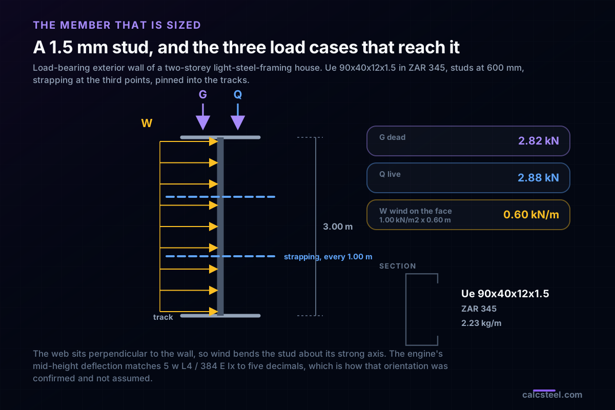
The most common place a structural 1.5 mm section shows up is a light-steel-framing wall, so that is what gets sized here. Ground floor exterior wall of a two-storey house, carrying the floor above and the roof, and taking wind on its face.
- Section: Ue 90x40x12x1.5, a lipped channel, 2.23 kg/m. Gross A = 2.8425 cm2, Ix = 36.794 cm4, Sx = 8.1763 cm3.
- Steel: ZAR 345, fy = 345 MPa, E = 200 GPa.
- Geometry: storey 3.00 m, studs at 600 mm centres, horizontal strapping and blocking at the third points, so 1.00 m between restraints about the minor axis and against twist. Pinned into the top and bottom tracks.
- Tributary: the floor above spans 4.80 m and halves onto this wall, giving 1.44 m2 of floor per stud.
The web sits perpendicular to the wall plane, which is how studs are built, so wind bends the stud about its strong axis. That is worth confirming rather than assuming, and the engine confirms it: under a transverse UDL of 0.600 kN/m the mid-height deflection comes back as 8.5995 mm, against a closed-form 5 w L4 / 384 E Ix of 8.5995 mm, an error of 0.000045 %. The same load about the weak axis would have given 47.94 mm. The moment lands at 67.5 kN.cm against w L2 / 8 = 67.5 kN.cm, exact.
At 1.5 mm, a third of the section does not count
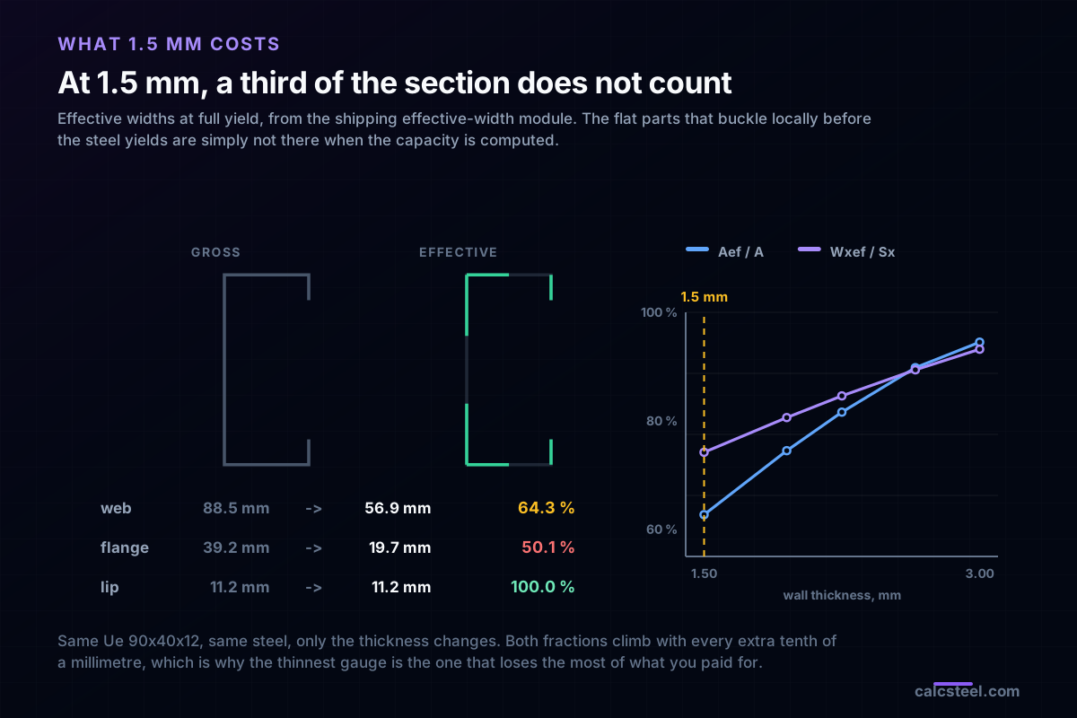
Here is the part a gauge chart cannot tell you. The flat elements of a thin section buckle locally, in a ripple across the plate, well before the steel reaches its yield stress. The design codes do not forbid that; they account for it by deleting the part of each flat that has stopped carrying and keeping the rest. That is the effective width method, and Winter's formula is its engine.
Run the shipping effective-width module on this section, at full yield stress, and here is what survives:
| Element | Flat width | b / t | Effective | Kept |
|---|---|---|---|---|
| Web | 88.5 mm | 59.0 | 56.9 mm | 64.3 % |
| Flange | 39.2 mm | 26.2 | 19.7 mm | 50.1 % |
| Lip | 11.2 mm | 7.5 | 11.2 mm | 100.0 % |
Add it up and the effective area is 62.7 % of the gross area, 1.7811 cm2 out of 2.8425 cm2, and the effective section modulus in bending is 74.2 % of the gross Sx, 6.063 cm3 out of 8.1763 cm3. The lip survives intact, which is the whole reason it is there; the flange loses half of itself.
One qualification that matters and gets skipped: those fractions are computed at the stress the element actually sees, not at yield by decree. A short, stocky member is stressed to yield and pays the full penalty. A long slender member buckles globally at a much lower stress, its plates never reach the local-buckling threshold, and its effective area comes back at or near 100 % of gross. In the worked stud below, global buckling caps the stress at 149.6 MPa, and the compression check comes back with 81.8 % of the gross area instead of the 62.7 % that full yield would cost, while the bending check still runs on 6.063 cm3. Thin-gauge penalties are real, and they are stress-dependent.
Now sweep the thickness and hold everything else. The same Ue 90x40x12, same steel, same geometry:
| Thickness | Nearest gauge | Aef / A | Wxef / Sx | Mass |
|---|---|---|---|---|
| 1.50 mm | 16 ga | 62.7 % | 74.2 % | 2.231 kg/m |
| 1.95 mm | 14 ga | 74.5 % | 80.6 % | 2.880 kg/m |
| 2.25 mm | 13 ga | 81.6 % | 84.6 % | 3.307 kg/m |
| 2.65 mm | 12 ga | 89.8 % | 89.4 % | 3.870 kg/m |
| 3.00 mm | 11 ga | 94.5 % | 93.2 % | 4.357 kg/m |
The penalty falls monotonically with thickness, and 1.5 mm sits at the bottom of it. That is the honest structural meaning of "16 gauge": the thinnest common structural sheet, and the one that throws away the largest share of the section you paid to form.
Three load cases reach the stud
Nothing has been combined yet. These are the three separate actions, at characteristic values, per stud.
G, permanent. Floor above at 1.20 kN/m2 and roof at 0.35 kN/m2 over the 1.44 m2 tributary, plus 0.588 kN for the upper-storey wall strip standing on this one. Total 2.82 kN of axial compression.
Q, variable. Residential live load 1.50 kN/m2 on the floor and 0.50 kN/m2 on the roof, over the same tributary. Total 2.88 kN, also axial.
W, wind. A net 1.00 kN/m2 on the wall face, which over the 0.60 m spacing is a line load of 0.600 kN/m along the stud. Pinned top and bottom, so the moment at mid-height is w L2 / 8 = 0.675 kN.m.
Notice what is already unusual. The two gravity cases are pure axial and between them total 5.70 kN, which is 5.8 % of the squash load A fy = 98.07 kN. The wind case carries no axial at all and produces the only bending in the problem. They are not comparable until they are combined, and that is exactly where the answer stops being obvious.
The combination that governs, and it is not gravity
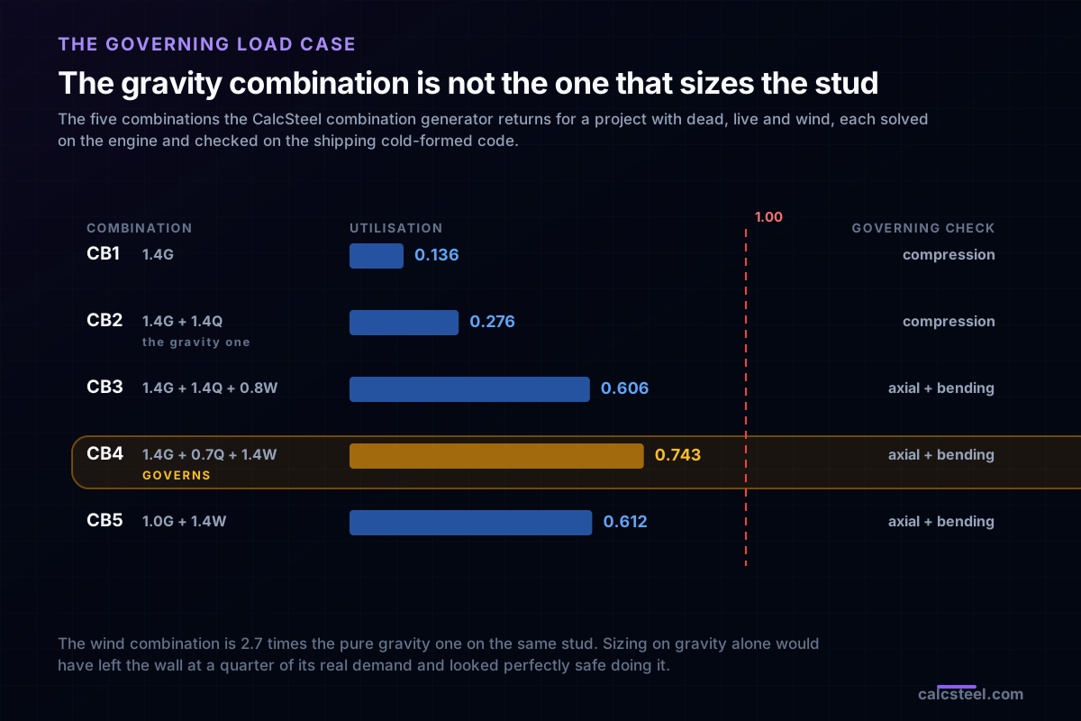
Ask the CalcSteel combination generator for a project that declares one permanent, one variable and one wind case, and it returns five combinations. Each was then built as its own factored analysis, solved on the engine, and checked on the shipping cold-formed code.
| Combination | Factors | N | M | Utilisation | Governing check |
|---|---|---|---|---|---|
| CB1 | 1.4G | 3.948 kN | 0 | 0.136 | compression |
| CB2 | 1.4G + 1.4Q | 7.980 kN | 0 | 0.276 | compression |
| CB3 | 1.4G + 1.4Q + 0.84W | 7.980 kN | 0.567 kN.m | 0.606 | axial + bending |
| CB4 | 1.4G + 0.7Q + 1.4W | 5.964 kN | 0.945 kN.m | 0.743 | axial + bending |
| CB5 | 1.0G + 1.4W | 2.820 kN | 0.945 kN.m | 0.612 | axial + bending |
CB4 governs, at 0.743. The pure gravity combination that most people reach for, CB2, comes in at 0.276. The governing case is 2.7 times the one that looks like the big one, on the same stud, with the same steel.
The mechanism is visible in the table. CB2 has the largest axial force in the set and no moment at all, and axial force is the thing this member is good at: 7.980 kN against a design compression capacity of 28.97 kN. CB4 gives up a third of that axial, in exchange for the full 1.4 on wind, and the moment term it buys is worth far more than the axial it gave back. CB5 drops the axial further still and lands below CB4, which is the other half of the same lesson: the worst case is neither the most axial nor the least, it is the mix that maximises the interaction sum.
And the interaction sum is the check. NBR 14762 art. 9.9, the same form AISI S100 uses, asks for N/Nc plus an amplified Mx/Mcx. On CB4 the axial term is 0.206, the bending term before amplification is 0.497, and the second-order amplifier 1/(1 - N/Nex) pushes the bending part up to the 0.743 total.
Does the 1.5 mm stud pass? The full check
On the governing combination CB4, member by member of the check list the shipping code runs:
- Slenderness: KL/r = 83.4 about the strong axis over the full storey and 65.6 about the minor axis between restraints, against the limit of 200. Ratio 0.417, and it is a geometry check, not a demand.
- Compression: 5.964 kN against Nc,Rd = 28.97 kN. Ratio 0.206.
- Bending about the strong axis: 0.945 kN.m against Mcx,Rd = 1.9016 kN.m. Ratio 0.497.
- Axial plus bending, with amplification: 0.743. This governs.
- Cross-section yielding, the linear form the norm asks for alongside the stability equation: 0.703.
- Shear: negligible, as it always is on a stud.
So the answer to "is 1.5 mm strong enough here" is yes, with 26 % of margin. Take the zinc off and design at the base metal thickness of 1.4614 mm and it becomes 0.768, still a pass with 23 % of margin.
Worth pausing on the compression capacity, because it is where a lipped channel surprises people. Nc,Rd = 28.97 kN is 29.5 % of the squash load. The reason is not local buckling; it is flexural-torsional buckling. A lipped channel is mono-symmetric, its shear centre sits outside the section, and the member wants to twist as it buckles. With restraints every 1.00 m the engine reports the elastic torsional load at a level that drags the whole capacity down. Move the restraints and watch what happens:
| Restraint spacing | Nc,Rd |
|---|---|
| 3.00 m, no intermediate restraint | 7.97 kN |
| 1.50 m, mid-height | 17.80 kN |
| 1.00 m, third points | 28.97 kN |
| 0.75 m, quarter points | 34.42 kN |
| 0.60 m | 36.79 kN |
An unrestrained 3.00 m stud has 7.97 kN of compression capacity, which is less than the 7.980 kN that CB2 already applies. The same stud with strapping at the third points has 3.6 times that. On thin-gauge work the strapping is not a detail, it is a structural member, and leaving it out of the model is the fastest way to a wall that calculates fine and does not behave.
Strength was never the problem
The stud passes every strength check with margin to spare, and then it fails on the one line nobody puts on the cover sheet.
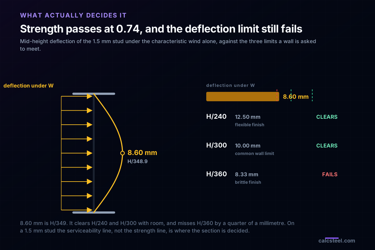
Under the characteristic wind alone, 0.600 kN/m, the engine returns a mid-height deflection of 8.60 mm. The storey is 3000 mm, so that is H/349.
| Limit | Value | Typical use | Verdict |
|---|---|---|---|
| H/240 | 12.50 mm | flexible finish, metal cladding | clears |
| H/300 | 10.00 mm | common wall limit | clears |
| H/360 | 8.33 mm | brittle finish, plaster and board | fails |
It misses H/360 by a quarter of a millimetre. And H/360 is exactly the limit a light-steel-framing wall usually has to meet, because the thing screwed to the studs is gypsum board and gypsum board cracks.
There is a legitimate way out, and it is worth knowing rather than discovering by argument. IBC Table 1604.3 allows components and cladding with brittle finishes to be checked against 0.42 times the component wind load, which reflects the lower return period appropriate to serviceability. Apply it and the deflection becomes 3.61 mm, comfortably inside H/360. Which wind you check against is a decision, not a detail, and on a 1.5 mm stud it is the decision: the difference between 8.60 mm and 3.61 mm is the difference between changing the section and not.
The general point survives either way. On thin-gauge members the stiffness falls faster than the strength does, because capacity scales roughly with the effective section modulus while deflection scales with the full moment of inertia of a very thin shape. Serviceability is normally the binding constraint, and any thin-gauge design that only reports strength ratios has not finished.
Three levers, and only two of them work
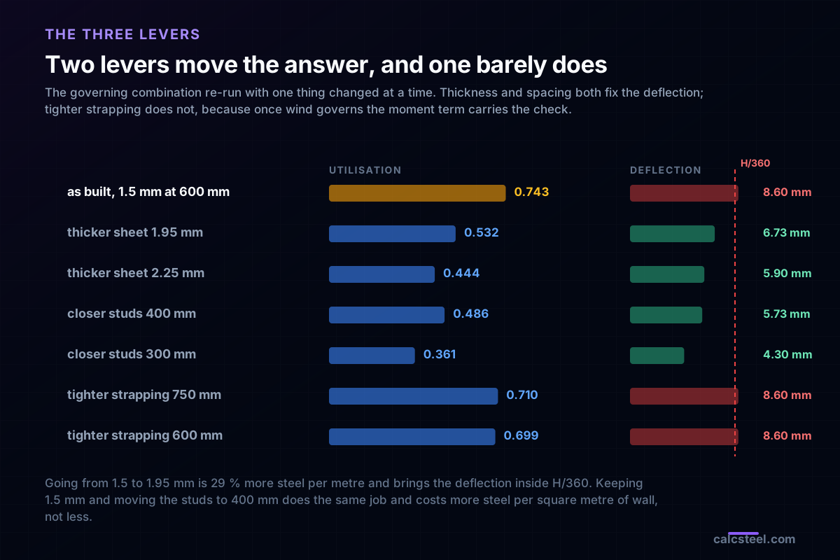
Suppose you take H/360 at full wind and have to fix it. The governing combination was re-run with one variable changed at a time, everything else held.
| Change | Utilisation | Deflection | H/360 |
|---|---|---|---|
| As built, 1.5 mm at 600 mm | 0.743 | 8.60 mm | fails |
| Thicker sheet, 1.95 mm | 0.532 | 6.73 mm | clears |
| Thicker sheet, 2.25 mm | 0.444 | 5.90 mm | clears |
| Closer studs, 400 mm | 0.486 | 5.73 mm | clears |
| Closer studs, 300 mm | 0.361 | 4.30 mm | clears |
| Tighter strapping, 750 mm | 0.710 | 8.60 mm | fails |
| Tighter strapping, 600 mm | 0.699 | 8.60 mm | fails |
Thickness works. Going from 1.5 mm to 1.95 mm is 29 % more steel per metre of stud, drops the utilisation to 0.532 and brings the deflection to 6.73 mm. It also improves the effective fractions, from 62.7 % to 74.5 % of area, so part of the extra metal buys back metal you already had.
Spacing works, and costs more than it looks. Keeping 1.5 mm and moving the studs to 400 mm gives 0.486 and 5.73 mm, a better result than the thicker sheet. But steel per square metre of wall goes from 3.72 to 5.58 kg/m2, where the 1.95 mm option at 600 mm sits at 4.80 kg/m2. Closer studs also means more track, more screws and more labour.
Strapping barely moves it, and that surprises people who just saw strapping triple the compression capacity two sections ago. Both things are true. Going from 1.00 m to 0.60 m does lift Nc,Rd from 28.97 kN to 36.79 kN, but on the governing combination the axial term is only 0.206 of the total, so improving it moves the answer from 0.743 to 0.699 and does nothing at all to the deflection. Once wind governs, the moment term carries the check, and only section stiffness or tributary width touches it.
What the codes ask, on three continents
Thin-gauge steel has its own specification everywhere, separate from the hot-rolled one, because none of the hot-rolled assumptions survive at 1.5 mm.
- AISI S100 (North America) is the reference the others are related to. Effective width in Appendix 1 and Chapter B, the direct strength method as an alternative, base metal thickness in A2.4, and a minimum delivered thickness of 95 % of the design value.
- NBR 14762 (Brazil) is the standard CalcSteel runs for every cold-formed bar. Effective width in Anexo D, compression in art. 9.7, flexure in art. 9.8.2, and art. 9.9 requiring both the amplified stability equation and the linear cross-section equation, with the worse one governing. Section geometry comes from NBR 6355, steel grades from NBR 7008.
- EN 1993-1-3 (Europe) does the same job with different vocabulary: effective cross-section in section 5, distortional buckling handled explicitly through the stiffener spring model, and a rounded-corner treatment that a square-corner idealisation slightly overstates.
- AS/NZS 4600 and IS 811 follow the AISI structure closely enough that a check written for one transfers with the safety factors changed.
One implementation note about the numbers above, stated because it changes them. The effective-width module used here takes the compression flange on the unstiffened plate coefficient, k = 0.43, rather than the stiffened k = 4.0 that a lipped flange with an adequate stiffener is entitled to under AISI B4. That is the conservative side of the code: the real flange, with its 12 mm lip checked as adequate, would keep more than the 50.1 % reported. Every utilisation in this article is therefore on the safe side of what a full hand check would return.
The load combinations are a separate axis. The five used here are the NBR set. Under ASCE 7 the equivalent pair is 1.2D + 1.6L and 1.2D + 1.0W + 1.0L, with 0.9D + 1.0W for the uplift-led case, and the pattern of the result does not change: the combination that pairs a reduced live load with full wind is the one that sizes a wall stud.
Common mistakes, and the FAQ
"16 gauge is 1.5 mm." In bare steel, near enough. In galvanized it is 1.6129 mm and in stainless 1.5875 mm. Three answers, one sentence, and the sentence does not say which.
Designing at the nominal thickness of a coated sheet. The zinc does not carry load. Z275 is 0.0386 mm off the top, which took the worked stud from 0.743 to 0.768.
Using catalogue gross properties in a thin section. At 1.5 mm the effective section modulus is 74.2 % of the gross Sx. Using Sx directly overstates the bending capacity by a third.
Assuming the penalty is fixed. It is not: it is computed at the stress the plate sees. The same section keeps 81.8 % of its area in the compression check of this very article, against 62.7 % at yield, because global buckling capped the stress first.
Checking only the gravity combination. It was 0.276 here against 0.743 for the wind-led one. A stud wall is a beam-column, and its worst case has wind in it.
Leaving strapping out of the model. The same stud is worth 7.97 kN unrestrained and 28.97 kN with strapping at the third points.
Stopping at the strength ratio. Every strength check passed here, and the section still had to change for deflection at H/360.
Is 1.5 mm sheet structural? Yes, once it is formed. Flat it is nothing; as a lipped channel with restraints it carried a two-storey wall at 74 % utilisation in this example.
What is the metric equivalent people actually buy? Mills roll to mill thicknesses, not to gauge: 1.20, 1.50, 1.95, 2.25, 2.65 and 3.00 mm are the rows a cold-formed catalogue offers, which is why the sweep above uses them.
From a gauge number to a sized member
1.5 mm is 16 gauge, if the sheet is bare steel. It is 17 gauge galvanized, 17 stainless and 15 in aluminium, and the honest advice is to write the millimetres on the drawing and let the shop keep the gauge number as slang.
Then, if the sheet has a structural job, four things follow that the chart cannot tell you. Design at the base metal thickness, so 1.4614 mm for a nominal 1.5 mm with a Z275 coat. Expect to lose part of the section: 62.7 % of the area and 74.2 % of the section modulus survived at full yield here. Find the governing combination rather than assuming it, because the wind-led one came in at 2.7 times the gravity-led one. And finish on serviceability, because that is where the thin section was decided: every strength check passed, and 8.60 mm against an 8.33 mm limit is what would send this wall to 1.95 mm or to 400 mm spacing.
None of it is exotic. It is one member, five combinations and two limit states, and it is exactly the sequence the CalcSteel engine runs when you model a cold-formed wall and press calculate.
Sources
- 1.AISI S100, North American Specification for the Design of Cold-Formed Steel Structural Members (effective width, base metal thickness A2.4)
- 2.ABNT NBR 14762, Dimensionamento de estruturas de aco constituidas por perfis formados a frio (art. 9.7, 9.8.2, 9.9 and Anexo D)
- 3.ABNT NBR 6355, Perfis estruturais de aco formados a frio, and NBR 7008, Chapa de aco revestida com zinco
- 4.EN 1993-1-3, Eurocode 3: Design of steel structures, supplementary rules for cold-formed members and sheeting
- 5.ASCE/SEI 7, Minimum Design Loads and Associated Criteria for Buildings and Other Structures
- 6.International Building Code, Table 1604.3, deflection limits and the 0.42W component and cladding provision
- 7.CalcSteel sheet metal gauge chart and converter, the four gauge standards used here
Try CalcSteel for free
Model, analyze and design steel structures in your browser. No install, no signup.
Open the 3D editor