What Column for a 6 m Storey Height? Axial Plus Moment, Checked End to End
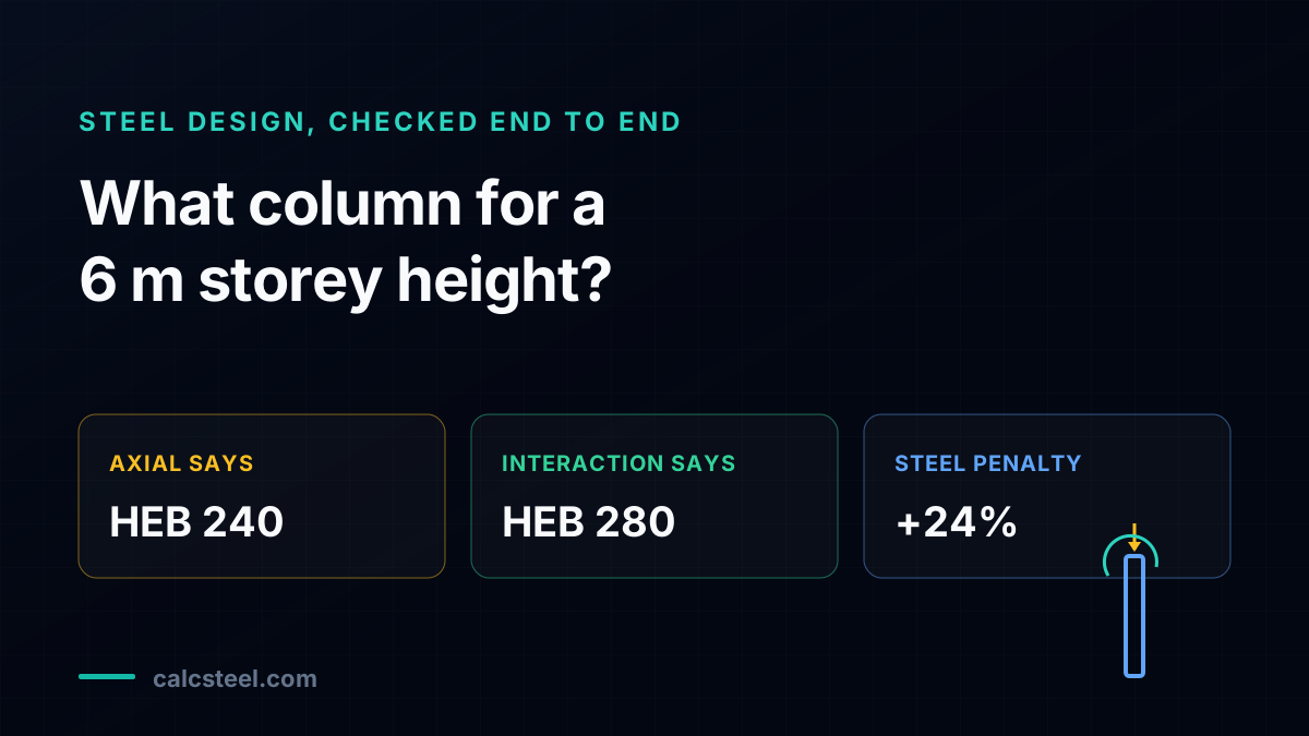
"What column for a 6 m storey height?" reads like a table lookup, and if the column only carried axial load it almost would be. This deep-dive puts one real storey column through the CalcSteel FEM engine, carrying 1400 kN of gravity axial and a 150 kN.m strong-axis moment, and races seven HEB sections through AISC 360 buckling, lateral-torsional buckling and the H1.1 interaction. The twist: the lightest section that passes on axial alone, HEB 240, fails the interaction at 1.49, because a 6 m unbraced length knocks down both capacities and the moment finishes the job. The column you build is HEB 280, 24 percent heavier, and a stronger steel cannot save the lighter one.
Key takeaways
- A column for a 6 m storey height is not sized by its axial load alone once a moment is present. On this worked column the demand is 1400 kN of axial plus a 150 kN.m strong-axis moment, and the section that carries the axial with room to spare, HEB 240 at a utilisation of 0.86, fails the combined check at an interaction ratio of 1.49.
- The 6 m unbraced length is the whole story. With K = 1 the buckling length is the full 6.0 m, so the minor-axis slenderness of the HEB 240 is 98.7, its buckling stress Fcr is only 170.6 MPa against a 355 MPa yield, and its design compression is phiPn = 1627 kN. The same 6 m also triggers lateral-torsional buckling in bending, dropping its flexural capacity from 324.6 to 275.9 kN.m.
- The AISC H1.1 interaction is what actually sizes the column. HEB 240 fails at 1.49 and HEB 260 still fails at 1.17. Only HEB 280, with phiPn = 2445 kN and phiMn = 413.3 kN.m, passes at 0.946. Sizing on axial stops at 83.2 kg/m; the interaction forces 103.1 kg/m, a 24 percent increase in steel bought entirely by the moment.
- Second-order effects make it worse before they make it right. The B1 amplifier lifts the 150 kN.m first-order moment to 195.3 kN.m on the HEB 240 and 173.6 kN.m on the HEB 280, because the axial load riding on the sideways deflection adds moment the first-order diagram never shows.
- A stronger steel cannot rescue the lighter section. Upgrading the HEB 240 from S355 to S460 raises its design compression only 4 percent, from 1627 to 1696 kN, because at this slenderness buckling, not yield, caps the stress. Its interaction ratio drops only to 1.35, still a failure. The levers are the section, the storey height and the moment, not the grade of steel.
The question that looks like a lookup, and why it is not
Ask a structural engineer "what column for a 6 m storey height" and the fast answer is a section off a capacity table. Find the shape whose axial capacity beats the load, done. If the column carried nothing but axial force that answer would even be close to right, because a pure column is sized by one number. The trap is that almost no real storey column carries only axial force. It also carries a moment, from an unbalanced floor beam, from frame action, from wind, and the moment does not politely wait its turn. It runs through the same interaction check as the axial load, and on a tall storey it is usually the moment that decides.
This article works one concrete column all the way through and lets the numbers settle the question. A single storey, 6.0 m floor to floor, one column carrying 1400 kN of gravity axial from the floors above and a 150 kN.m moment about its strong axis. We solve it on the CalcSteel finite element engine, cross-check the axial and the moment against hand statics, then race seven HEB sections, from HEB 200 to HEB 320, through AISC 360 buckling, lateral-torsional buckling and the H1.1 interaction. Here is the whole point in advance: the lightest section that passes on axial alone is not the column you build, the 6 m unbraced length quietly knocks both capacities down, and the interaction, not the axial table, names the winner.
The worked column: 6 m storey, HEB, S355, braced frame
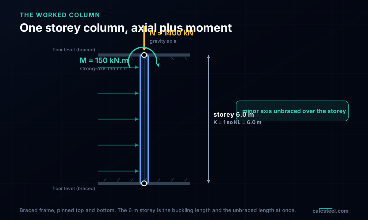
Here is the member we carry through the article. A single storey column, 6.0 m from the base connection to the floor above, an HEB hot-rolled wide-flange section in S355 steel (yield 355 MPa, modulus 200 GPa). It sits in a braced frame, so the storey does not sway and the effective-length factor is K = 1: the column is held in position at both floor levels but pinned for rotation, and its buckling length is the full 6.0 m. The floor beams frame into it at the top and bottom only, so between floors the minor axis is unbraced over the whole storey. Hold on to that last fact, because a 6 m unbraced length is what turns this from a lookup into a real check.
Two things load this column. The floors above stack gravity down it as axial compression, and a floor beam plus the lateral system deliver a strong-axis moment at the storey. A pure axial column would be sized by buckling alone. A column with a moment is a beam-column, and a beam-column is checked by an interaction equation that adds the two demands together. The question is not "which section carries 1400 kN", it is "which section carries 1400 kN and 150 kN.m at the same time, over 6 m".
Two demands, one column, and the length that governs both
The demand side is a pair of numbers, and neither depends on which section we pick.
- Axial compression, N = 1400 kN, the gravity load from the floors above resolved down this column line at the ultimate (LRFD) combination.
- Strong-axis moment, M = 150 kN.m, the first-order moment at the storey from the unbalanced beam and the lateral system.
Both are checked at the factored load, and both meet the same section at the same time. What the section changes is the capacity that answers them, and the 6 m storey height reaches into both capacities at once:
- In compression, the buckling length is K times the storey, 1.0 x 6.0 = 6.0 m. Divide by the minor-axis radius of gyration and you get the slenderness that sets the buckling stress. The taller the storey, the larger the slenderness, the smaller the capacity.
- In bending, the compression flange is braced only at the floors, so the unbraced length for lateral-torsional buckling is also 6.0 m. On a stocky HEB the plastic moment is reachable only up to a length of about 2.5 to 3.2 m; past that the flexural capacity falls. At 6 m we are well past it.
So the storey height is not a passive dimension in the background. It is the single variable that discounts the compression capacity and the bending capacity together, and it does so before the moment and the axial are even added up. Keep the number 6.0 m in mind: it is why the section that carries the axial cannot carry the pair.
The demand, and a hand check that matches to the digit
Drop the column into the CalcSteel engine, apply the 1400 kN axial and the transverse load that delivers the 150 kN.m, and read the results. The engine returns exactly what statics predicts, which is the point of running the control first:
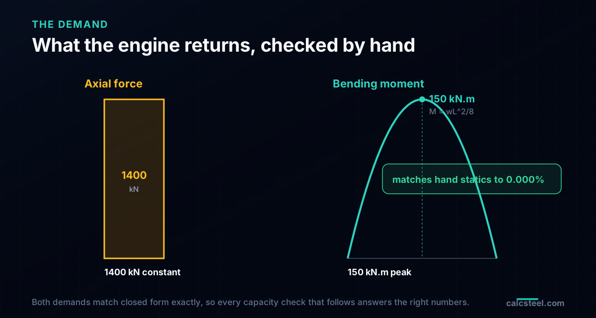
- Axial force in the column, N = 1400.0 kN, matching the applied gravity load to 0.000 percent.
- Peak strong-axis moment, M = 150.0 kN.m, matching the closed-form wL squared over 8 for the equivalent transverse load to 0.000 percent.
That agreement is not decoration. It certifies that the model, the supports and the load path are what we think they are, so every capacity we compute next is answering the right demand. The 1400 kN and 150 kN.m are now fixed. They are the same for every candidate. What changes from HEB 200 to HEB 320 is the capacity that meets them, and, decisively, how the 6 m length discounts that capacity before the interaction adds the two ratios up.
Try it: put your own 6 m column in
Before we race the sections, size a column yourself. The free column buckling calculator below takes a section, a length and an effective-length factor and returns the slenderness and the design compression, the same AISC 360 Chapter E path we use in a moment. Put in a 6.0 m length with K = 1, try an HEB 240 and an HEB 280, and watch the capacity climb as the section gets stockier. It is the axial half of the check, live and with no login, and it is the fastest way to feel how hard the storey height pushes on the number.
End conditions (buckling case)
Pinned – Pinned
Cross-section
Slenderness KL/r
134.7
limit 200 · OK
Euler Pcr (elastic)
310.7 kN
Fe = 108.9 MPa
AISC 360 φcPn
245.2 kN
Fcr = 95.5 MPa · elastic
NBR 8800 Nc,Rd
247.7 kN
χ = 0.382 · λ₀ = 1.52
Code vs code — same column
Nc,Rd / φcPn = 1.010
Both codes share the 0.658 / 0.877 buckling curve — the ~1% gap is purely φc = 0.90 (AISC) vs 1/γa1 = 0.909 (NBR).
Demand check — Nd = 150 kN
Step-by-step derivation — live for YOUR column
IPE 200 · L = 3 m · K = 1 · fy = 250 MPa
- 1
Slenderness ratio
λ = K·L/r = 1 × 3000 / 22.28 mm
λ = 134.7 (≤ 200 ✓)
- 2
Euler elastic buckling stress and load
Fe = π²E/λ² = π² × 200,000 / 134.7² · Pcr = Fe·A = Fe × 2854 mm²
Fe = 108.9 MPa · Pcr = 310.7 kN
- 3
Buckling regime (AISC E3)
4.71·√(E/fy) = 4.71·√(200,000/250) = 133.2 < λ = 134.7
elastic buckling → use E3-3 (0.877·Fe)
Elastic range: capacity no longer depends on fy — only geometry (r, K, L) helps.
- 4
AISC 360 critical stress and design capacity
Fcr = 0.877 · Fe = 0.877 × 108.9 = 95.5 MPa · φcPn = 0.9 × Fcr × A
Pn = 272.5 kN · φcPn = 245.2 kN
- 5
NBR 8800 reduction factor and design capacity
λ₀ = √(fy/Fe) = 1.515 > 1.5 → χ = 0.877/λ₀² = 0.382 · Nc,Rd = χ·A·fy/1.1
Nc,Rk = 272.5 kN · Nc,Rd = 247.7 kN
Same 0.658/0.877 curve as AISC — the ~1% difference is φc = 0.90 vs 1/γa1 = 0.909.
Sections that work — 3 lightest of 612 catalog profiles carrying Nd = 150 kN at L = 3 m, K = 1
| Section | kg/m | φcPn (kN) | Nc,Rd (kN) | Util. | |
|---|---|---|---|---|---|
| lightestSHS 80x4 | 9.2 | 164 | 166 | 91% | |
| HSS 76x76x4.8 | 9.9 | 165 | 167 | 91% | |
| CHS 88.9x5 | 10.3 | 172 | 174 | 87% |
Pass criterion: φcPn ≥ Nd (AISC 360 LRFD) AND Nc,Rd ≥ Nd (NBR 8800) AND KL/r ≤ 200, using each section's tabulated-mass area and minimum radius of gyration.
Buckling curve — IPE 200, fy = 250 MPa
Capacity of IPE 200 by unbraced length — K = 1, fy = 250 MPa
| L (m) | KL/r | Pcr Euler (kN) | φcPn AISC (kN) | Nc,Rd NBR (kN) | Regime |
|---|---|---|---|---|---|
| 1 | 45 | 2,796 | 577 | 583 | inelastic |
| 2 | 90 | 699 | 419 | 423 | inelastic |
| 3◀ yours | 135 | 311 | 245 | 248 | elastic |
| 4 | 180 | 175 | 138 | 139 | elastic |
| 5 | 224 ⚠ | 112 | 88 | 89 | elastic |
| 6 | 269 ⚠ | 78 | 61 | 62 | elastic |
| 7 | 314 ⚠ | 57 | 45 | 45 | elastic |
| 8 | 359 ⚠ | 44 | 34 | 35 | elastic |
| 9 | 404 ⚠ | 35 | 27 | 28 | elastic |
| 10 | 449 ⚠ | 28 | 22 | 22 | elastic |
The candidates: seven HEB sections
HEB sections are the natural column shape: wide flanges, a depth close to the width, and a large minor-axis radius of gyration, which is exactly what a column needs to resist buckling. We line up seven of them and read the properties straight from the catalogue.
| Section | Mass (kg/m) | Ix (cm4) | ry (cm) | Zx (cm3) |
|---|---|---|---|---|
| HEB 200 | 61.3 | 5569 | 5.06 | 620 |
| HEB 220 | 71.5 | 7932 | 5.59 | 802 |
| HEB 240 | 83.2 | 11003 | 6.08 | 1016 |
| HEB 260 | 93.0 | 14523 | 6.58 | 1230 |
| HEB 280 | 103.1 | 18797 | 7.08 | 1477 |
| HEB 300 | 117.0 | 24481 | 7.58 | 1790 |
| HEB 320 | 126.7 | 30039 | 7.56 | 2066 |
The two properties that matter are on show. The minor-axis radius of gyration ry sets the compression capacity, because minor-axis buckling governs a doubly symmetric column at equal unbraced lengths. The plastic modulus Zx sets the bending capacity. Both grow as the section gets heavier, and the whole article is a contest between how fast each one grows and how hard the 6 m length and the 150 kN.m moment push back.
Axial alone: HEB 240 passes, so a table would stop here
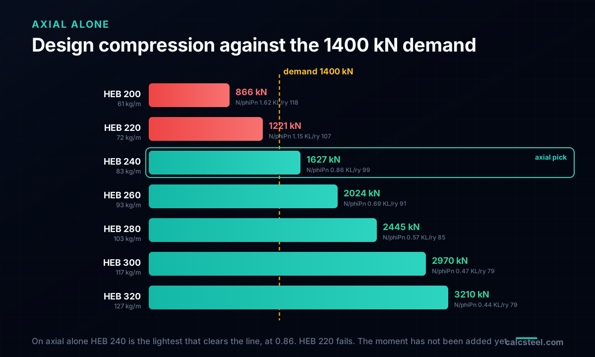
Start the way a lookup does, with the axial load and nothing else. AISC 360 Chapter E gives the design compression from the slenderness. With K = 1 and the 6.0 m storey, the minor-axis slenderness KL over ry runs from 118.5 for the HEB 200 down to 84.7 for the HEB 280. Feed that through the column curve and you get the buckling stress Fcr, then multiply by the area and the 0.90 factor for the design compression phiPn:
- HEB 220: slenderness 107.4, phiPn = 1221 kN. Against the 1400 kN demand that is a utilisation of 1.15, a fail.
- HEB 240: slenderness 98.7, Fcr = 170.6 MPa, phiPn = 1627 kN. Utilisation 1400 / 1627 = 0.86, a comfortable pass.
So on axial alone the answer is HEB 240. It is the lightest section in the list that carries the 1400 kN, and at 0.86 it has real headroom, about 14 percent. A capacity table, or a column calculator run with axial only, would hand you the HEB 240 and you would move on. Notice how much the 6 m did here already: the HEB 240 is a stocky 84 kg/m section, and the storey height has spent most of it, leaving only that 14 percent. That thin margin is all the axial check knows about. It has never seen the moment.
Add the moment, and the interaction sinks the HEB 240
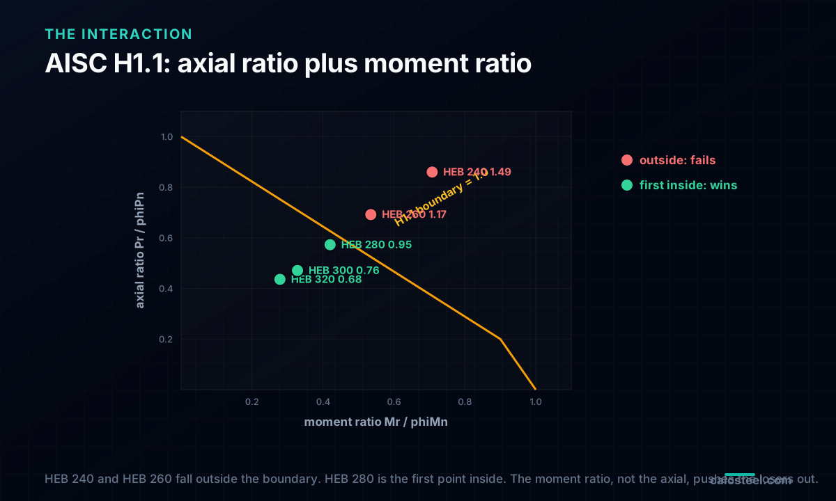
Now let the moment into the room. A beam-column is checked by the AISC 360 H1.1 interaction equation, which adds the axial utilisation and the bending utilisation into one ratio that must stay at or below 1.0. When the axial utilisation is 0.2 or more, the rule is:
IR = Pr/Pc + (8/9)(Mr/Mc)
where Pr/Pc is the axial ratio we already have and Mr/Mc is the moment ratio. The moment capacity Mc = phiMn is where the 6 m bites a second time. The HEB 240 could reach a design plastic moment of 324.6 kN.m if its flange were braced, but over a 6 m unbraced length lateral-torsional buckling drops it to phiMn = 275.9 kN.m, a 15 percent knockdown. The moment demand is not the bare 150 kN.m either: the second-order amplifier lifts it to 195.3 kN.m (the next section explains why). Put the pieces together for the HEB 240:
IR = 0.86 + (8/9)(195.3 / 275.9) = 0.86 + 0.63 = 1.49
The section that passed the axial check at 0.86 fails the combined check at 1.49, nearly 50 percent over. And it is not alone. Step up one size to the HEB 260, and the axial ratio eases to 0.69 but the interaction is still 1.17, a fail. The moment has eliminated the two lightest sections that carry the axial. The lookup answer is gone.
Why the moment grows: the second-order amplifier
The 150 kN.m is the first-order moment, the one a linear analysis draws. But the axial load does not act on the undeflected column, it acts on the column that has already bent sideways under the moment, and that offset multiplied by the 1400 kN adds moment the first-order diagram never showed. AISC 360 captures this member effect with the B1 amplifier:
B1 = Cm / (1 - Pr/Pe1) ≥ 1
where Pe1 is the elastic buckling load of the member about the axis of bending. For the HEB 240, Pe1 = 6033 kN, so with Cm = 1.0 the amplifier is 1 / (1 - 1400/6033) = 1.30, turning the 150 kN.m into 195.3 kN.m. For the stiffer HEB 280, Pe1 = 10307 kN and B1 = 1.16, a smaller amplification of the same 150 kN.m to 173.6 kN.m, because a stiffer column deflects less and feeds itself less second-order moment.
This is the quiet reason a beam-column is harder than the sum of its parts. The heavier section is not just carrying more, it is amplifying less. The B1 factor rewards stiffness twice: once in the capacity and once in the demand. On this column it accounts for a third of the moment that fails the HEB 240.
The winner: HEB 280, and the scorecard that names it
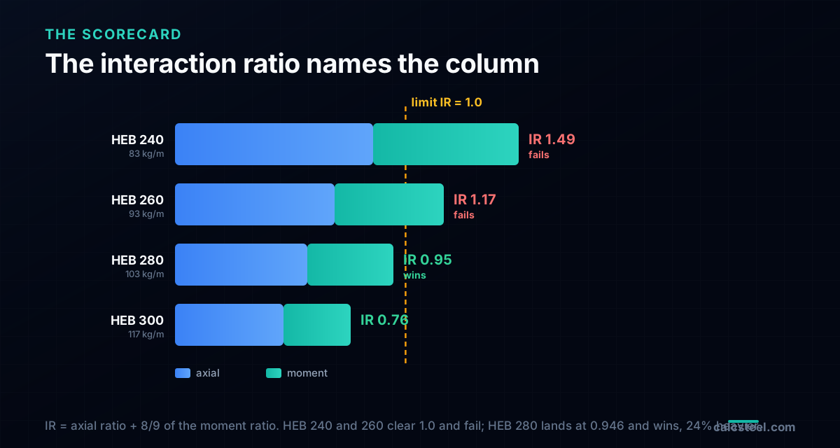
Keep stepping up. The HEB 280 brings a design compression of phiPn = 2445 kN and, after the same 6 m lateral-torsional knockdown, a design moment of phiMn = 413.3 kN.m. Its axial ratio is a relaxed 1400 / 2445 = 0.573, its amplified moment is 173.6 kN.m, and the interaction lands at:
IR = 0.573 + (8/9)(173.6 / 413.3) = 0.573 + 0.373 = 0.946
That is a pass, with a little room. The HEB 280 is the lightest section in the list that carries the axial and the moment together over 6 m. Here is the whole contest on one card:
| Section | kg/m | Axial ratio | Moment ratio | IR (H1.1) | Verdict |
|---|---|---|---|---|---|
| HEB 240 | 83.2 | 0.86 | 0.71 | 1.49 | Fails |
| HEB 260 | 93.0 | 0.69 | 0.53 | 1.17 | Fails |
| HEB 280 | 103.1 | 0.57 | 0.42 | 0.946 | Wins |
| HEB 300 | 117.0 | 0.47 | 0.33 | 0.76 | Passes |
The number that decides is the last column, and it is nothing like the axial ratio. Sizing on axial alone stopped at the HEB 240, 83.2 kg/m. The interaction forces the HEB 280, 103.1 kg/m. That is 24 percent more steel down every column in the grid, bought not by the axial load a table would look up but by the moment and the 6 m length that a table never sees.
Why a stronger steel would not save the HEB 240
The tempting shortcut, when a section fails, is to reach for a higher grade. If S355 will not do it, surely S460 will. Run the counterfactual: take the failing HEB 240, keep the geometry, and lift the yield from 355 to 460 MPa. The results are a lesson in what actually controls a 6 m column.
- The design compression rises from 1627 kN to only 1696 kN, a 4 percent gain. At a slenderness of 98.7 the column is buckling, not yielding, and buckling depends on stiffness and length, not on yield strength. A stronger steel barely moves the compression capacity, because the column fails by going unstable long before the steel reaches 460 MPa.
- The design moment rises more, from 275.9 to 331.1 kN.m, because bending capacity does scale with yield. But it is not enough.
- The interaction ratio falls from 1.49 to 1.35. Still a fail.
So the S460 HEB 240 still does not carry the pair, and you have paid for a premium steel to move from 1.49 to 1.35. This mirrors the deflection lesson on long-span beams, where a stronger steel does nothing for stiffness. Here a stronger steel does almost nothing for buckling. The levers that work are geometric: a bigger section (more area and more ry, which is what the HEB 280 buys), a shorter unbraced length (brace the minor axis at mid-height and the slenderness halves), or a smaller moment (detail the beam connection to shed the unbalanced moment). Steel grade is not on that list.
What the codes ask, on three continents
The worked check above is AISC 360, but every major code frames a beam-column the same way: a design compression from a buckling curve, a design moment reduced for lateral-torsional buckling, a second-order moment, and one interaction inequality that must not exceed unity.
- AISC 360 (United States), the H1.1 equations used here, with the compression from Chapter E, the flexure from Chapter F, and the B1/B2 amplifiers or a direct second-order analysis for the moment.
- Eurocode 3, EN 1993-1-1 (Europe), clause 6.3.3, with the two interaction expressions and the interaction factors kyy and kzz. The buckling reduction factor chi replaces the AISC column curve, and the moment is reduced by chiLT for lateral-torsional buckling. The bones are identical: axial term plus moment term, at or below 1.0.
- ABNT NBR 8800 (Brazil), the interaction of clause 5.5, closely aligned with the AISC form: an axial ratio plus a moment ratio, with the split at 0.2 and the same 8/9 weighting on the bending term.
The numbers shift a few percent between codes, but the verdict does not. On any of the three, the HEB 240 fails the pair over a 6 m storey and the section climbs. The interaction equation is the universal language of the beam-column, and the axial-only lookup is not.
Common mistakes and FAQ
"The column carries axial, so I sized it for axial." This is the mistake the whole article is built to catch. A storey column almost always carries a moment too, from an unbalanced beam, from frame action, from a notional load, and the moment runs through the interaction with the axial. Size for the pair, not the larger of the two.
"I used the plastic moment for bending capacity." Only valid if the compression flange is braced within the length where the plastic moment is reachable, about 2.5 to 3.2 m for these HEB sections. Over a 6 m storey braced only at the floors, lateral-torsional buckling reduces the moment capacity, here by 15 percent on the HEB 240. Forgetting it is unconservative on exactly the check that governs.
"I used the first-order moment." The axial load riding on the deflected shape adds second-order moment. On this column the B1 amplifier lifts the 150 kN.m by 16 to 30 percent depending on the section. Either apply the amplifier or run a proper second-order analysis; do not check a beam-column with the linear moment.
"Does K = 1 always apply?" Only in a braced frame, where the storey cannot sway. In an unbraced (moment) frame K exceeds 1, often well above 2, the buckling length grows, and the compression capacity falls further. Modern practice sidesteps the K debate with the direct analysis method, which uses K = 1 with reduced stiffnesses and notional loads instead.
"Which axis buckles?" For a doubly symmetric HEB with equal unbraced lengths, the minor axis, because ry is smaller than rx. That is why ry sets the compression capacity in the table above. Brace the minor axis and the game changes.
From a storey height to the governing check
The question was "what column for a 6 m storey height", and the honest answer is that the height alone cannot answer it. Feed the column its real demand, 1400 kN of axial and 150 kN.m of moment, and the 6 m storey turns out to be the variable that discounts both capacities at once: the buckling length in compression and the unbraced length in bending. The section that carries the axial, the HEB 240, fails the interaction at 1.49. The section you build, the HEB 280, is 24 percent heavier, and a stronger steel cannot close the gap.
That is the difference between a lookup and a check. A table reads the axial load and hands you a section. The interaction reads the axial, the moment, the storey height and the second-order amplification, and hands you the column that actually stands up. You can run the axial half yourself in the calculator above, and the full beam-column check, section by section, in the CalcSteel editor, free and with no login, and free for students. Put in your own storey height and your own moment, and watch which check governs.
Sources
- 1.AISC 360, Specification for Structural Steel Buildings (Chapter E compression, Chapter F flexure, Chapter H combined forces, Appendix 8 second-order analysis)
- 2.EN 1993-1-1, Eurocode 3: Design of steel structures, Part 1-1 (clause 6.3.3, members in combined bending and axial compression)
- 3.ABNT NBR 8800, Projeto de estruturas de aco e de estruturas mistas de aco e concreto de edificios (barras submetidas a forca axial e momento fletor)
- 4.ASCE 7, Minimum Design Loads and Associated Criteria for Buildings and Other Structures (load combinations, notional loads)
- 5.AISC Steel Construction Manual, beam-column design tables and the effective length discussion
Try CalcSteel for free
Model, analyze and design steel structures in your browser. No install, no signup.
Open the 3D editor