Thermal Expansion of Steel: How Much It Moves in Summer
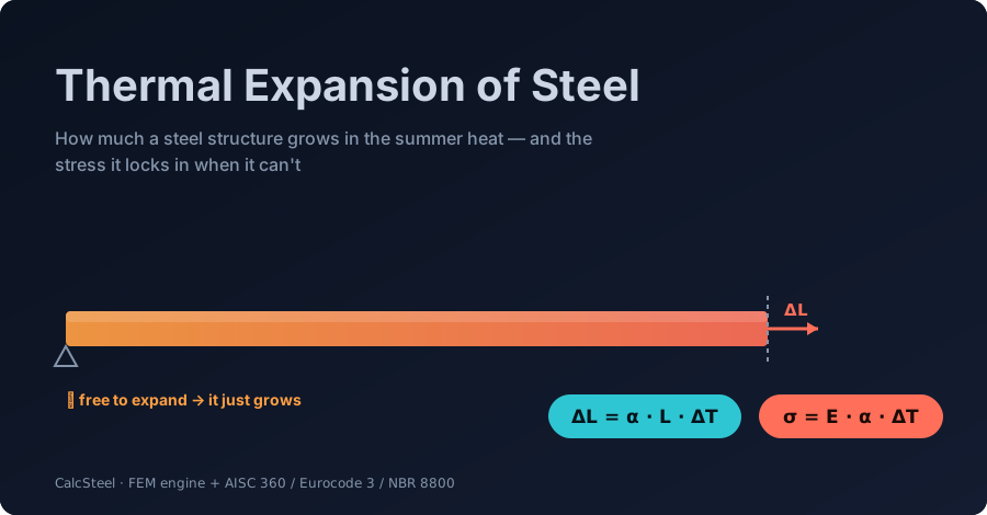
How much does a steel structure grow in the summer heat — and what happens when it can't? A complete, worked guide to thermal expansion of steel, from ΔL = αLΔT to the restrained stress σ = EαΔT, every number computed by a real FEM engine and a free live calculator you can drive yourself.
Key takeaways
- Steel expands about 12 × 10⁻⁶ per °C (Eurocode 3) — 6.5 × 10⁻⁶ per °F in AISC. A 6 m member gains 2.16 mm for a +30 °C summer rise; a 30 m span gains 12.6 mm.
- Free to move, thermal expansion creates ZERO stress — it is only when you restrain the movement that force appears.
- Restrained thermal stress is σ = E·α·ΔT, and it is independent of length and section area: +40 °C locks in 96 MPa in any steel member — 38% of MR250 yield, before a single load is applied.
- The free thermal force N = E·A·α·ΔT is large (451 kN for an IPE 330 at +30 °C), but how much of it a real structure actually carries depends on how stiff its restraint is — pure FEM territory.
- A flexible frame lets the beam expand almost freely; a braced bay still funnels tens of kN into its diagonals; a rigidly locked member takes the full force. That spread is why long steel buildings are split by expansion joints.
Why a steel frame is never the same size twice
On a still July afternoon the steel roof of a warehouse can sit 20–30 °C hotter than the air around it — dark steel in direct sun routinely passes 50 °C, and railway engineers measure rails hotter still. Every one of those members is quietly getting longer. In the summer of 2026, Union Pacific began painting its rails white for exactly this reason: to shave a few degrees off the steel and hold back the heat-driven buckling railroaders call a sun kink.
Thermal expansion is the most universal load a structure ever sees, and the only one that acts even when nothing is standing on it. Ignore it and you get jammed expansion joints, cracked cladding, bowed rails, and — when a member is fully restrained — locked-in stresses large enough to matter next to the loads you actually designed for.
This guide is the complete, worked walkthrough. We start from the one equation every engineer memorises, ΔL = α·L·ΔT, and go all the way to a braced steel bay where the summer heat has nowhere to go and only a finite-element solver can tell you where the force ends up. Every number here was computed by the CalcSteel FEM engine and checked against closed-form theory to three decimals, and there is a free beam calculator embedded partway down so you can model a member yourself.
Whether you are a student meeting α for the first time, a practising engineer spacing expansion joints, or just curious why bridges have those zig-zag gaps, this is written for you.

The coefficient of thermal expansion of steel
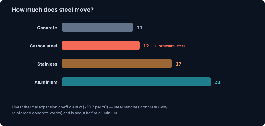
Every material has a coefficient of linear thermal expansion, α — the fractional change in length per degree of temperature change. For structural carbon steel it is almost exactly α = 12 × 10⁻⁶ per °C, the value Eurocode 3 (EN 1993-1-1, §3.2.6) tells you to use for temperatures up to about 100 °C.
In imperial units the American code writes the same property as α = 6.5 × 10⁻⁶ per °F (AISC), which is ≈ 11.7 × 10⁻⁶ per °C — the small difference is unit rounding, not physics. Either way, the number is tiny: heat a steel bar by one degree and it grows by twelve parts in a million. What makes it matter is that real structures are long and real temperature swings are large, and the two multiply.
Steel's α is worth committing to memory in context:
- Concrete ≈ 10–12 × 10⁻⁶/°C — practically the same as steel. That is not a coincidence we are lucky to have; it is why reinforced concrete works at all. If steel and concrete expanded at very different rates, every temperature change would shear the bond between rebar and concrete apart.
- Stainless steel ≈ 16–17 × 10⁻⁶/°C — austenitic grades move about 40% more than carbon steel, which matters for mixed-metal details.
- Aluminium ≈ 23 × 10⁻⁶/°C — nearly double steel. An aluminium façade on a steel frame will always try to move faster than what it is bolted to.
One caution: α itself drifts upward at high temperature. The 12 × 10⁻⁶ figure is for ordinary service and summer conditions. In a fire, above ~700 °C, steel's expansion accelerates sharply and the Eurocode gives a full temperature-dependent curve — a different problem from the summer heat this article is about.
Free expansion: ΔL = α·L·ΔT (worked, engine-verified)
When a steel member is free to move — one end fixed, the other able to slide — heat produces pure elongation and no stress at all. The change in length is the coefficient times the original length times the temperature change:
ΔL = α · L · ΔT
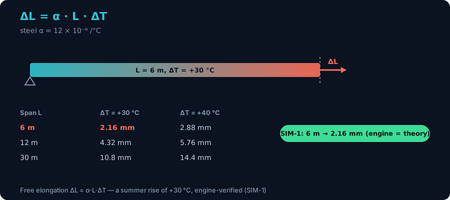
Take a realistic summer case: a 6 m steel beam that rises ΔT = +30 °C from a mild installation temperature to a hot afternoon. Plug in α = 12 × 10⁻⁶/°C:
ΔL = 12 × 10⁻⁶ × 6000 mm × 30 = 2.16 mm.
Just over two millimetres — small, but not nothing when it is trying to push through a connection detailed with no gap. We modelled exactly this beam in the CalcSteel engine, applying the temperature rise as an equivalent thermal load, and it returned an end movement of 2.160 mm with zero internal stress — an exact match to the hand calculation, and the correct physics: unrestrained expansion is stress-free.
Because ΔL scales linearly with length, longer members move proportionally more:
- 6 m at +30 °C → 2.16 mm; at +40 °C → 2.88 mm
- 12 m at +30 °C → 4.32 mm; at +40 °C → 5.76 mm
- 30 m at +30 °C → 10.8 mm; at +40 °C → 14.4 mm
This is the number that sizes an expansion joint or a slotted-hole connection. It is also the friendly half of the story — nothing here threatens the steel. The trouble starts the moment you stop it from moving.
Restrain it and stress appears: σ = E·α·ΔT
Now hold both ends. The steel still wants to expand by α·L·ΔT, but it cannot — so instead of strain, the temperature change turns into stress. Prevent the free thermal strain ε = α·ΔT and, by Hooke's law, you generate a stress equal to Young's modulus times that suppressed strain:
σ = E · α · ΔT
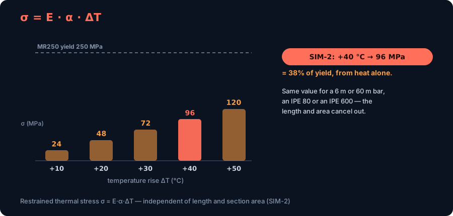
Look closely at what dropped out of that equation: the length and the cross-section area are both gone. A fully restrained thermal stress is the same in a 6 m bar and a 60 m bar, in an IPE 80 and an IPE 600. It depends only on the material (E, α) and the temperature change — one of the most counter-intuitive and important facts in structural behaviour.
For steel with E = 200 GPa and a summer ΔT = +40 °C:
σ = 200,000 MPa × 12 × 10⁻⁶ × 40 = 96 MPa of compression.
We ran a fully restrained IPE 330 through the CalcSteel engine at +40 °C. It returned a support reaction — the thermal force — of 601.0 kN, which over the 62.6 cm² section is exactly 96.0 MPa, matching σ = EαΔT to three decimals. Put that next to MR250 steel's 250 MPa yield and the point lands hard: a 40 °C summer rise, with no load on the structure at all, has already used up 38% of the material's capacity. Add gravity and wind on top and a member that looked comfortable can be much closer to the edge than its load diagram suggests.
The force itself, N = E·A·α·ΔT, does grow with area — 601 kN here — which is why it can crush bearings, shear anchor bolts and buckle slender members (the rail sun kink is exactly this compression finding release sideways). But the stress, the thing that decides whether the steel yields, is fixed by σ = EαΔT alone.
Try it: model the member that carries both load and heat
Thermal stress never acts alone — it rides on top of the bending and shear a member already carries. The fastest way to feel that is to model a real beam and watch its stresses, then remember that a restrained summer rise quietly adds up to 96 MPa on top of whatever you see here.
The calculator below is the real, free CalcSteel beam calculator, embedded right on this page. Set a span, choose supports, add a distributed or point load, and it draws the reactions, the shear and bending moment diagrams and the deflection — instantly, with no login for the math. Size the section until the bending stress is comfortable, then ask yourself how much margin is left for a 96 MPa thermal contribution if that member is restrained.
It is unlimited and genuinely free. When you are ready to combine gravity, wind and thermal restraint on a whole frame — where the interaction is an axial-plus-bending check, not bending alone — that is what the full CalcSteel editor is for.
Max moment
45 kN·m
Max shear
30 kN
Max deflection
10.55 mm
= L/569
Bending stress σ
84.4 MPa
σ = M/Sx
Utilization
44.0%
NBR 8800 · δ ≤ L/250
Geometry & supports
Section
Ix 7999 cm⁴ · Sx 533 cm³ · 42.2 kg/m
Point loads (↓ positive)
None — add as many as you need.
Distributed loads (uniform or trapezoidal)
Model sketch
Diagrams — free PNG / SVG / CSV export, no watermark
Step-by-step — the calculation memory of YOUR beam
IPE 300 · L = 6 m · fy = 250 MPa
1. Reactions (equilibrium of the solved FEM model)
ΣFy = 0 · ΣM = 0
R_A = 30 kN · R_B = 30 kN
2. Peak shear (read from the SFD)
Vmax = |V(x)|max
Vmax = -30 kN @ x = 6 m
3. Peak moment (read from the BMD)
Mmax = |M(x)|max
Mmax = 45 kN·m @ x = 3 m
4. Peak deflection
EI = 15998 kN·m² (E = 200 GPa)
δmax = 10.55 mm @ x = 3 m = L/569
5. Elastic bending stress
σ = Mmax / Sx = 45.00 × 10³ / 533.3
σ = 84.4 MPa
6. Bending check — both codes, side by side
NBR 8800: σ ≤ fy/1.10 = 227.3 MPa · AISC 360: σ ≤ 0.90·fy = 225 MPa
NBR 37.1% PASS · AISC 37.5% PASS
7. Deflection check (serviceability — code-independent)
δ ≤ L/250 = 24 mm
10.55 mm / 24 mm = 44.0% PASS
Recomputed live from the current inputs by the direct-stiffness FEM engine — change any load and every step updates. Reproduce it by hand with the formulas in the sections below.
Lightest catalog profiles that pass (974 flexural candidates · NBR 8800)
| Profile | Std | Weight | Total steel | σ util | δ util | |
|---|---|---|---|---|---|---|
| W310x21 | AISC | 21 kg/m | 126 kg | 83% | 98% | |
| VS 300x23 | BR | 22.6 kg/m | 136 kg | 71% | 84% | |
| U 300x90x6.3 | BR | 23.1 kg/m | 139 kg | 82% | 98% | |
| U 300x100x6.3 | BR | 24.1 kg/m | 145 kg | 77% | 91% | |
| VS 250x25 | BR | 24.6 kg/m | 148 kg | 70% | 100% |
Elastic bending (σ = M/Sx vs fy/γa1, γa1 = 1.10 — NBR 8800) + deflection screening of the full flexural catalog. Lateral-torsional buckling, shear and local buckling are NOT checked here — run the full NBR 8800 / AISC 360 verification in the 3D editor.
Long spans, expansion joints and the sun kink
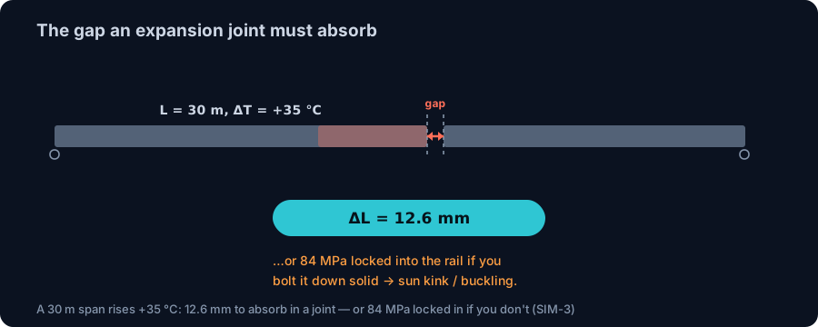
Length is the multiplier that turns a tiny coefficient into a real detailing problem. Take a 30 m crane rail or bridge girder — a modest span in industrial steel — through a ΔT = +35 °C day-to-afternoon swing. The CalcSteel engine, and the hand formula, both give:
ΔL = 12 × 10⁻⁶ × 30,000 mm × 35 = 12.6 mm.
That is the gap an expansion joint has to open and close, every single day, for the life of the structure. Detail it with no gap and you are back to the restrained case — locking in 84 MPa (σ = EαΔT at +35 °C) plus a compressive force big enough to buckle the member sideways. On continuous welded rail this sideways release has a name and a body count: the sun kink, where a hot rail with nowhere to grow snaps into a lateral wave and derails trains. It is a buckling failure driven entirely by suppressed thermal expansion, and it is why track is laid at a controlled "neutral temperature" and why railroads now paint rails white.
The design response is one of two philosophies, and real structures use both:
- Release the movement. Break long buildings into segments with expansion joints (a common rule of thumb is roughly every 40–60 m of steel framing, tuned to climate and code), and let bridges slide on sliding bearings or roll on rockers. Movement without restraint means no stress.
- Restrain the movement and design for the force. Where a joint is impractical, you accept σ = EαΔT and the force N = EAαΔT and check that the members, connections and anchors can carry them alongside the other actions.
Choosing well needs a number for how much force restraint actually attracts — which brings us to the case only a solver can answer.
The climax: where does the thermal force actually go?
Real structures live between the two extremes we have drawn — never perfectly free, never perfectly rigid. When a beam heats up inside a frame, how much of the free thermal force N = E·A·α·ΔT actually develops depends on how stiffly the rest of the structure fights the movement. There is no closed-form formula for it; the force splits according to relative stiffness, and that is precisely what a finite-element solver is for.
Take the IPE 330 beam again — its free thermal force at ΔT = +30 °C is 451 kN — and drop it into three different structures:
- A bare portal frame (slender columns, pinned to sway). The columns are hundreds of times more flexible sideways than the beam is stiff along its axis, so they simply lean outward and the beam expands almost freely: near-zero thermal force, ~2 mm of eave sway. Moment frames are naturally forgiving of heat.
- A rigidly locked member (the restrained case from earlier). The full 451 kN / 96-MPa-class force develops. This is the upper bound.
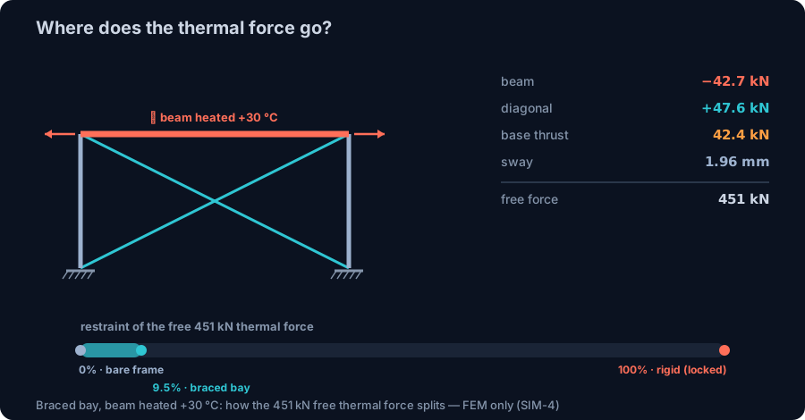
- A braced bay — the realistic middle. We modelled a 12 m × 6 m bay with the beam heated +30 °C and stiff L 100×100×10 diagonals resisting the spread. The CalcSteel engine returns a beam force of only −42.7 kN (9.5% of the free 451 kN) — the frame still moves ~2 mm — but that "small" fraction is +47.6 kN of tension dumped straight into the diagonal bracing and a 42 kN thrust into each foundation, force that no gravity or wind load ever put there.
That is the whole lesson in one experiment. Even stiff bracing restrains only about a tenth of the free thermal force, so the structure keeps moving — but a tenth of 451 kN is still tens of kilonewtons of pure thermal load in the braces and their connections. Multiply a braced bay across a long building with no expansion joint and those forces accumulate. That is why long steel buildings are split into thermally independent blocks. Only an analysis engine can tell you, for your geometry, whether the heat escapes as harmless movement or piles up as force — and where.
Designing for thermal movement in practice
Turning all of this into a safe detail comes down to a handful of decisions, and the codes back each one:
- Pick the temperature range, not a guess. Eurocode EN 1991-1-5 (Thermal actions) gives uniform and gradient temperature components from site climate data; AISC and local practice do the same. The ΔT you design for is the swing from the steel's temperature when it was locked into the structure to its hottest and coldest service states — which is why erection temperature is worth recording.
- Decide release vs restraint, member by member. Slotted holes, sliding bearings and expansion joints release movement and kill the stress; fixed connections restrain it and must then carry σ = EαΔT and N = EAαΔT. Most real buildings mix the two deliberately.
- Watch differential and gradient effects. Sun on one face heats it more than the shaded side; a temperature gradient through a member's depth makes it bow, not just grow. These non-uniform cases have no tidy hand formula and are exactly where a model earns its keep.
- Keep summer and fire separate. The 12 × 10⁻⁶ coefficient and the ~30–50 °C swings here are service-temperature behaviour. Fire is a different regime — hundreds of degrees, a falling elastic modulus and an accelerating α — governed by the structural fire codes, not this article.
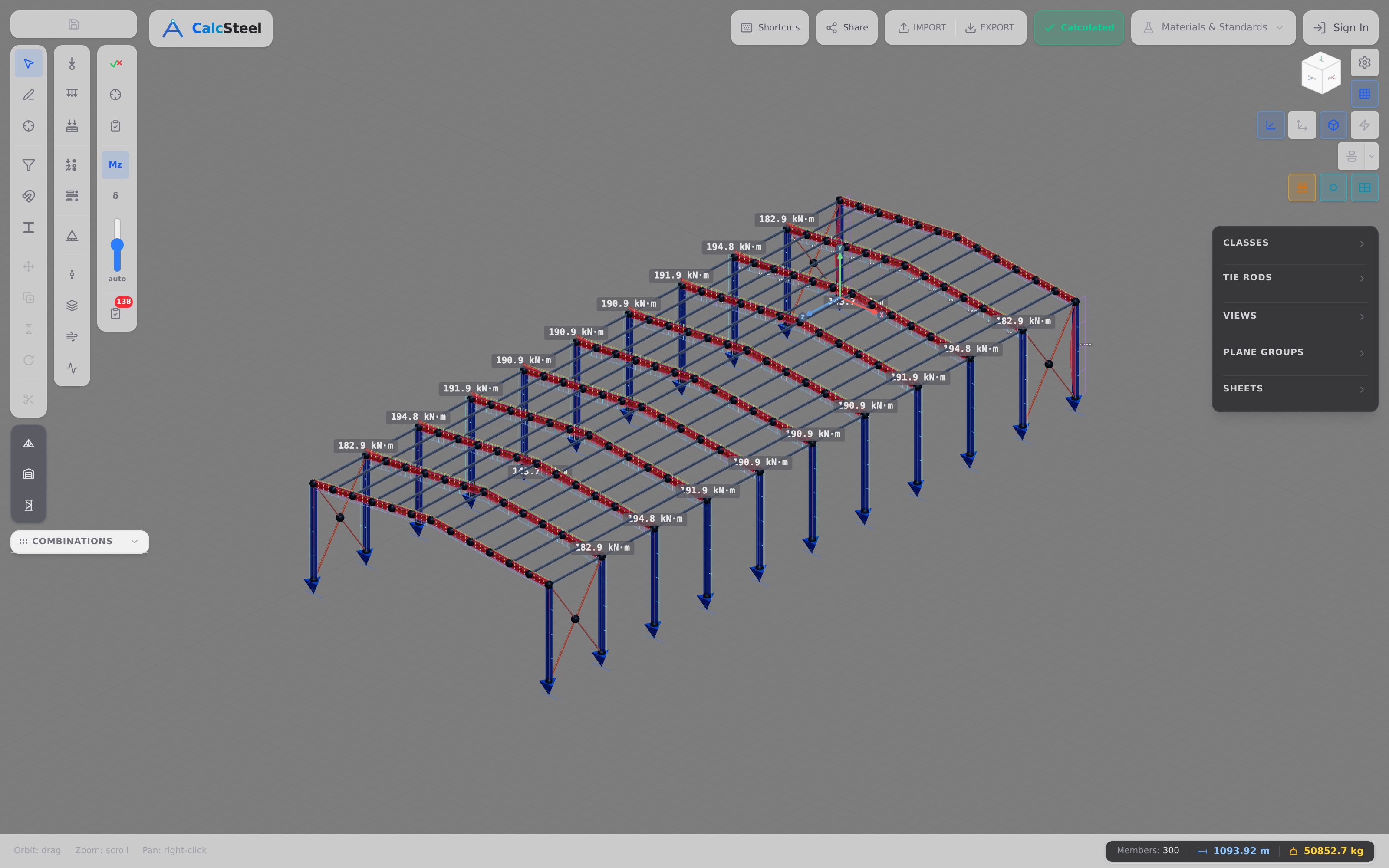
In the CalcSteel editor these choices become model inputs: build the frame, set the restraints, and the same FEM engine that produced every number above resolves how thermal actions combine with gravity and wind, then checks each member to AISC 360, Eurocode 3 or NBR 8800 and colours it by utilisation. You see immediately which members turn the heat into harmless movement and which ones turn it into force.
Common mistakes & FAQ
The physics is short; the misconceptions are stubborn. Run this list before you trust any thermal number.
- Thinking a bigger section expands more, or a longer bar is more stressed. Free elongation ΔL grows with length, but restrained stress σ = EαΔT depends on neither length nor area. A stocky short member and a slender long one lock in the same 96 MPa at +40 °C.
- Assuming steel barely moves. 2 mm on a 6 m beam and 12.6 mm on a 30 m span are enough to jam an ungapped joint, crack cladding or buckle a rail. "Small" strain over a big structure is a real displacement.
- Ignoring restraint stiffness. The same beam heated the same amount can develop anywhere from ~0 to its full 451 kN depending on what holds it — the single biggest driver of the answer, and the one hand methods can't capture.
- Forgetting the erection temperature. ΔT is measured from the temperature at which the structure was locked together, not from 20 °C by default. Weld up a frame on a cold morning and the summer ΔT is larger.
- Confusing summer thermal with fire. They share the coefficient's name and nothing else. Service heat is elastic and reversible; fire is a separate, code-governed limit state.
How much does steel expand per degree?
About 12 × 10⁻⁶ of its length per °C (Eurocode 3), or 6.5 × 10⁻⁶ per °F (AISC). A 10 m member grows roughly 0.12 mm for each degree Celsius of temperature rise.
Does thermal expansion cause stress?
Only if the movement is restrained. A member free to expand grows by ΔL = αLΔT with zero stress. A fully restrained member develops σ = EαΔT instead — 96 MPa in steel for a +40 °C rise — because the suppressed strain is forced back into the material as stress.
Why doesn't the section size change the thermal stress?
Because σ = EαΔT contains no area term. A bigger section attracts a bigger thermal force (N = EAαΔT), but that force is spread over a proportionally bigger area, so the stress is identical. Length cancels for the same reason.
How far apart should expansion joints be?
Far enough that the accumulated ΔL and the restrained force stay manageable — a common rule of thumb is every 40–60 m of steel framing, but the real answer comes from the climate ΔT, the framing stiffness and the governing code, which is why long buildings are modelled rather than tabled.
Key takeaways
Thermal expansion is the load that is always there, and it is governed by two short equations and one big idea about restraint.
- Free movement: ΔL = α·L·ΔT. Steel's α ≈ 12 × 10⁻⁶/°C. A 6 m beam grows 2.16 mm and a 30 m span 12.6 mm in a hot summer — stress-free, as long as it can move.
- Restrained movement: σ = E·α·ΔT. Independent of length and area — +40 °C locks 96 MPa into any steel member, 38% of MR250 yield, before any load.
- The force N = E·A·α·ΔT is real but conditional. How much of it develops depends entirely on restraint stiffness — from ~0 in a flexible frame to the full 451 kN when rigidly locked.
- Bracing attracts thermal force. A braced bay funnelled 47.6 kN of pure thermal tension into its diagonals even while the frame moved freely — the reason long buildings need expansion joints, and a split only FEM can quantify.
Stop guessing and model it. Punch a span and load into the free beam calculator above, or build the whole frame in CalcSteel and let the same real FEM engine behind every number here resolve thermal, gravity and wind together — in your browser, on a genuinely free plan, with AISC 360, Eurocode 3 and NBR 8800 built in. Students get everything unlocked through CalcSteel Education, free.
Sources
Try CalcSteel for free
Model, analyze and design steel structures in your browser. No install, no signup.
Open the 3D editor