Tension Field Action: the Post-Buckling Reserve Inside a Plate Girder Web
On a slender plate girder web, shear buckling is not failure: a diagonal tension field forms and carries load well beyond it. AISC 360 Chapter G turns that post-buckling reserve into a number, here worth +51 percent on a real 8 mm web.
Key takeaways
- A slender plate girder web buckles in shear well below its yield strength, but it does not fail there: a diagonal tension field forms and the panel keeps carrying load. AISC 360 Chapter G gives both numbers.
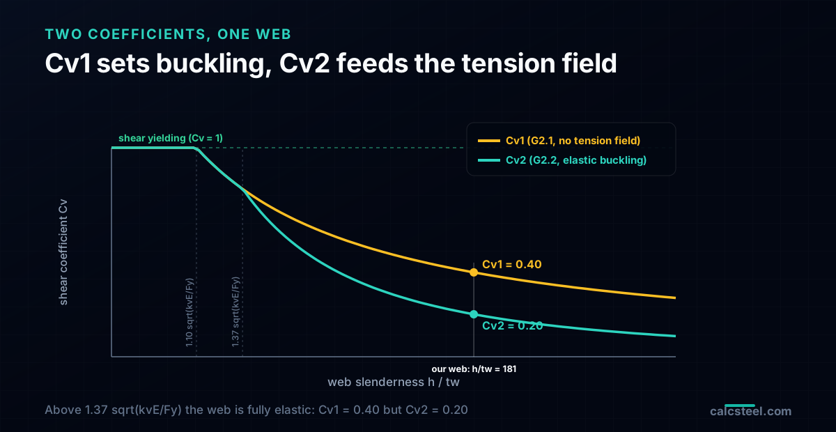
- AISC uses two coefficients. Cv1 (G2.1) is the buckling only strength; Cv2 (G2.2) is the elastic buckling value that seeds the tension field. On our h/tw = 181 web, Cv1 = 0.40 and Cv2 = 0.20.
- On the worked 8 mm web the tension field lifts the design shear from phiVn = 902 kN to 1364 kN, about +51 percent, with nothing added but transverse stiffeners. A 1000 kN interior panel fails without it and passes with it.
- The end panel cannot use tension field action, because the field has no anchor beyond the support. It is designed with Cv1, so the first stiffener usually comes in close (here a = 1000 mm to reach 1287 kN).
- Intermediate stiffeners anchor the field and are sized by a minimum moment of inertia (Chapter G), not by a force. They are a different animal from the bearing stiffeners of J10, even when the plate looks the same.
The web that buckled, and kept working
Open the shear provisions of AISC 360 and you meet a number that looks like a mistake. Take a deep, thin welded web and its shear buckling strength can be less than half of what the same web would carry if it simply yielded. A slender plate girder web buckles early, at a fraction of its shear yield, and a first reading says the panel is finished. It is not. The web keeps carrying shear well past the point where it visibly waves out of plane, and the reserve it hides has a name: tension field action.
This is the mechanism that lets a plate girder use a web only 8 mm thick over a metre and a half of depth. AISC 360 Chapter G puts two different numbers on the same panel: one for the load at which the web buckles, and a larger one for the load it reaches afterwards, once a diagonal tension field forms and the transverse stiffeners anchor it. This guide derives both, computes them on a real welded girder whose shear demand comes straight from the CalcSteel FEM engine, and shows the one place where the reserve is not allowed: the end panel.
What tension field action actually is
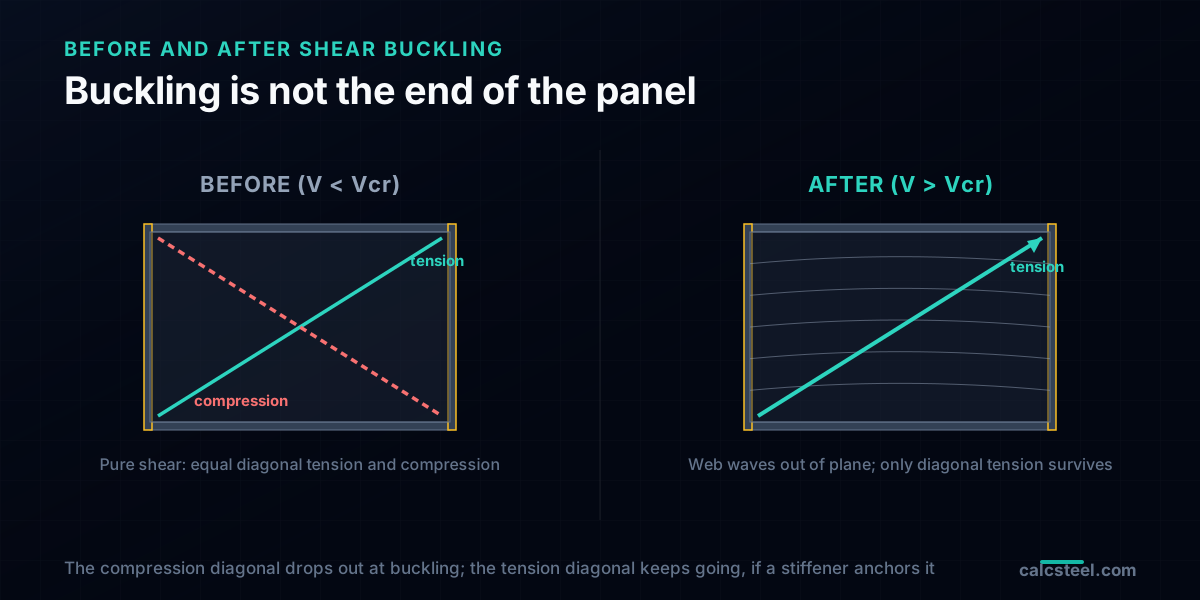
Before it buckles, a web in shear carries load the way any thin plate does: as two equal diagonals, one in tension pulling across one diagonal of the panel, one in compression pushing across the other. Raise the shear and the compression diagonal gives out first, because a thin plate buckles in compression long before it yields. The moment it buckles, that compression diagonal stops picking up any more load.
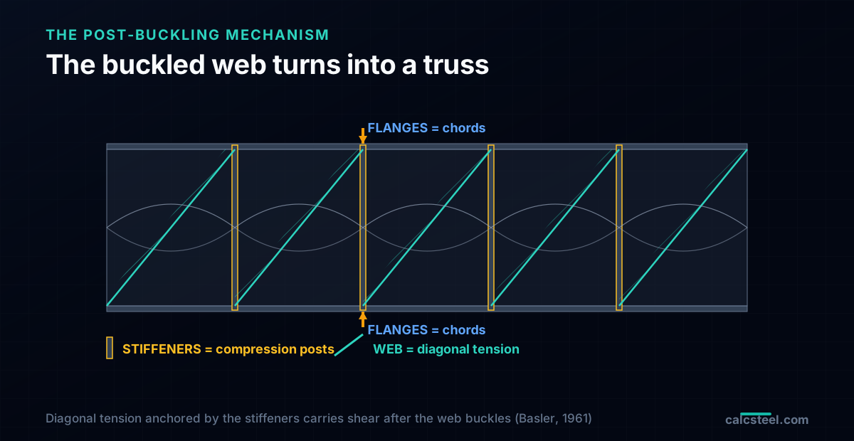
What happens next is the whole story. The tension diagonal does not care that its neighbour has buckled, so it keeps stretching and keeps taking load. But a diagonal pull needs something to pull against. The transverse stiffeners welded across the web become vertical struts that catch the horizontal component of that tension, and the flanges act as the top and bottom chords. The buckled panel has quietly turned into a truss: the web is a field of diagonal ties, the stiffeners are compression posts, and the flanges are the chords. This is the load path Basler described in 1961, and it is why AISC lets you count strength beyond buckling.
Why a slender web buckles in shear first
Shear on a panel is equivalent to equal tension and compression at 45 degrees. The compression diagonal turns the web into a long, thin plate loaded on its edges, and like any such plate it has a critical buckling stress that falls with the square of its slenderness. Push the depth to thickness ratio h/tw high enough and the elastic shear buckling stress drops below the shear yield stress, so the web buckles while it is still elastic, far short of yielding.
AISC captures all of this in a single coefficient, Cv, the ratio of the web shear strength to the shear yield strength 0.6·Fy·Aw. When h/tw is stocky, Cv = 1 and the web yields. As h/tw grows, Cv drops: first through an inelastic transition, then into an elastic branch where it falls off as 1/(h/tw)². Transverse stiffeners raise the plate buckling coefficient kv, because a shorter panel between stiffeners is harder to buckle: kv = 5 + 5/(a/h)², where a is the stiffener spacing and h the clear web depth.
The worked girder, and the shear it has to carry
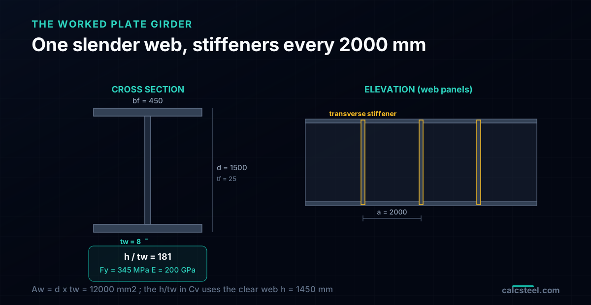
Here is the girder this guide sizes. It is a welded plate girder, overall depth d = 1500 mm, flanges 450 × 25 mm, and a web only tw = 8 mm thick. The steel is Fy = 345 MPa. The clear web depth is h = 1450 mm, so the web slenderness is h/tw = 181, deep into the slender range where shear buckling governs. The shear area is Aw = d·tw = 12 000 mm², and the shear yield reference 0.6·Fy·Aw is 2484 kN.
Note the two depths, because swapping them is a quiet error: the shear area Aw uses the overall depth d, while the slenderness h/tw inside Cv uses the clear web depth h between the flanges.
The demand is not invented. The girder spans 12 m simply supported under a factored line load of 200 kN/m, and the CalcSteel FEM engine returns a support shear of 1200 kN, which matches the statics hand check wL/2 = 200 × 12 / 2 exactly. That 1200 kN at the support, and 1000 kN one metre in at the first interior panel, are the numbers every capacity below has to beat.
Two coefficients on one web: Cv1 and Cv2
AISC 360 does not use one Cv, it uses two, and mixing them up is the most common error in a plate girder shear check. Cv1 is the web shear strength coefficient of Section G2.1: the buckling limited strength with no help from the tension field, taken above its transition as a straight inelastic line, Cv1 = 1.10√(kv·E/Fy) / (h/tw). Cv2 is the web shear buckling coefficient of Section G2.2: the true elastic plate buckling value, which for a slender web drops further, Cv2 = 1.51·kv·E / [(h/tw)²·Fy].
For our panel with stiffeners at a = 2000 mm, a/h = 1.38 and kv = 7.63. The two transition limits are 1.10√(kv·E/Fy) = 73 and 1.37√(kv·E/Fy) = 91. Our web at h/tw = 181 is well above both, firmly in the elastic range:
| Quantity | Value |
|---|---|
| a/h (panel aspect ratio) | 1.38 |
| kv = 5 + 5/(a/h)² | 7.63 |
| Cv1 (G2.1, buckling only) | 0.40 |
| Cv2 (G2.2, seeds the field) | 0.20 |
Cv2 being the lower of the two is not a contradiction. Cv1 is the strength the web reaches on its own. Cv2 is only the starting point of the tension field calculation: it measures how much shear survives pure buckling, and the tension field is then added on top of it.
The reserve, written out
Section G2.2 gives the shear strength of an interior panel that develops a tension field:
Vn = 0.6·Fy·Aw·[ Cv2 + (1 − Cv2) / (1.15√(1 + (a/h)²)) ]
Read the bracket as two pieces. The first term, Cv2, is the shear the buckled web still carries directly. The second term is the tension field itself: the fraction (1 − Cv2) of yield that pure buckling gave up is recovered, discounted by the panel geometry through 1.15√(1 + (a/h)²). A squarer panel (smaller a/h) recovers more, a long panel recovers less, and as a/h grows the second term fades and Vn falls back toward the buckling value.
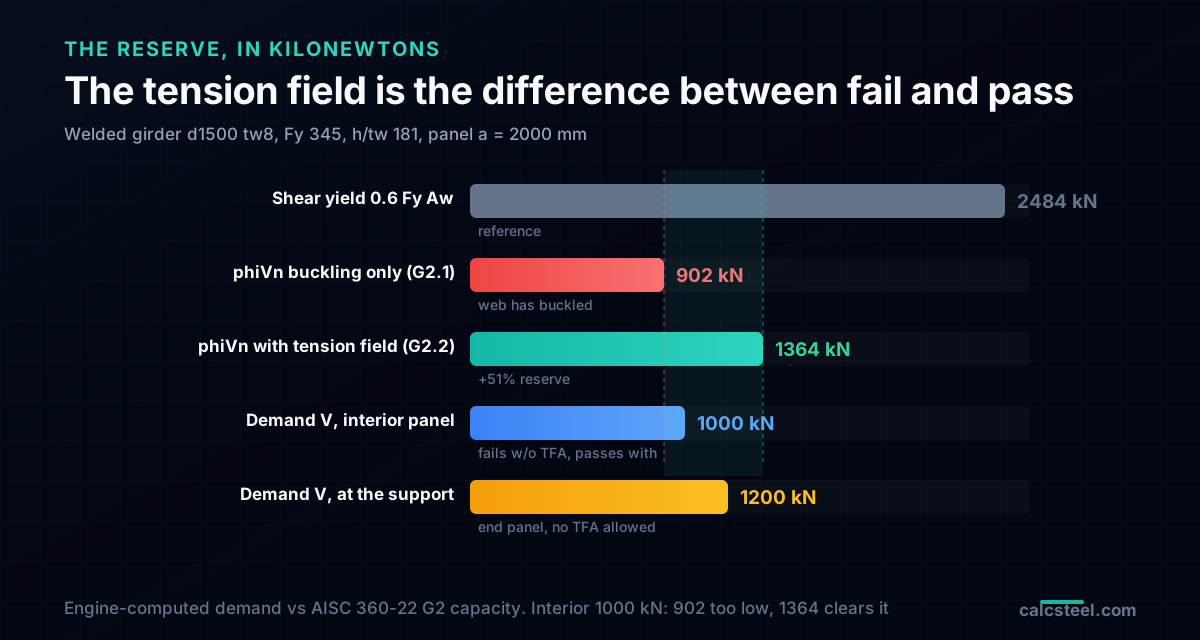
Put the numbers in. With Cv2 = 0.20 and a/h = 1.38, the bracket is 0.20 + (1 − 0.20)/(1.15√(1 + 1.38²)) = 0.61. So Vn = 0.6 × 345 × 12 000 × 0.61 = 1515 kN, and with phi = 0.90 the design strength is phiVn = 1364 kN. The buckling only strength from G2.1 was Vn = 0.6·Fy·Aw·Cv1 = 1003 kN, or phiVn = 902 kN. The tension field has added just over 50 percent to the same 8 mm web, with nothing changed but a row of stiffeners.
Fail without it, pass with it
Now line the demand up against the capacity. One metre in from the support, at the first interior panel, the engine shear is 1000 kN. Check that panel:
| Limit state | phiVn | Verdict at 1000 kN |
|---|---|---|
| Buckling only (G2.1, Cv1) | 902 kN | 1000 > 902, fails |
| Tension field (G2.2) | 1364 kN | 1000 < 1364, passes |
This is the entire case for tension field action in one line. Without it, a real 1000 kN interior panel on this girder fails by nearly 100 kN, and you would be forced into a thicker web across the whole span. With it, the same web passes with room to spare. The reserve is not a rounding bonus, it is the difference between a girder that works and one that does not.
The chart makes the hierarchy plain: the shear yield ceiling is 2484 kN, the web buckles at an effective 902 kN, the tension field lifts it to 1364 kN, and both the 1000 kN interior demand and the 1200 kN support demand sit inside that recovered band.
Try it: get your shear demand first
The Chapter G check only means something once you know the shear the panel actually carries. Tension field action sets the capacity, but the demand comes from the analysis: the shear diagram of your girder under its real load and span. Use the beam calculator below to get the shear at the support and at each stiffener line, then compare it against the phiVn your web and spacing deliver.
Enter your span, supports and loads, read the shear ordinate at the panel you care about, and that is the number that has to be smaller than the phiVn from the equations above. Change the load or the span and watch the shear move: that is the demand side of every plate girder shear check.
Max moment
45 kN·m
Max shear
30 kN
Max deflection
10.55 mm
= L/569
Bending stress σ
84.4 MPa
σ = M/Sx
Utilization
44.0%
NBR 8800 · δ ≤ L/250
Geometry & supports
Section
Ix 7999 cm⁴ · Sx 533 cm³ · 42.2 kg/m
Point loads (↓ positive)
None — add as many as you need.
Distributed loads (uniform or trapezoidal)
Model sketch
Diagrams — free PNG / SVG / CSV export, no watermark
Step-by-step — the calculation memory of YOUR beam
IPE 300 · L = 6 m · fy = 250 MPa
1. Reactions (equilibrium of the solved FEM model)
ΣFy = 0 · ΣM = 0
R_A = 30 kN · R_B = 30 kN
2. Peak shear (read from the SFD)
Vmax = |V(x)|max
Vmax = -30 kN @ x = 6 m
3. Peak moment (read from the BMD)
Mmax = |M(x)|max
Mmax = 45 kN·m @ x = 3 m
4. Peak deflection
EI = 15998 kN·m² (E = 200 GPa)
δmax = 10.55 mm @ x = 3 m = L/569
5. Elastic bending stress
σ = Mmax / Sx = 45.00 × 10³ / 533.3
σ = 84.4 MPa
6. Bending check — both codes, side by side
NBR 8800: σ ≤ fy/1.10 = 227.3 MPa · AISC 360: σ ≤ 0.90·fy = 225 MPa
NBR 37.1% PASS · AISC 37.5% PASS
7. Deflection check (serviceability — code-independent)
δ ≤ L/250 = 24 mm
10.55 mm / 24 mm = 44.0% PASS
Recomputed live from the current inputs by the direct-stiffness FEM engine — change any load and every step updates. Reproduce it by hand with the formulas in the sections below.
Lightest catalog profiles that pass (974 flexural candidates · NBR 8800)
| Profile | Std | Weight | Total steel | σ util | δ util | |
|---|---|---|---|---|---|---|
| W310x21 | AISC | 21 kg/m | 126 kg | 83% | 98% | |
| VS 300x23 | BR | 22.6 kg/m | 136 kg | 71% | 84% | |
| U 300x90x6.3 | BR | 23.1 kg/m | 139 kg | 82% | 98% | |
| U 300x100x6.3 | BR | 24.1 kg/m | 145 kg | 77% | 91% | |
| VS 250x25 | BR | 24.6 kg/m | 148 kg | 70% | 100% |
Elastic bending (σ = M/Sx vs fy/γa1, γa1 = 1.10 — NBR 8800) + deflection screening of the full flexural catalog. Lateral-torsional buckling, shear and local buckling are NOT checked here — run the full NBR 8800 / AISC 360 verification in the 3D editor.
The one place the reserve is not allowed: the end panel
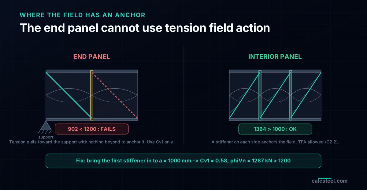
The tension field needs an anchor on both sides. An interior panel has a stiffener to its left and its right, so the diagonal tension has somewhere to land at each end. The end panel, the one between the support and the first stiffener, does not: on the support side there is no adjacent panel to balance the horizontal pull of the tension field. AISC 360 G2.2 therefore forbids tension field action in end panels. They are designed by G2.1 alone, with Cv1.
That is a problem, because the end panel is exactly where the shear is highest. Our support shear is 1200 kN, but the end panel with the 2000 mm spacing is good for only phiVn = 902 kN. It fails by almost 300 kN. The fix is not a thicker web, it is a closer first stiffener. Bring the first stiffener in to a = 1000 mm and the panel aspect ratio drops to a/h = 0.69, which raises kv to 15.5 and Cv1 to 0.58. The end panel now carries phiVn = 1287 kN, comfortably above the 1200 kN it has to hold. Tight end panels on a plate girder are not decoration, they are the direct consequence of this rule.
When you are allowed to count on it
Tension field action is a real load path, but AISC only lets you use it when the panel can actually build the truss. For an interior panel, all of these must hold, or you fall back to a reduced formula or to Cv1 alone:
| Condition | Our girder | Met? |
|---|---|---|
| a/h ≤ 3.0 | 1.38 | yes |
| a/h ≤ (260/(h/tw))² | 1.38 ≤ 2.06 | yes |
| 2Aw/(Afc + Aft) ≤ 2.5 | 1.07 | yes |
| h/bf ≤ 6.0 | 3.22 | yes |
| Not an end panel | interior | yes |
The flange conditions matter more than they look. The term 2Aw/(Afc + Aft) compares the web area to the flange area: if the flanges are too small relative to the web, they cannot act as stiff chords and the tension field cannot anchor into them. Skinny flanges over a fat web are exactly the case where the truss analogy breaks down, and AISC pulls the reserve back when it sees them.
The stiffener that anchors the field is not a bearing stiffener
The stiffeners that make tension field action possible are transverse (intermediate) stiffeners, and their job is stability, not bearing. They divide the web into panels so that kv, and therefore Cv, is high enough, and they anchor the horizontal pull of the tension field. AISC 360 sizes them by a minimum moment of inertia, not by a force: for our panel the required Ist is only about 37 cm⁴, which a modest pair of plates, say 100 × 10 mm each side of the web, exceeds many times over. Stiffness, not strength, is what usually governs an intermediate stiffener.
This is where a plate girder carries two families of stiffener that look alike and do opposite jobs. A bearing stiffener sits under a concentrated load or a reaction and carries that force as a short column, checked by AISC 360 J10. A transverse stiffener anchors the tension field and is checked by Chapter G. The same plate welded in the same place can be one or the other depending on what it is asked to do, and a girder often needs both: bearing stiffeners at the supports and under point loads, intermediate stiffeners in between. Sizing one by the other rule is a classic mistake.
Common mistakes and FAQ
- Using Cv1 where Cv2 belongs. The tension field formula starts from Cv2, the elastic buckling value, not from Cv1. Plugging Cv1 into the G2.2 bracket overstates the reserve.
- Counting tension field action in the end panel. It is not allowed. Design the end panel with Cv1, or bring the first stiffener in close.
- Expecting the reserve on a rolled beam. A stocky rolled W with h/tw below the transition has Cv = 1 already: it yields in shear and there is no post-buckling reserve to recover. Tension field action only pays off on slender webs.
- Ignoring the flange ratio. If 2Aw/(Afc + Aft) exceeds 2.5, the flanges are too light to anchor the field and the full G2.2 reserve is not available.
- Spacing stiffeners too far apart. Beyond a/h = 3.0 the panel behaves as if it were unstiffened, kv falls to 5.34, and both the buckling strength and the tension field shrink.
Key takeaways
- A slender plate girder web buckles in shear well below its yield strength, but it does not fail there: a diagonal tension field forms and the panel keeps carrying load.
- AISC uses two coefficients: Cv1 (G2.1) for the buckling only strength, Cv2 (G2.2) for the elastic value that seeds the tension field. Here Cv1 = 0.40 and Cv2 = 0.20.
- The tension field lifts the design shear from phiVn = 902 kN to 1364 kN, about +51 percent, on the same 8 mm web. A 1000 kN interior panel fails without it and passes with it.
- The end panel cannot use it. Design it with Cv1, and expect the first stiffener to come in close (here a = 1000 mm for 1287 kN).
- Intermediate stiffeners anchor the field and are sized by stiffness, not force. They are not the same as the bearing stiffeners of J10, even when the plate looks identical.
Sources
- 1.AISC 360-22 Specification, Chapter G (G2.1 web shear strength, G2.2 tension field action, G3 transverse stiffeners)
- 2.AISC Steel Construction Manual, Part 3 and the AISC Design Examples (plate girder shear with tension field action)
- 3.Salmon, Johnson and Malhas, Steel Structures: Design and Behavior, Chapter 11 (Plate Girders)
- 4.Basler, K. (1961), Strength of Plate Girders in Shear, Journal of the Structural Division, ASCE
Try CalcSteel for free
Model, analyze and design steel structures in your browser. No install, no signup.
Open the 3D editor