Steel Mono Stringer Staircase: The Criterion Behind the Code, With a Worked Check
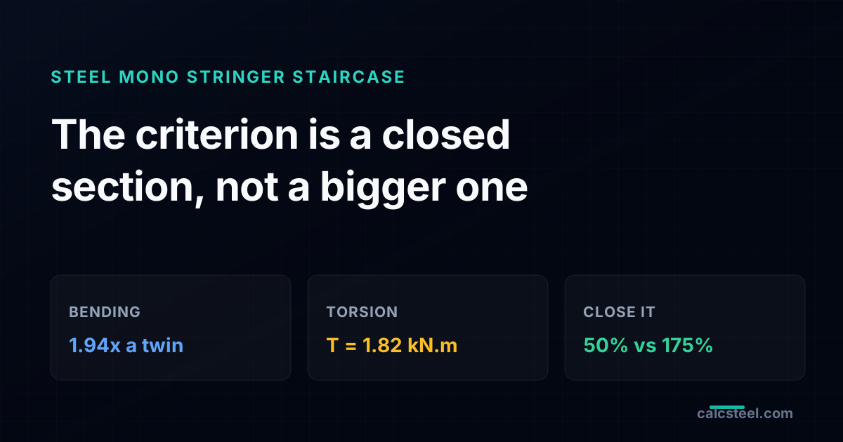
A mono stringer staircase hangs the whole flight on a single central spine, and that one move quietly changes the engineering. The spine carries the full width, so its bending is about double a twin stringer arm, and because the treads cantilever off both sides, any unbalanced live load twists it. Torsion, not just bending, now decides the section. This is the criterion most quick checks miss and the code names anyway: a mono stringer must be a closed section. We size one real public flight end to end on the CalcSteel FEM engine, where the spine carries M = 16.09 kN.m, V = 17.88 kN and a torque T = 1.82 kN.m, and show why a closed RHS 150x100x6 passes the combined check at 50% while an open channel of the same bending strength is torn apart at 175%.
Key takeaways
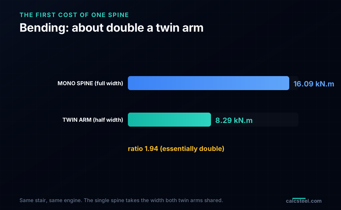
- A mono stringer carries the whole flight on one spine, so its bending demand is about double a twin stringer of the same stair: the worked flight gives M = 16.09 kN.m on the spine against 8.29 kN.m per arm of the twin, a ratio of 1.94.
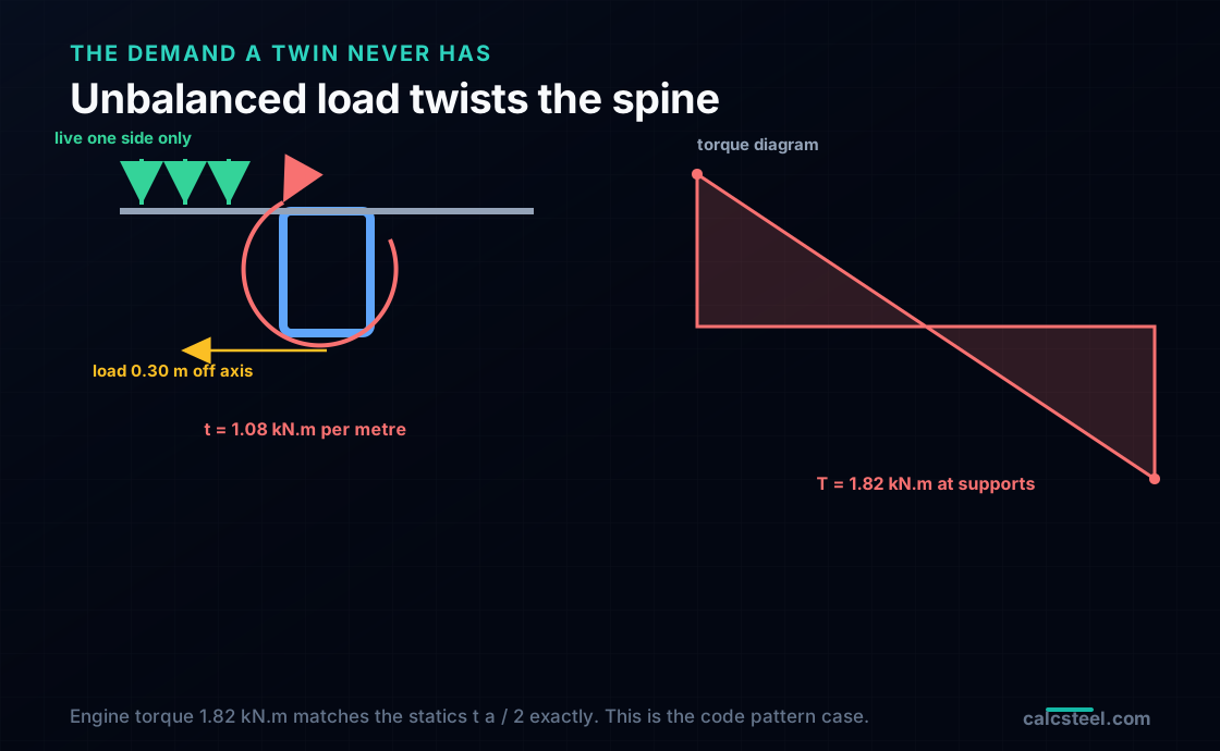
- The treads cantilever off both sides of the spine, so an unbalanced live load (a crowd on one side, the code pattern case) lands off axis and twists the spine. The worked flight develops a distributed torque of 1.08 kN.m per metre and a support torque T = 1.82 kN.m, matched by the engine to the statics exactly.
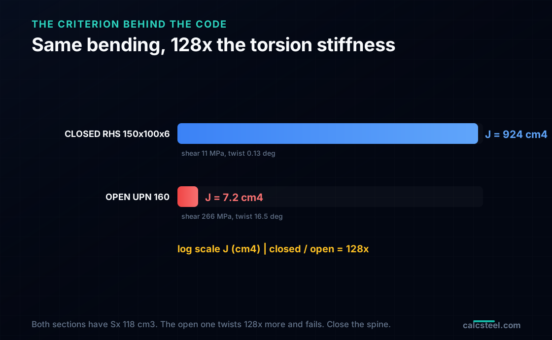
- That torque is why a mono stringer must be a closed section. A closed RHS 150x100x6 has a torsion constant J = 924 cm4; an open channel of the same bending strength (UPN 160, Sx = 118 cm3) has J = 7.2 cm4, about 128 times smaller, and twists 128 times more under the same torque.
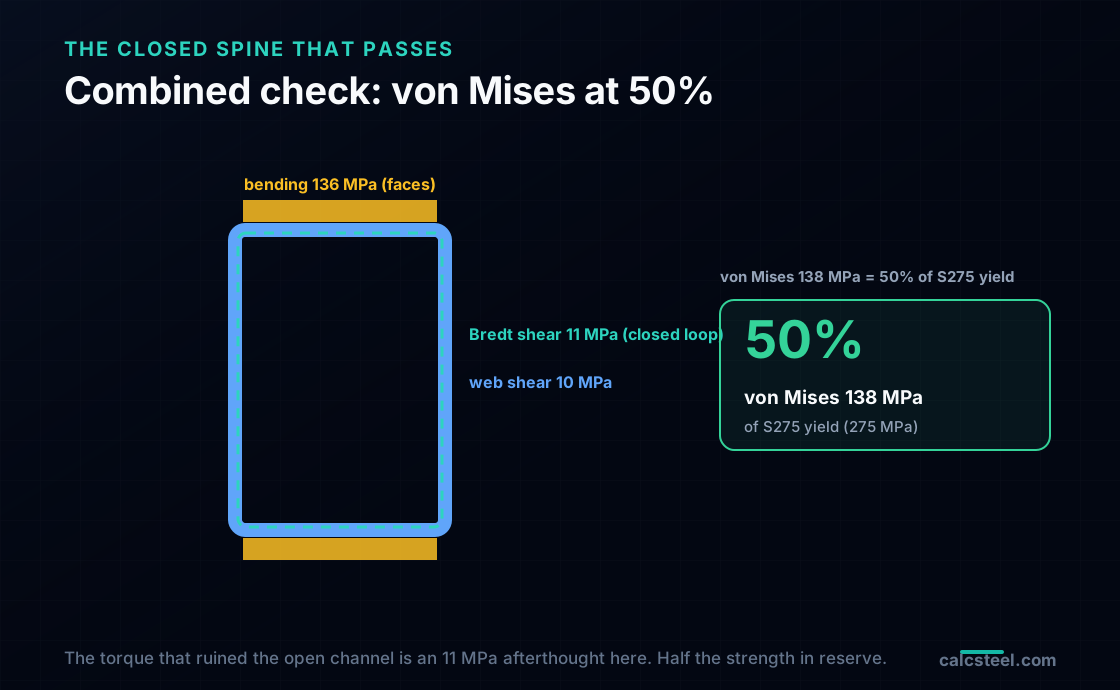
- Worked combined check (S275): the closed RHS 150x100x6 carries bending at 136 MPa, a Bredt torsion shear of 11 MPa and a web shear of 10 MPa, for a von Mises stress of 138 MPa, 50% of yield. The open channel reaches 481 MPa (175%) on bending plus the St Venant torsion shear alone, before any warping stress, and fails.
- The torsion is small in magnitude and catastrophic in the wrong section. The design rule the code carries (AISC 360 H3, EN 1993-1-1 6.2.7) is not a number to chase but a section family to choose: close the spine, and the same little torque that destroys an open channel becomes an 11 MPa afterthought.
One spine, two demands a twin stringer never sees
The mono stringer stair is the one architects reach for when the stair has to look like it is floating: a single steel spine running up the centre of the flight, treads cantilevering out to each side, no structure at the edges to interrupt the line. It is a clean idea, and it hides a specific engineering trap, because that single central beam is asked to do two things at once that a conventional two stringer stair splits and softens.
The first is bending. With one spine instead of two, the whole width of the flight, every tread, every person, lands on that single member. Its bending demand is not a little higher than a twin stringer arm; it is roughly double, because it carries the full width where each twin arm carried half.
The second, and the one that actually catches people, is torsion. The treads reach out from the spine like cantilevers. Load them evenly on both sides and the twists cancel. But codes do not let you assume an even load: a stair has to be checked for a crowd bunched on one side, and the moment the load is unbalanced, it acts off the spine's axis and twists it. A twin stringer never feels this, because its treads span between two supports; a mono stringer feels it on every flight.
Get either wrong and the section is wrong. This guide sizes one real public mono stringer flight from load to combined check, every internal force produced by the CalcSteel finite element engine and hand checked against theory to the decimal. The free CalcSteel beam calculator runs the bending half of it in your browser, and it is embedded halfway down so you can size your own spine as you read.
What a mono stringer is, and how it is modelled
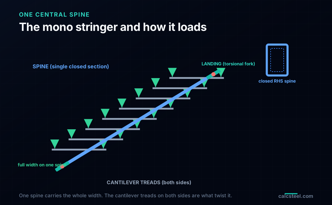
A mono stringer stair carries the flight on a single beam, the spine, running up the centre under the treads, which cantilever out to each side. In steel the spine is almost always a closed section, a rectangular or square hollow section (RHS or box), and each tread is a small cantilever bracket welded to it.
For analysis the spine is the same simply supported inclined beam any stringer is: pinned at the bottom landing, on a roller at the top, free to rotate at both ends, spanning the flight at the stair angle. That much it shares with a twin stringer. Two things make it a different problem.
First, the tributary. A twin stringer takes half the flight width; the mono spine takes all of it. Every load per square metre the code asks for is multiplied by the full width, not half, when it becomes a line load on the spine.
Second, the load path into the spine. On a twin stair the treads span between the two stringers and deliver clean vertical reactions. On a mono stair the treads are cantilevers, and a cantilever delivers its load to the support as a vertical force and a moment. When the two sides are balanced, the moments oppose and cancel; when they are not, the net moment is a torque about the spine's own axis. So the honest model of a mono stringer is a beam in bending and torsion, and both have to be checked together on one section.
The worked flight: geometry and load
We take one straight public flight, floor to floor, and design its spine.
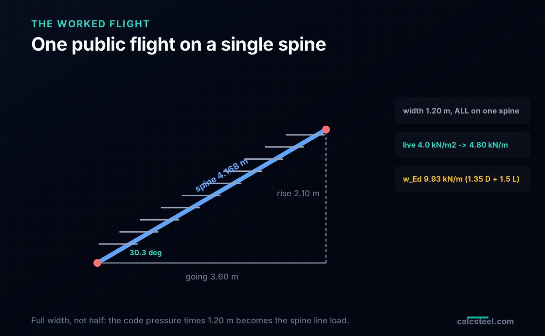
- Going (horizontal run) a = 3.60 m, the distance the stair covers on plan.
- Rise H = 2.10 m, the height it climbs.
- So the angle is theta = arctan(2.10 / 3.60) = 30.3 degrees, cos(theta) = 0.864, a normal, comfortable public slope.
- The inclined length of the spine is s = sqrt(a^2 + H^2) = 4.17 m, the real length of steel.
- The flight is 1.20 m wide, and all of it sits on the one spine. Each tread therefore cantilevers 0.60 m to each side.
The load is a public stair load: a uniform live load of 4.0 kN/m2 on plan (inside the Eurocode category C and NBR public bands, just under the ASCE 7 figure of 4.79) and a dead load of about 1.5 kN/m2 for steel treads, a light finish and a rail allowance. Because the spine carries the whole width, the line loads referred to the horizontal run are the pressure times the full 1.20 m, not half of it:
- Live: wlive = 4.0 kN/m2 x 1.20 m = 4.80 kN/m.
- Dead: wdead = 1.5 x 1.20 + spine self weight (0.22 kN/m) = 2.02 kN/m.
- Factored for strength (EN 1990: 1.35 dead + 1.5 live): wEd = 1.35 x 2.02 + 1.5 x 4.80 = 9.93 kN/m.
Hold that 1.20 m in mind. It is the whole reason a mono spine is a heavier bending member than a twin arm, and the next section shows exactly how much heavier.
The bending: about double a twin stringer
The bending moment of an inclined beam under vertical load equals that of a flat beam spanning the horizontal run, a result that holds for any stringer: the cos(theta) from resolving the load perpendicular to the member and the 1/cos(theta) from the longer inclined span cancel, leaving the flat formula written with the going.
MEd = wEd a2 / 8
For our spine at strength: MEd = 9.93 x 3.602 / 8 = 16.09 kN.m, with a support shear VEd = wEd a / 2 = 17.88 kN. We built the flight on the CalcSteel FEM engine as a simply supported member of span 3.60 m under 9.93 kN/m; it returns M = 16.091 kN.m and V = 17.879 kN, matching the hand formula.
Now the comparison that justifies the whole section choice. Run the same stair as a conventional twin stringer, each of the two members taking half the 1.20 m width. The factored line load per stringer drops to 5.12 kN/m and the engine returns 8.29 kN.m per arm. The mono spine therefore carries 1.94 times the moment of a twin arm, essentially double, exactly as the tributary width predicted. That is the first cost of the single spine, and on bending alone you would already reach for a deeper, heavier section. But bending alone is not the check that decides a mono stringer.
The torsion: where the mono stringer earns its reputation
Here is the demand a twin stringer never has to answer. On a mono stair each tread is a bracket cantilevering out from the spine. The vertical load on that bracket, at its centre of area, sits a real distance to the side of the spine's axis, and a vertical force acting off the axis is a torque. Load both sides equally and the two torques oppose and cancel. The catch is that you are not allowed to assume both sides are loaded equally.
Every loading code requires a stair to be checked for unbalanced and pattern live load, because a real crowd does bunch to one side, on a landing, at a turn, along a rail. The worst realistic case for the spine is the full live load on one 0.60 m cantilever and nothing on the other. That unbalanced half acts at the centroid of its own area, 0.30 m from the spine axis, and its factored line load (1.5 x 4.0 x 0.60) is 3.60 kN/m. The result is a distributed torque along the whole flight:
t = 3.60 kN/m x 0.30 m = 1.08 kN.m per metre
A member torsionally held at both landings (the standard detail, a fork or a moment plate at each end) carries that distributed torque to its ends the same way a beam carries a distributed load, and the support torque is T = t a / 2 = 1.08 x 3.60 / 2 = 1.94 kN.m by statics. On the engine we introduced the torsion the honest way, as the treads do it, by hanging the off centre load on short cantilever brackets welded to the spine rather than by inventing a moment. The engine returns a spine torque of 1.82 kN.m, matching the discretised statics of the applied brackets to the last figure. The torque is real, it is code required, and it is the number the section now has to survive.
The criterion behind the code: open versus closed
Now the torque meets the section, and this is where the choice a mono stringer forces on you becomes stark. Torsion is carried in two completely different ways depending on whether the section is open (a channel, an I, anything you could unroll into a flat strip) or closed (a hollow box or tube). A closed section carries torsion as a smooth shear flow all the way around its perimeter, which is enormously efficient. An open section has no closed loop to flow around, so it resists torsion only by each thin plate twisting on its own, which is feeble. The measure of that efficiency is the torsion constant J, and the gap between the two families is not a percentage, it is orders of magnitude.
Put numbers on it with two sections of the same bending strength. Our closed spine, an RHS 150x100x6, has an elastic modulus Sx = 118 cm3 and a torsion constant J = 924 cm4. An open channel matched to the same bending, a UPN 160 with Sx = 118 cm3, has a torsion constant of just J = 7.2 cm4. The closed section is 128 times stiffer in torsion for the same steel doing the same bending job. Feed the 1.82 kN.m torque into each and the consequence follows directly:
| Closed RHS 150x100x6 | Open UPN 160 | |
|---|---|---|
| Torsion constant J | 924 cm4 | 7.2 cm4 |
| Torsion shear stress | 11 MPa (Bredt) | 266 MPa (St Venant) |
| Free twist over the flight | 0.13 degrees | 16.5 degrees |
| von Mises with bending | 138 MPa (50%) | 481 MPa (175%, fails) |
The open channel does not just fail, it fails by a wide margin, and the 266 MPa is only the St Venant part of its torsion stress; the warping stresses an open channel also develops under this restraint would push it higher still. It would also twist 16.5 degrees over a single flight, which is not a stress problem, it is a stair you cannot walk on. This is the criterion the codes carry, AISC 360 Section H3 for HSS members under torsion and EN 1993-1-1 Section 6.2.7 for combined bending and torsion: it is not really a number to chase, it is a section family to choose. For a mono stringer, close the spine.
Worked combined check: the closed spine that passes
With the section family settled, size the spine and prove it against everything at once. Our RHS 150x100x6 in S275 (fy = 275 MPa) has Sx = 118 cm3, J = 924 cm4 and a wall thickness t = 6 mm. Three stresses act on it under the factored loads, and the code check (EN 1993-1-1 6.2.1, the elastic verification) is to combine them at the worst point and keep the von Mises stress below yield.
- Bending. sigma = MEd / Sx = 16.09 kN.m / 118 cm3 = 136 MPa, largest at the top and bottom faces.
- Torsion shear. A closed section carries torque as a shear flow, and the Bredt formula gives the wall shear as tau = T / (2 Am t), with Am the area enclosed by the wall mid line. For our RHS, Am = 144 x 94 = 13 536 mm2, so tau = 1.82 x 10⁶ / (2 x 13 536 x 6) = 11 MPa, uniform around the perimeter.
- Vertical shear. The two webs carry the 17.88 kN shear, tau = V / (2 h t) = 10 MPa, largest at mid height of the webs.
Combine them where each is worst. At the flange the bending stress meets the torsion shear (the web shear is near zero there): sigmavm = sqrt(1362 + 3 x 112) = 138 MPa. At the web mid height the vertical and torsion shears add on one wall but there is little bending stress: sigmavm = sqrt(3) x (10 + 11) = 37 MPa. The flange point governs at 138 MPa, which is 50% of the 275 MPa yield. The spine passes with half its strength in reserve, and the torque that annihilated the open channel is an 11 MPa contribution here, barely moving the answer. That reserve is deliberate: a stair is a serviceability problem as much as a strength one, and the next section is where the section is actually earned.
Deflection and twist: the serviceability that finishes the job
A stair that passes strength can still be a bad stair. Two movements decide whether the spine feels solid, and the incline changes one of them in a way that catches people out.
Vertical deflection. Unlike the moment, the deflection does not follow the horizontal run. The perpendicular load component acts over the longer inclined length s, and the perpendicular sag then projects back to vertical, and the two cos(theta) factors do not cancel: the real vertical sag is 1/cos(theta) larger than a flat beam of the same run. On the engine the flat model deflects 5.93 mm under the service live load and the true inclined spine 6.87 mm, a ratio of 1.158 that matches 1/cos(30.3 degrees) = 1.158 exactly. Against the common L/360 limit taken on the inclined length s = 4.17 m, the cap is 11.6 mm, so the spine sits at s/607, using 59% of the deflection allowance. Deflection is the tightest of the three checks, which is typical for a stair, but here it still passes.
Twist. The unbalanced torque also rotates the spine, and a mono stringer that twists visibly under a one sided crowd looks alarming even when it is safe. This is the other half of why the section had to be closed. The closed RHS twists just 0.13 degrees over the whole flight under the design torque, imperceptible; the open channel would have twisted 16.5 degrees, a factor of 128 that is simply the ratio of the two torsion constants. The engine's frame model returns the same negligible 0.14 degree twist for the box. With the closed section, twist stops being a design concern; with an open one, it would have been the thing that failed first.
Size your own mono stringer
Reproduce the bending half of this check in the calculator below. Set a simply supported beam, enter the span as your horizontal going a (here 3.60 m), and apply your factored line load wEd as a uniform distributed load. For a mono stringer that line load uses the full flight width (here 9.93 kN/m over 1.20 m), which is the step most people get wrong by carrying half the width out of twin stringer habit. The tool returns the moment, shear and deflection and checks the section against NBR 8800 and AISC 360; you will see MEd land on 16.1 kN.m and VEd on 17.9 kN.
Two things the calculator does not do for you, because they are what makes a mono stringer a mono stringer. First, for deflection, multiply the reported flat value by 1/cos(theta) to get the true inclined sag before comparing against your L/360 limit on the inclined length. Second, and above all, run the torsion by hand: take your unbalanced live load, multiply by its eccentricity from the spine axis to get the distributed torque, get T = t a / 2 at the supports, and add the Bredt shear T / (2 Am t) to the bending stress in a von Mises check. Do the bending in the tool, the torsion on paper, and you have the whole spine.
Max moment
45 kN·m
Max shear
30 kN
Max deflection
10.55 mm
= L/569
Bending stress σ
84.4 MPa
σ = M/Sx
Utilization
44.0%
NBR 8800 · δ ≤ L/250
Geometry & supports
Section
Ix 7999 cm⁴ · Sx 533 cm³ · 42.2 kg/m
Point loads (↓ positive)
None — add as many as you need.
Distributed loads (uniform or trapezoidal)
Model sketch
Diagrams — free PNG / SVG / CSV export, no watermark
Step-by-step — the calculation memory of YOUR beam
IPE 300 · L = 6 m · fy = 250 MPa
1. Reactions (equilibrium of the solved FEM model)
ΣFy = 0 · ΣM = 0
R_A = 30 kN · R_B = 30 kN
2. Peak shear (read from the SFD)
Vmax = |V(x)|max
Vmax = -30 kN @ x = 6 m
3. Peak moment (read from the BMD)
Mmax = |M(x)|max
Mmax = 45 kN·m @ x = 3 m
4. Peak deflection
EI = 15998 kN·m² (E = 200 GPa)
δmax = 10.55 mm @ x = 3 m = L/569
5. Elastic bending stress
σ = Mmax / Sx = 45.00 × 10³ / 533.3
σ = 84.4 MPa
6. Bending check — both codes, side by side
NBR 8800: σ ≤ fy/1.10 = 227.3 MPa · AISC 360: σ ≤ 0.90·fy = 225 MPa
NBR 37.1% PASS · AISC 37.5% PASS
7. Deflection check (serviceability — code-independent)
δ ≤ L/250 = 24 mm
10.55 mm / 24 mm = 44.0% PASS
Recomputed live from the current inputs by the direct-stiffness FEM engine — change any load and every step updates. Reproduce it by hand with the formulas in the sections below.
Lightest catalog profiles that pass (974 flexural candidates · NBR 8800)
| Profile | Std | Weight | Total steel | σ util | δ util | |
|---|---|---|---|---|---|---|
| W310x21 | AISC | 21 kg/m | 126 kg | 83% | 98% | |
| VS 300x23 | BR | 22.6 kg/m | 136 kg | 71% | 84% | |
| U 300x90x6.3 | BR | 23.1 kg/m | 139 kg | 82% | 98% | |
| U 300x100x6.3 | BR | 24.1 kg/m | 145 kg | 77% | 91% | |
| VS 250x25 | BR | 24.6 kg/m | 148 kg | 70% | 100% |
Elastic bending (σ = M/Sx vs fy/γa1, γa1 = 1.10 — NBR 8800) + deflection screening of the full flexural catalog. Lateral-torsional buckling, shear and local buckling are NOT checked here — run the full NBR 8800 / AISC 360 verification in the 3D editor.
Details that decide a real mono stringer
The worked flight covers the mechanics; a buildable mono stringer needs a few decisions that the sizing quietly assumed, and each is where the torsion path can be lost.
- The end connections must actually resist torsion. The whole torsion check assumes the spine is held against twisting at both landings, a torsional fork or a moment end plate. A mono stringer sitting on two simple seated cleats that let it rotate about its axis has no torsion restraint at all, and the twist runs away. This is the single detail that makes or breaks the design, and it is the one a twin stringer never has to think about.
- The tread to spine weld carries the torque in. Each cantilever tread hands its load and its moment into the spine through its weld. On a mono stringer that weld is a primary structural connection carrying the torque, not a nominal tack; size it for the tread reaction and the bracket moment together.
- Lateral torsional buckling stops being a worry. A mono stringer loses the tread bracing a twin stringer relies on, which would normally make lateral torsional buckling a serious check. Choosing a closed section for the torsion solves this for free: closed sections are so torsionally stiff that they effectively do not buckle laterally in bending, so the same decision that answers the torque also answers the buckling.
- Cold formed spines. A lighter stair may use a cold formed RHS. The method is identical and the section is still closed, but check the wall against local buckling to EN 1993-1-3 or AISI, and remember the corner radii reduce the enclosed area Am slightly in the Bredt formula.
- Self weight and finishes. We folded steel and a light finish into 1.5 kN/m2. A stair with stone or thick timber treads is heavier, and on a mono stringer that dead load is carried at full width and feeds straight into both the bending and the twist, so re estimate it before sizing.
Common mistakes and FAQ
Using an open channel or an I section for the spine. The defining mistake. An open section of ample bending strength can still fail the torsion check by a factor of two or more, and twist visibly under a one sided load. A mono stringer spine is a closed section, full stop.
Checking only the balanced load. With the live load symmetric, the torque is zero and the spine looks fine. The code case is the unbalanced load, and it is the one that governs. Skip it and you have never checked the action that actually sizes the section.
Loading the spine like a twin arm or a floor. The mono spine takes the full flight width, not half, and a stair load, not a floor load. Carry half the width out of habit and you have under designed the bending by a factor of two before you started.
Detailing the ends without torsion restraint. The cleanest calculation is worthless if the connection lets the spine rotate about its axis. The landings must fork or fix the spine against twist.
Why not just use two stringers? Often you should, and it is the cheaper, simpler member. The mono stringer is an architectural choice for the floating look, and the price of that look is exactly this: double the bending and a real torsion check, both carried by one closed section.
Does the small axial force from the incline matter? The inclined spine also carries an axial force of about 9 kN from the support reaction component. Combined with bending it moves the utilisation by a point or two and does not govern at a normal slope, though it grows on a steep industrial stair.
Square or rectangular hollow section? A rectangle with its long side vertical is efficient for the bending, and any closed section is ample for the torsion. Choose the depth for bending and deflection; the torsion will not be what decides it once the section is closed.
Key takeaways
A mono stringer stair concentrates the whole flight on one spine, and that single move adds two demands a twin stringer softens or never feels. Answer both with one decision, a closed section, and the rest is a routine combined check.
- The spine carries the full width, so its bending is about double a twin arm: 16.09 kN.m against 8.29 kN.m on the same stair, from the engine, a factor of 1.94.
- Unbalanced live load on the cantilevered treads twists the spine: a distributed torque of 1.08 kN.m per metre and a support torque of 1.82 kN.m, engine matched to the statics.
- That torque forces the section family. A closed RHS 150x100x6 (J = 924 cm4) carries it as an 11 MPa shear; an open channel of the same bending strength (J = 7.2 cm4, 128 times less) reaches 266 MPa and fails.
- The worked closed spine passes at a von Mises of 138 MPa (50% of S275 yield), an inclined deflection of s/607 (59% of L/360) and a twist of 0.13 degrees. The open channel reaches 175% and twists 16.5 degrees.
- The criterion behind the code (AISC 360 H3, EN 1993-1-1 6.2.7) is a section family, not a number: close the mono stringer spine, and the torque that destroys an open channel becomes an afterthought.
Sources
- 1.AISC 360-16, Specification for Structural Steel Buildings, Section H3 (members subject to torsion and combined torsion, flexure, shear and axial force)
- 2.Eurocode EN 1993-1-1, Design of steel structures, General rules (Section 6.2.7 torsion, 6.2.1 elastic verification)
- 3.Eurocode EN 1991-1-1, Actions on structures, Densities, self-weight, imposed loads for buildings (Table 6.2, imposed loads on stairs, unbalanced and pattern load)
- 4.ASCE/SEI 7-22, Minimum Design Loads and Associated Criteria for Buildings and Other Structures (Table 4.3-1, stairs and exits)
- 5.ABNT NBR 8800:2008, Projeto de estruturas de aco e de estruturas mistas de aco e concreto
- 6.ABNT NBR 6120:2019, Acoes para o calculo de estruturas de edificacoes (imposed loads, stairs)
Try CalcSteel for free
Model, analyze and design steel structures in your browser. No install, no signup.
Open the 3D editor