Snow Load Calculation: From ASCE 7 to a Steel Roof
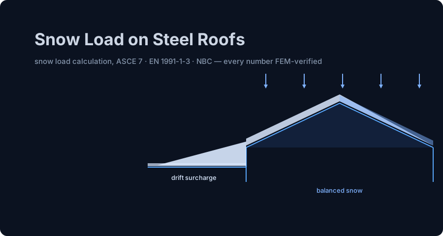
Snow load calculation from ASCE 7 ground snow to a drift-tested steel roof, with FEM-verified numbers and a free load-combination calculator, no login.
Key takeaways
- Flat-roof snow p_f = 0.7·Ce·Ct·Is·p_g turns a 40 psf ground snow into 28 psf (1.34 kN/m²), the balanced load every roof member carries.
- On a determinate purlin the FEM engine reproduced wL²/8 exactly: 2.011 kN/m over 6 m gave M_max = 9.05 kN·m and reactions of 6.03 kN, matched to three decimals.
- On an indeterminate gable frame, balanced snow gave a 287 kN·m ridge moment with zero sway; unbalanced snow leaned the frame (ridge sway 0 → 0.18 cm) and unbalanced the knees, a pattern only FEM reveals.
- A snow drift at a roof step (ASCE 7 §7.7) doubled the beam moment from 16.1 to 32.6 kN·m and pushed the wall reaction from 8.0 to 21.6 kN, which is exactly how drifted snow collapses roofs.
- Design still reduces to one number: utilization = demand / capacity < 1.0, checked automatically against AISC 360, Eurocode 3 or NBR 8800.
Snow Load Calculation: From ASCE 7 to a Steel Roof
It is the middle of winter, and somewhere in snow country a single-storey steel warehouse is carrying a ground snow load of 40 psf (1.92 kN/m²) on the ground around it. That number is not a weather statistic: it is the input that decides how heavy the purlins are, how far the rafters can span, and whether the roof is still standing when a storm dumps a metre of snow and the wind piles half of it into one valley. Getting the snow load calculation right is the difference between a roof that shrugs off a blizzard and one that ends up on the floor.
This guide walks the whole path, end to end: from a mapped ASCE 7 ground snow load in psf, through the factored load combinations, and into a real steel roof analysed with a finite-element engine. Every result below is engine-verified, not hand-waved: we ran three worked examples through the CalcSteel FEM solver and print the exact numbers it returned. Along the way there is a live load-combination calculator you can drive yourself, for free, with no login.
We wrote this for three readers at once:
- The student who needs the physics and the formula to actually make sense (start at how snow loads a roof).
- The practising engineer who wants the code bookkeeping, the governing combinations and the frame behaviour (jump to the gable-frame example).
- The curious reader who just wants to know why roofs cave in under snow (that answer lives in worked example 3, and it hinges on snow that piles up unevenly).
Keep one thing in the back of your mind as you read. Snow almost never governs a roof by lying on it uniformly. It governs by collecting: sliding off a steep face onto a flat one, drifting against a parapet or a taller wall, loading one side of a gable while the wind scours the other. Uniform snow is the easy case. The dangerous cases are the uneven ones, and only a real structural model captures how they redistribute the load.
How snow actually loads a roof
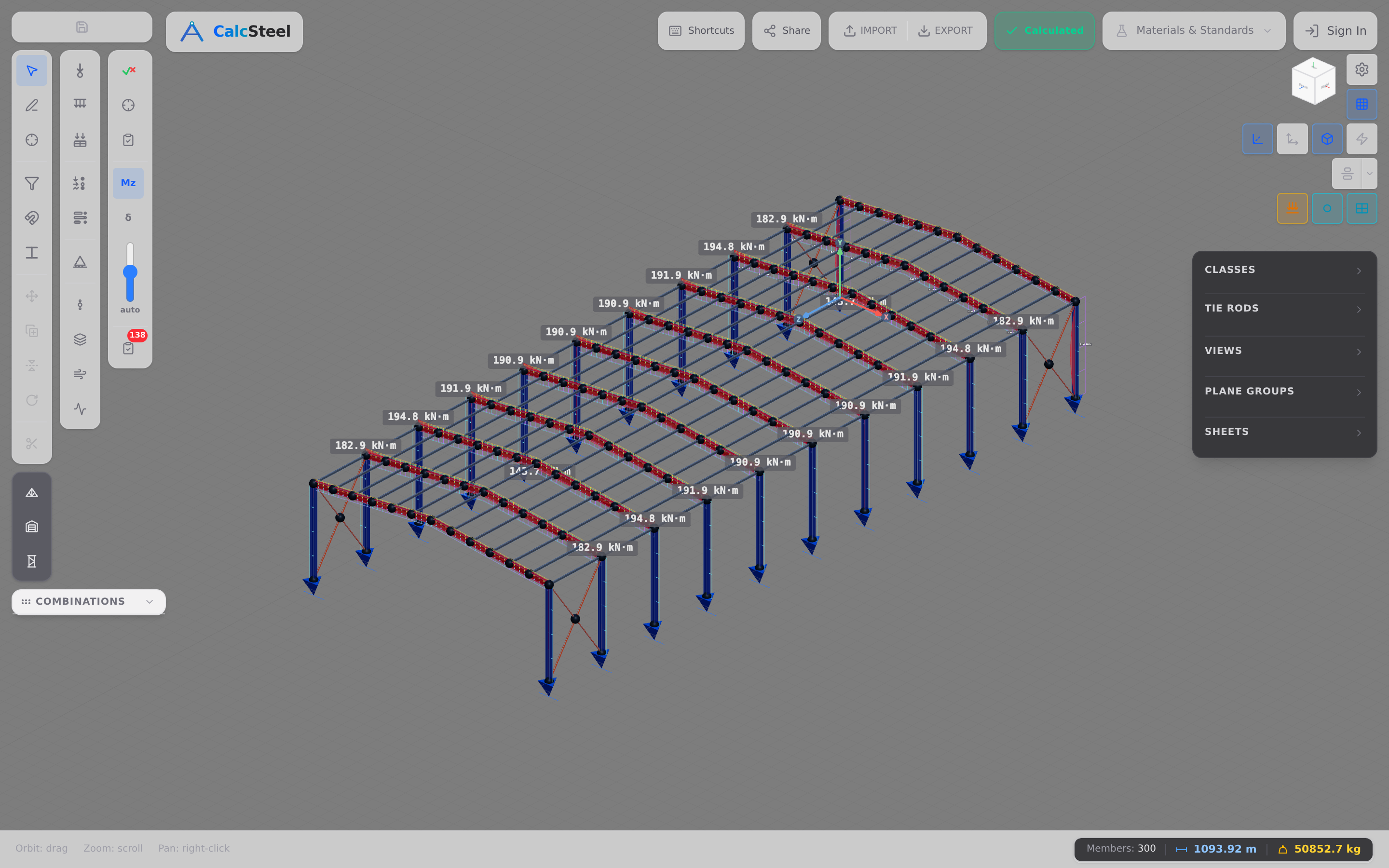
Snow load is the weight of accumulated snow (and any absorbed rain) resting on a roof: a downward area load, measured in kN/m² or psf, that acts vertically on the horizontal projection of the roof. Unlike wind, it never reverses and never lifts; it only pushes down. What makes it tricky is not its direction but its distribution, because snow does not sit still.
The starting point is the ground snow load, the weight of snow that would accumulate on open, flat ground at the site over the design return period. Codes map it directly: ASCE 7 publishes ground snow load pg in psf across the country, with cold, high or mountainous regions carrying the heavy values. Our warehouse sits on a 40 psf (1.92 kN/m²) contour.
A roof does not carry all of that. The roof snow load is generally lighter than the ground snow load, for three physical reasons baked into the code factors:
- Wind scours the roof. Exposed roofs lose snow to the wind that open ground keeps, so the base conversion knocks the ground value down (the 0.7 factor in ASCE 7).
- Heat leaks up through the roof. A heated building melts the underside of the snowpack, so a warm roof carries less than a cold, unheated one (the thermal factor).
- Slope sheds snow. Steep, slippery roofs let snow slide off; the steeper and more slippery, the less stays (the slope factor).
But every one of those mechanisms also moves snow, and moved snow has to land somewhere. That is where the danger lives:
- Balanced snow: the uniform layer left on the roof after the base reductions. This is the easy load, the one everyone remembers to check.
- Unbalanced snow: on a gable or hip roof, wind sweeps the windward slope nearly clear and dumps that snow on the leeward slope, loading one side far more than the other.
- Drift: where a roof steps down, meets a parapet, or sits below a taller neighbour, wind-blown snow piles into a triangular drift that can be two or three times the balanced depth.
That last one, drift, is the counter-intuitive killer, and we quantify it in worked example 3. Balanced snow is what the roof was designed for; drifted snow is what actually collapses it. Hold that thought.
Calculating snow load: flat-roof snow (ASCE 7)
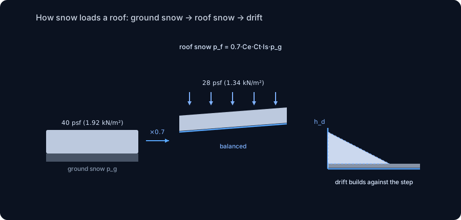
ASCE 7-22, the US standard, turns the mapped ground snow load into a design flat-roof snow load pf with one working formula:
pf = 0.7 · Ce · Ct · Is · pg
The constant 0.7 is the base ground-to-roof conversion (the wind-scour reduction for a typical roof). Everything else is a factor that adjusts it for the real building:
- Ce (exposure factor): how wind-exposed the roof is. A fully wind-swept roof carries less (Ce as low as 0.7); a sheltered roof surrounded by trees or taller buildings carries more (up to 1.2). For our partially exposed warehouse, Ce = 1.0.
- Ct (thermal factor): how warm the roof is. A normally heated building melts snow from below, so Ct = 1.0; an unheated or freezer building keeps it, so Ct rises to 1.1 or 1.2.
- Is (importance factor): tied to the risk category. Ordinary buildings (Risk Category II) use Is = 1.0; hospitals and other essential facilities carry more.
Plugging in Ce = 1.0, Ct = 1.0, Is = 1.0 and pg = 40 psf:
pf = 0.7 × 40 = 28 psf = 1.34 kN/m².
That is the balanced snow load on a low-slope roof. Two adjustments can still change it before it reaches a member:
- Sloped-roof snow ps = Cs · pf: on a steep, slippery roof the slope factor Cs reduces the load because snow slides off. On our shallow 14° warm roof, Cs ≈ 1.0, so ps ≈ pf = 28 psf.
- Minimum snow load pm: for low-slope roofs ASCE 7 sets a floor (for pg > 20 psf, pm = 20·Is = 20 psf) so a wide flat roof is never designed for less than a solid uniform layer. Here 28 psf already governs.
- Rain-on-snow surcharge: on nearly flat roofs (slope below ½ on 12) a 5 psf surcharge is added, because rain soaks into the snowpack and cannot drain, adding weight the snow alone would not.
Every one of these is a hand calculation you can reproduce with a pencil. The moment they enter a real frame, though, and especially the moment the snow stops being uniform, the arithmetic stops being linear, and that is where the FEM engine earns its keep. First, let us see the codes that reach this same load by different routes.
Three codes, one idea: ASCE 7 vs Eurocode vs Canada
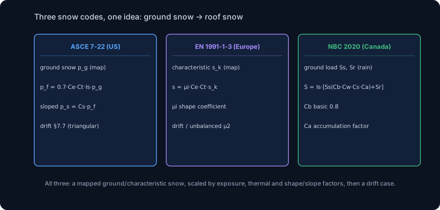
Snow physics is universal, but every cold-climate region books it differently. If you work across markets, it helps to see that ASCE 7, the Eurocode and the Canadian code are the same ground-snow-to-roof-snow idea wearing three sets of clothes. All three start from a mapped ground or characteristic snow, scale it for exposure, temperature and roof shape, then add a drift case. Only the symbols and packaging change.
- ASCE 7-22 (United States): works in psf. You start from the mapped ground snow pg, form the flat-roof snow pf with the 0.7 conversion and the C and I factors, apply the slope factor Cs, and add drift per §7.7. This is the route we worked above.
- EN 1991-1-3 (Eurocode, Europe): starts from a characteristic ground snow sk from national maps and forms the roof snow s = μi · Ce · Ct · sk, where μi is a roof-shape coefficient that already carries the slope and the drift/unbalanced patterns (the μ2 triangular cases). Different symbols, identical logic.
- NBC 2020 (Canada): a country that takes snow very seriously. The specified load is S = Is[Ss(CbCwCsCa) + Sr], where Ss is the ground snow, Sr the associated rain load, Cb a basic roof factor (0.8, the same idea as ASCE's 0.7), and Ca an accumulation factor that plays the role of the ASCE drift and unbalanced cases.
The takeaway is liberating: understand one snow code and you understand all three, because the engineering is one idea (mapped snow, reduced for the roof, redistributed by wind) and the codes are bookkeeping conventions around it. And notice who is not on this list: Brazil. NBR does not have a snow-load standard, because Brazil essentially does not get structural snow, which is why we compare Canada and Europe here instead of NBR 6123's wind. It is a useful reminder that the load cases you must check are set by your climate and your code, not by habit.
What differs in practice is the shape coefficients and, crucially, the load combinations each code pairs with its snow load. The CalcSteel load-combination calculator generates the factored combinations for ASCE 7, EN 1990 and NBR 8681 side by side, with the snow factors broken out, so you can see how the same characteristic snow is amplified differently under each standard. It is free, needs no login, and it is embedded a little further down for you to try.
Worked example 1: a roof purlin under balanced snow
Theory is cheap until it has to hold a roof up in a blizzard. So let us take the snow load we just calculated and put it on a real member: a roof purlin, the beam that spans between frames and carries the roof sheeting. This is the cleanest place to start because a purlin is statically determinate: simply supported at each end, one span, one load. The hand formula and the FEM engine should agree to the last decimal, and they do.
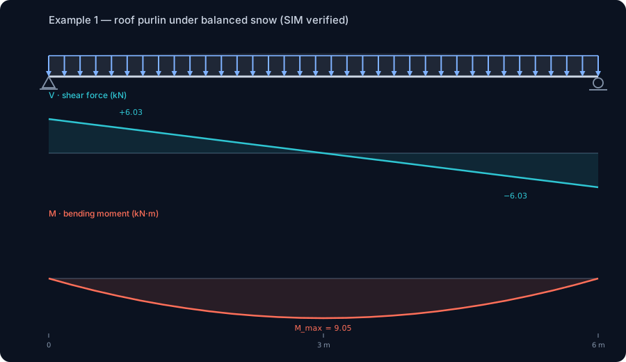
Here is the setup. The roof sees the balanced snow load from the section above: 1.34 kN/m² pressing down (that is the 28 psf flat-roof value). Each purlin supports a strip of roof one purlin-spacing wide. With a purlin spacing of 1.5 m, the area load collapses into a line load along the purlin:
- w = 1.34 kN/m² × 1.5 m = 2.011 kN/m (a uniformly distributed load, acting straight down).
The purlin spans L = 6 m between frames, pinned at both ends. From here the classic simply supported results apply:
- End reactions: R = wL / 2 = 2.011 × 6 / 2 = 6.03 kN at each support.
- Maximum shear: Vmax = 6.03 kN, at the supports (shear is largest where the reactions are, and it crosses zero at midspan).
- Maximum moment: Mmax = wL² / 8 = 2.011 × 6² / 8 = 9.05 kN·m, at midspan.
We ran the identical purlin through the CalcSteel FEM engine, and it returned R = 6.033 kN, Vmax = 6.033 kN and Mmax = 9.05 kN·m, an exact match to three decimals. That is the whole point of a determinate check: when closed-form theory and the solver agree perfectly, you trust the solver on the hard problems where no closed form exists (those are Examples 2 and 3). If you want to see how the shear and moment build up along the span, the walkthrough in shear force and bending moment diagrams takes the same simply supported case apart step by step.
One warning that matters in snow country: this 9.05 kN·m is the balanced load. The very same purlin, if it sits on a lower roof next to a taller wall, can pick up a snow drift that more than doubles this moment, and it does so without any change to the ground snow number. We prove exactly that in worked example 3. For now, size the purlin for 9.05 kN·m and hand it to the beam calculator to confirm the section and the deflection.
Try it: live load-combination calculator
Before we load a whole frame, get your hands on the numbers yourself. The calculator embedded right here builds the factored load combinations for you: it takes your dead, live, snow, wind and other actions and generates the full ULS (strength) and SLS (service) combination sets side by side for NBR 8681, ASCE 7 and EN 1990, with the snow factors broken out so you can see exactly where the 1.6S, the 0.5S and the load factors land.
That side-by-side view is the fastest way to internalise how snow actually enters a design. Type in a dead load and a snow load, then watch how 1.2D + 1.6S (snow as the leading variable action) usually governs the roof members, while snow also shows up reduced as a companion, 0.5S, in the wind combination and as part of the seismic mass. Snow is rarely alone, and the factor it carries depends on whether it is leading or tagging along.
- Free, no login, nothing to install. It runs in your browser like the rest of the CalcSteel calculators.
- It speaks three codebooks at once, so a student learning ASCE 7 and a practising engineer working to NBR 8681 or Eurocode see the same physics in their own notation.
Open the load-combination calculator, run your own D, S and W, then come back: the next two worked examples take these exact combinations and push them through a real steel roof.
NBR 8681
82.6 kN
governing ULS
ASCE 7-16/22
71 kN
governing ULS
EN 1990
84 kN
governing ULS
Code spread
18.3%
EN 1990 governs
Governing ULS by code — parcel makeup
NBR 8681
Ultimate (ULS / ELU)
Serviceability (SLS / ELS)
ASCE 7-16/22
Ultimate (ULS / ELU)
Serviceability (SLS / ELS)
EN 1990
Ultimate (ULS / ELU)
Serviceability (SLS / ELS)
24 combinations across 3 codes · math in SI, display in kN
Load combinations: where snow gets heavy
Snow never shows up by itself. A roof is always carrying its own weight and its dead loads, and the snow arrives on top of that, sometimes with wind pushing it sideways or rain soaking into it. Load combinations are the rulebook that says how much of each action to apply at once, and for snow the important discovery is that the governing case is often not the uniform one.
Start with the combinations that put snow front and centre. In ASCE 7 (LRFD):
- 1.2D + 1.6S: snow as the leading variable action, at its full 1.6 factor. This is the combination that sizes most roof members, purlins, rafters and the frame under gravity.
- 1.2D + 1.6S + (0.5W or 0.5L): full snow with a companion wind or roof live load.
- 1.2D + 1.0W + 0.5S: wind leads, snow tags along at the reduced 0.5 factor.
- 1.2D + 1.0E + 0.2S: in the seismic combination, a fraction of the snow (0.2S) is even carried as part of the mass that the earthquake accelerates.
Every major code encodes the same idea with different bookkeeping, and the embedded load-combination calculator lays them out together: Eurocode (EN 1990) treats snow as a variable action with a combination factor ψ0 = 0.5 (0.7 at high altitude) when it accompanies another leading action; NBR 8681 (Brazil) uses its γ and ψ0 factors the same way, on the rare projects where snow is even considered.
But here is the twist that the combination table alone will not tell you. The 1.6 factor answers how much snow, and the real trap is where the snow is. A load pattern, not just a load magnitude, decides the design:
- Balanced snow loads the whole roof evenly, and 1.2D + 1.6S balanced sizes the ordinary members.
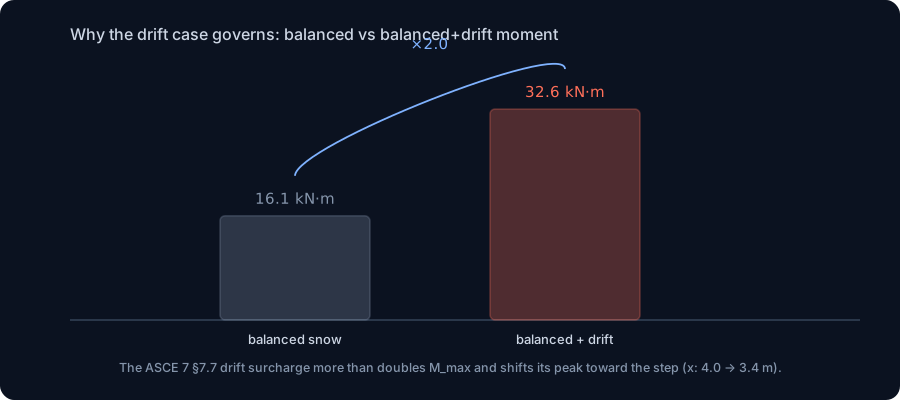
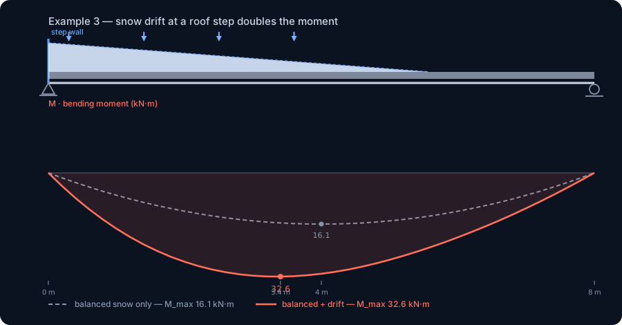
- Drifted snow concentrates the same 1.6S into a triangular pile at a step or wall, and it can more than double the local demand, as the chart below previews and Example 3 proves with the FEM engine.
The takeaway before we run the numbers: you must check the roof under uniform snow and under drifted snow, both at the 1.6 factor. For most members the balanced case wins. For a beam under a drift, the drifted case is the killer, and no amount of load-factor bookkeeping will save a member that was only ever checked for the uniform layer.
Worked example 2: the frame leans (gable frame + unbalanced snow)
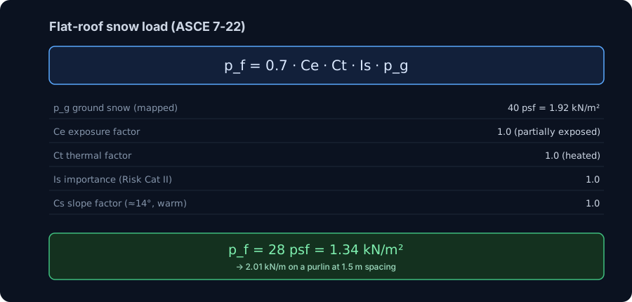
The purlin in Example 1 was determinate: one span, two supports, a formula. A real building is not. Take a single-storey gable-frame warehouse: a 20 m span, 6 m eave columns, a ridge 2.5 m above the eaves (a shallow 14°, roughly 3:12 pitch), fixed bases, a 6 m bay, W610x125 rafters and columns. Load the whole roof with snow and it settles symmetrically. Load only one side and the whole frame leans. There is no closed-form answer for the moments, because the structure is statically indeterminate: the loads redistribute according to relative stiffness, and only a finite-element solve tells you where they land.
We ran two snow cases on the same frame in the CalcSteel engine.
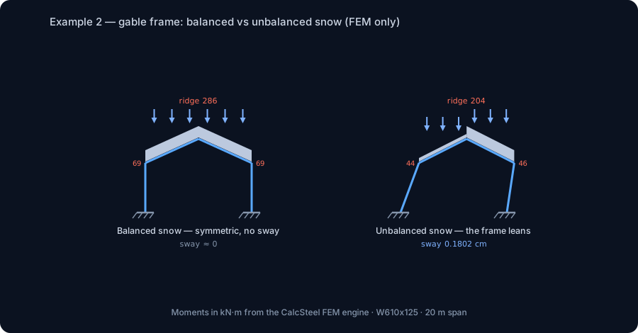
Case A, balanced snow. The full ps = 1.34 kN/m² on both slopes, which over a 6 m bay and projected onto the 14° rafters is a line load of 7.80 kN/m along each rafter (a total of 160.9 kN of snow on the plan area). Because the frame is symmetric, the answer is symmetric too:
- Rafter peak moment near the ridge: 287 kN·m.
- Knee (eave) moment: 68.8 kN·m, equal on both sides.
- Column base moment: 44.5 kN·m, equal on both sides.
- Eave sidesway: 0. The eaves push apart symmetrically by 1.54 cm each, but the ridge stays dead-centre. A symmetric frame under symmetric load does not lean.
Case B, unbalanced snow. Now the ASCE 7 unbalanced case: wind has swept the windward slope down to 0.3 ps (a 2.34 kN/m line load) and left the leeward slope at the full 7.80 kN/m. The total snow is actually less (104.6 kN), but watch what the asymmetry does:
- Leeward-rafter peak moment: 203.5 kN·m, now higher than the lightly loaded windward rafter's 186.0 kN·m, and the peak has moved out onto the leeward slope.
- Knee moments split apart: 43.9 kN·m on one side, 45.5 kN·m on the other. The base moments unbalance the same way (29.7 vs 28.1 kN·m).
- Eave sidesway: the ridge now drifts 0.18 cm sideways and the two eaves move unequally (-1.18 cm vs +0.82 cm). The frame leans.
Here is the insight hand calc will never hand you. Balanced snow, the heavier case, governs the rafters and the ridge: 287 kN·m is the number that sizes the roof beams. But it is perfectly symmetric, so it hides an entire failure mode. Unbalanced snow, even though it is lighter overall, is the only case that makes the frame lean and unbalance its columns left-to-right. If you had checked balanced snow alone, or modelled the frame as symmetric and stopped there, you would have missed the sway and the uneven column demand completely. You must run both cases: balanced snow to size the rafters, unbalanced snow to size the sway and the individual columns. The lateral stiffness that keeps that lean small comes from the fixed bases here; in taller or wider frames it comes from bracing (see bracing systems for steel and columns, beams and bracing).
The base reactions confirm the physics closes: the fixed feet carry exactly the 160.9 kN of balanced snow (and 104.6 kN unbalanced) with nothing leaking. You can build this exact frame in the CalcSteel editor, apply both snow patterns, and read the moment diagram and the sway straight off the model.
Worked example 3: drift doubles the load (why roofs collapse)
This is the one that caves roofs in. Back on determinate ground, take a lower-roof purlin spanning 8 m, next to a taller wall, a rooftop unit or a stepped-up section of the building. Under balanced snow it carries the same clean uniform line load as Example 1, scaled to its span. But wind blowing over the taller roof scours snow off it and drops it into the sheltered corner against the step, building a triangular drift right where this purlin lives.
ASCE 7 §7.7 gives the drift geometry directly. With a ground snow pg = 40 psf and a long upwind fetch of the upper roof (lu = 150 ft), the formulas return a snow density γ = 0.13·pg + 14 = 19.2 pcf, a drift height hd = 0.43·lu1/3(pg+10)1/4 − 1.5 = 4.58 ft (1.4 m), and a drift width wd = 4·hd = 18.3 ft (5.58 m). The peak surcharge at the wall is pd = hd·γ = 87.9 psf = 4.21 kN/m², more than three times the balanced load, tapering linearly to zero 5.58 m away.
Balanced-only case. The uniform snow line load is w = 2.011 kN/m (as in Example 1). On the 8 m span:
- Midspan moment: 16.1 kN·m, at the centre (= wL²/8).
- Reactions: 8.04 kN at each end, sharing the load evenly.
Balanced + drift case. Now add the triangular drift, a line load peaking at 6.31 kN/m against the wall (that is the 4.21 kN/m² surcharge over the 1.5 m tributary) and tapering to zero at 5.58 m. We fed the exact triangular load into the CalcSteel FEM engine:
- Maximum moment: 32.6 kN·m, at x = 3.4 m from the wall. The moment has doubled, and its peak has shifted from midspan toward the drift.
- Reactions: 21.6 kN at the wall end against just 12.1 kN at the far end. The support next to the drift now carries nearly twice what balanced snow put on it.
We hand-checked the same case by superposition of the uniform and triangular loads, and it lands on 32.6 kN·m and 21.6 kN to three significant figures, exactly what the engine returned. Read what physically changed. The ground snow number never moved: it is still a 40 psf site. But a member sized for the balanced 16.1 kN·m is carrying 32.6 kN·m, so it is loaded to twice its design moment at a spot the uniform check never flagged. That is not a rounding error. That is a collapse.
This is why snow drift is the single most common cause of snow-related roof failures: not record snowfalls on the whole roof, but ordinary snow that the wind rearranges into a pile the designer did not account for. The uniform check looks fine; the roof comes down at the step. Gravity-only, uniform-only design never reveals it, which is exactly why ASCE 7 forces the §7.7 drift case on you. You can reproduce the balanced case in seconds on the free beam calculator, and generate the factored combinations that wrap around it with the load-combination calculator.
Where snow collapses roofs: steps, valleys and the load path
Example 3 ended with a number that should worry you: a purlin loaded to twice its design moment by a drift the uniform snow check never saw. Snow failures rarely happen in the middle of a clean, open roof. They happen at the discontinuities, the places where wind can pile snow deeper than the balanced layer. Learn to spot them and you have found most of the risk.
The classic drift and accumulation locations, all of which ASCE 7 Chapter 7 makes you check explicitly:
- Roof steps. A lower roof next to a taller wall, exactly our Example 3. Wind sweeps the high roof and drops the snow against the step. The longer the upper roof (the fetch), the bigger the drift.
- Parapets. Even a single roof grows a drift behind its own parapet wall, because the parapet does the same job as a taller neighbour.
- Rooftop units and obstructions. Mechanical units, screens and penthouses each cast a drift shadow that loads the roof around them.
- Valleys and unbalanced gables. On a gable or a valley between two roofs, snow slides and drifts to the low line, the unbalanced case from Example 2.
- Sliding snow. Snow shedding off a steep upper roof lands as an extra load on the lower roof below, on top of whatever is already there.
Two more effects stack on top of drift and deserve a line each. Rain-on-snow adds weight when rain soaks a snowpack that cannot drain, most dangerous on low slopes. And ponding is the vicious-circle failure: a flat roof deflects under snow, the low spot collects meltwater, the extra water deflects it further, and if the roof is too flexible the cycle runs away. All three are load-path problems: the snow, the drift, the water, and finally the reactions all have to travel from the sheeting through the purlins and rafters into the columns and the foundation, and the weakest link governs.
There is a nasty real-world corollary. Drift loads change when the neighbourhood changes. A roof that was fine for twenty years can become under-designed the day a taller building goes up next door, or a new rooftop unit is installed, because the drift it now has to carry did not exist when it was designed. Any time the geometry around a roof changes, the drift case has to be rechecked.
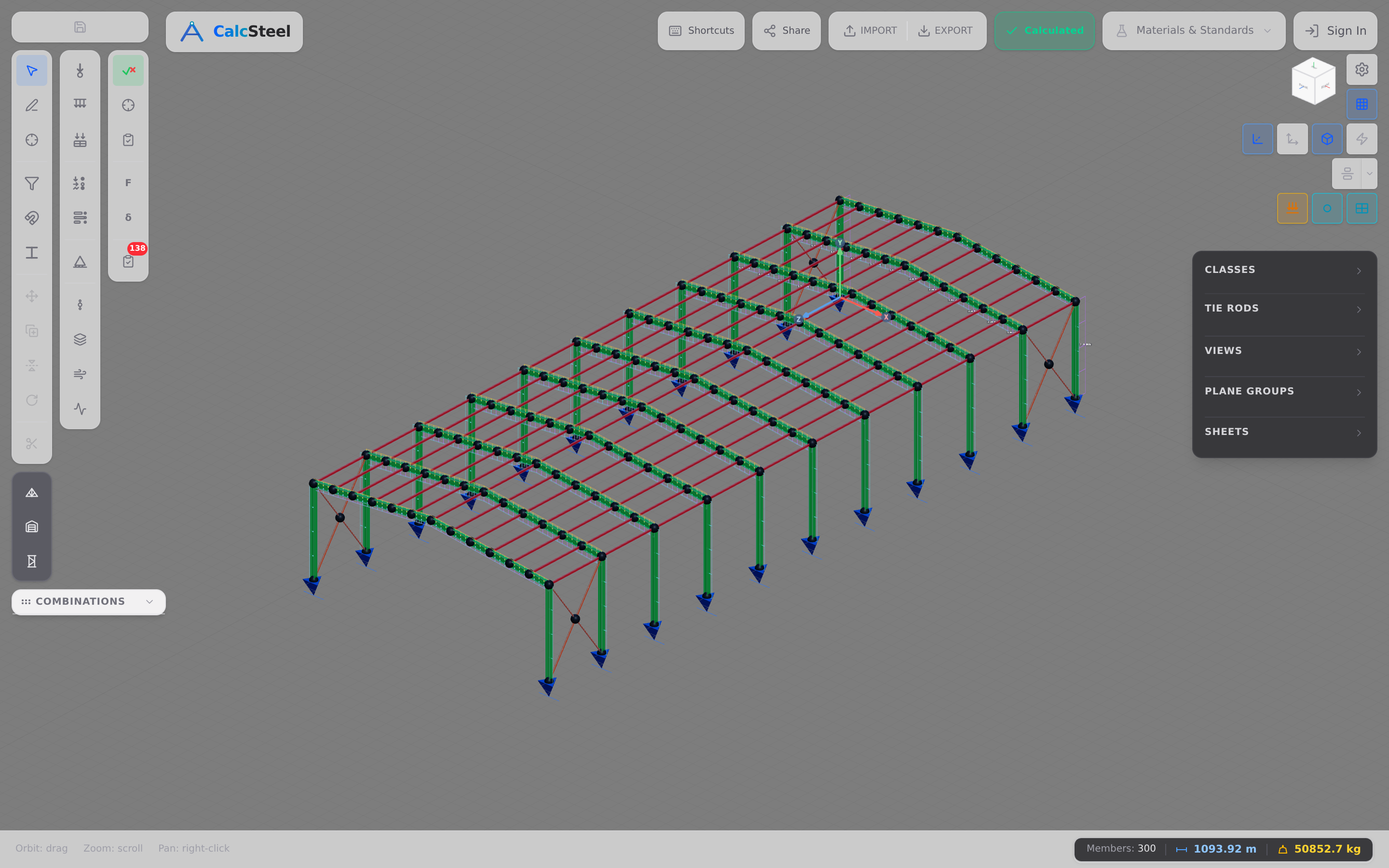
When you run the snow combinations on a real model in CalcSteel, the verification colours make the weakest link obvious: the members that the balanced and drifted snow cases push toward or past their capacity light up, so you fix the actual governing element instead of guessing. On a snow-country roof, the red is far more often at a drifted step or an overloaded valley purlin than in the middle of a clean span.
From snow load to a sized member
A load is not a design. The path from a snow number to a steel section is short but strict: pick the governing combination and pattern, read the peak demand off the FEM run, then check that demand against the member's capacity. If utilization = demand / capacity < 1.0, the member passes. If not, you go up a size, change the section, or add support. That single ratio is what every snow calculation is really chasing.
Each part of the roof is governed by a different case, and the three worked examples above already showed which one:
- The ordinary purlin or rafter is sized for 1.2D + 1.6S balanced. In Example 1 the 1.34 kN/m² balanced snow over a 1.5 m tributary gave Mmax = 9.05 kN·m on a 6 m span; that moment, at the full 1.6 factor, sets the ordinary member.
- The frame is governed by balanced snow for the rafters and ridge (the 287 kN·m of Example 2) but by unbalanced snow for the columns and the sway, because only the asymmetric case leans the frame and unbalances the feet. Both cases, one frame.
- The beam under a drift is governed by 1.2D + 1.6S with the §7.7 drift pattern. In Example 3 that pattern took the moment from 16.1 to 32.6 kN·m; a member sized for the balanced case alone is loaded to twice its design value.
In the CalcSteel FEM engine this is not three separate hand checks. You define the snow cases once, the solver builds the ULS and SLS combinations, and every member is classified and verified automatically against your chosen code: AISC 360, Eurocode 3 (EN 1993) or NBR 8800. The engine handles section classification, the flexural and axial resistances and the interaction equations, then colours each member by its governing utilization so you see at a glance which element the snow pushes hardest. The numbers behind that picture are the same 9.05 kN·m, 287 kN·m and 32.6 kN·m you just followed by hand: nothing is hidden, everything is checkable.
Two serviceability checks ride along with the strength check and matter just as much for snow. Deflection: a roof that sags too far under snow can pond water and fail the way the previous section described, so the snow deflection is capped (see deflection and drift limits). And the load path into the foundation: the reactions from a drifted beam, 21.6 kN at one end in Example 3, have to be carried by the connection and the support below, not just the beam itself.
The takeaway for sizing: do not size a member for one snow case and assume it covers the rest. The purlin wants full balanced snow, the columns want the unbalanced pattern, and the beam at a step wants the drift. Miss one and you have sized the wrong thing for the wrong case.
Common mistakes & FAQ
Snow is where careful engineers still get caught, because the dangerous case is rarely the uniform one. Here is the checklist we run through before trusting any snow design.
- Designing for ground snow instead of roof snow. The ground value pg is the input, not the load. Forgetting the 0.7 conversion (and the C and I factors) over-designs the roof; using it where it does not apply, such as a sheltered or unheated roof that should carry more, under-designs it.
- Skipping the drift case. This is the big one, the single most common cause of snow collapses. A roof checked only for balanced snow is unchecked at every step, parapet and rooftop unit, and Example 3 showed drift doubling the demand there.
- Forgetting unbalanced snow on gables and valleys. The lighter, asymmetric case leans the frame and unbalances the columns, as Example 2 proved. A symmetric balanced-only analysis never sees it.
- Ignoring the minimum snow load. On a low-slope roof, ASCE 7 sets a floor (pm) that a wide flat roof can never be designed below, regardless of how the slope and exposure factors work out.
- Missing rain-on-snow and ponding. On nearly flat roofs, rain soaking into the snow adds weight the snow alone would not, and a flexible roof that sags can pond meltwater into a runaway failure.
- Not rechecking drift when the surroundings change. A new taller neighbour or a new rooftop unit creates a drift that did not exist when the roof was designed. The snow map did not change, but the load did.
How do you calculate snow load on a roof?
Start with the mapped ground snow load pg for your site. In ASCE 7-22, convert it to the flat-roof snow load with pf = 0.7·Ce·Ct·Is·pg; for our 40 psf site with all factors 1.0 that gave pf = 28 psf = 1.34 kN/m². Apply the slope factor for a sloped roof (ps = Cs·pf), check the minimum snow load, add the drift surcharge per §7.7 wherever the roof steps or meets a wall, then turn the area loads into line loads on your members and run the combinations. The free load-combination calculator handles the combination bookkeeping.
What is the difference between ground snow and roof snow?
Ground snow is what accumulates on open, flat ground at your site, the mapped value the code gives you. Roof snow is what actually rests on the roof, and it is usually lighter, because wind scours the roof, building heat melts the underside, and slope sheds it. The 0.7 factor and the C and I factors in ASCE 7 do that conversion. The exception is drift, where wind piles roof snow far deeper than the balanced value in local spots.
Why do roofs collapse under snow?
Almost always because of drift, not uniform depth. Wind rearranges ordinary snow into a triangular pile against a step, parapet or taller wall, and in Example 3 that drift doubled the beam moment, from 16.1 to 32.6 kN·m, at a spot the uniform snow check never flagged. The roof looks fine on paper for balanced snow and fails at the drift. That is why ASCE 7 §7.7 forces the drift case.
Does Brazil need snow load design?
Essentially no. Brazil does not get structural snow, and NBR has no snow-load standard, which is why the wind load (NBR 6123) dominates Brazilian roof design instead. Snow governs in North America, Europe, the higher latitudes and the mountains; your climate and your code decide whether it is a load case at all. If you build in a cold climate, use ASCE 7, the Eurocode or the national code that applies.
ASCE 7 vs Eurocode snow, are they really different?
Same physics, different bookkeeping. Both start from a mapped ground or characteristic snow, reduce it for the roof (ASCE's 0.7 conversion, the Eurocode's shape coefficient μi), adjust for exposure and temperature, and add drift and unbalanced cases. The loads land in the same ballpark; the symbols and the shape coefficients differ. The CalcSteel combination tool covers ASCE 7, EN 1990 and NBR 8681 side by side so you can compare the factored results directly.
Key takeaways
Snow load calculation is a straight line from a number on a map to a sized steel member, and every step is checkable. Here is what to carry away.
- It starts with a conversion, not a copy. pf = 0.7·Ce·Ct·Is·pg turned a 40 psf ground snow into a 28 psf (1.34 kN/m²) balanced roof load. The ground value is the input; the roof value is the load.
- The determinate check gives you trust. A 2.011 kN/m purlin over 6 m gave Mmax = 9.05 kN·m and 6.03 kN reactions, and the FEM engine reproduced wL²/8 to three decimals, so you can believe it on the hard cases.
- Snow rarely governs the beam by lying flat. On the gable frame, balanced snow sized the rafters at 287 kN·m, but only the lighter unbalanced case leaned the frame (ridge sway 0 → 0.18 cm) and unbalanced the columns. Run both.
- Drift is the killer. The ASCE 7 §7.7 drift at a roof step doubled the beam moment from 16.1 to 32.6 kN·m and pushed the wall reaction to 21.6 kN, all without changing the ground snow number. That is how drifted snow collapses roofs, and it is why the drift case is mandatory.
- Design is one number: utilization < 1.0. Demand from the governing combination and pattern over code capacity (AISC 360, Eurocode 3 or NBR 8800), computed automatically once the model and the snow cases are in.
Want to see it for yourself? The load-combination calculator builds your ULS and SLS combinations for ASCE 7, EN 1990 and NBR 8681 with the snow factors broken out, free and with no login. From there, drop the same roof into the full CalcSteel editor and let the FEM engine run the balanced, unbalanced and drift cases end to end.
CalcSteel is a genuinely free, browser-native structural steel design and analysis solution: a real FEM engine plus a suite of free calculators, no trial clock and no credit card. Students get it free through CalcSteel for Education. Model the roof, apply the snow, and watch which members the drift lights up. The best way to trust these numbers is to reproduce them.
Sources
- 1.ASCE/SEI 7-22: Minimum Design Loads and Associated Criteria for Buildings and Other Structures (Ch. 7, Snow Loads)
- 2.EN 1991-1-3:2003: Eurocode 1, Actions on structures, Part 1-3: Snow loads
- 3.National Building Code of Canada 2020: Snow and Rain Loads (Div. B, 4.1.6)
- 4.O'Rourke, M.: Snow Loads, Guide to the Snow Load Provisions of ASCE 7 (ASCE Press)
Try CalcSteel for free
Model, analyze and design steel structures in your browser. No install, no signup.
Open the 3D editor