Shear Studs and Partial Composite Action: How Many Studs Before the Slab Stops Helping

Make a steel beam composite with the slab it already carries and its design moment can nearly double, but only if the shear studs can drag the two materials along together. The studs are the whole mechanism, and the honest question is how many you actually need. This guide takes one real beam, an IPE 400 on a 10 m span with a 500 kN·m factored moment from a CalcSteel run, and walks it from bare steel (384 kN·m) through partial composite action to full composite (745 kN·m with 60 studs) to AISC 360 Chapter I. The surprise is how quickly the curve flattens: the first studs buy most of the strength, and past full composite the slab simply stops helping, no matter how many more you weld on.
Key takeaways
- Studs are the mechanism, not an accessory. Without them the slab and the beam slide past each other and each bends alone; the studs transfer the horizontal shear that makes them act as one deeper section. Bare steel here gives 384 kN·m, full composite gives 745 kN·m.
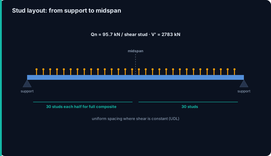
- Full composite action needs the studs to carry V' = min(As Fy, 0.85 f'c Ac). Here that is min(2783 kN, 5525 kN) = 2783 kN, the steel yield force, and at 95.7 kN per 19 mm stud it takes 30 studs each side of midspan, 60 on the beam.
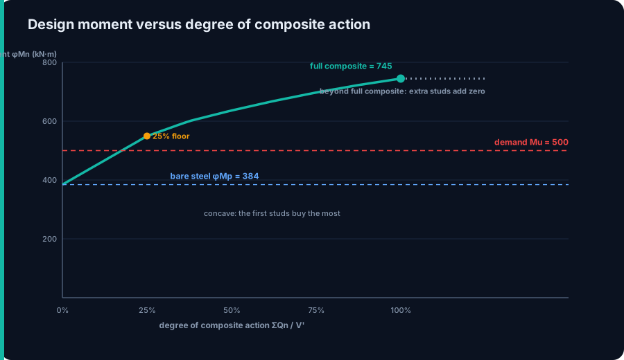
- The moment-versus-studs curve is concave. The first 50 percent of composite action adds 252 kN·m; the last 25 percent adds only 47. So partial composite action is usually the buy: you reach for full composite for stiffness, not for the last scrap of strength.
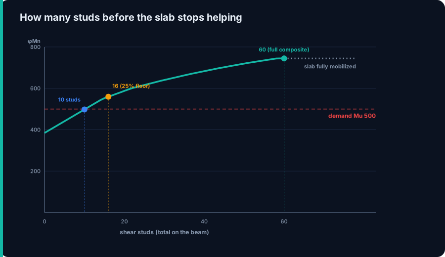
- Past full composite the slab stops helping, exactly. Once the studs can transfer V', the concrete is fully mobilized and every additional stud adds zero flexural capacity. The 61st stud on this beam changes nothing.
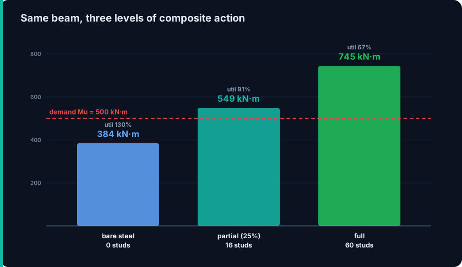
- This beam needs 500 kN·m. Strength alone is met at 16 percent composite (10 studs), the 25 percent practical floor sets 16 studs, and full composite (60 studs) leaves it 33 percent under-utilized. Detailing for full composite would be paying for 44 studs the strength never uses.
Why the slab helps at all
Pour a concrete slab on top of a steel beam and, left to themselves, the two just rest on each other. Under load they both sag, but the slab slides along the top of the beam: the bottom of the slab stretches, the top of the beam shortens, and the interface slips. Each piece carries its own moment on its own neutral axis, and the pair is only as strong as the sum of two shallow sections.
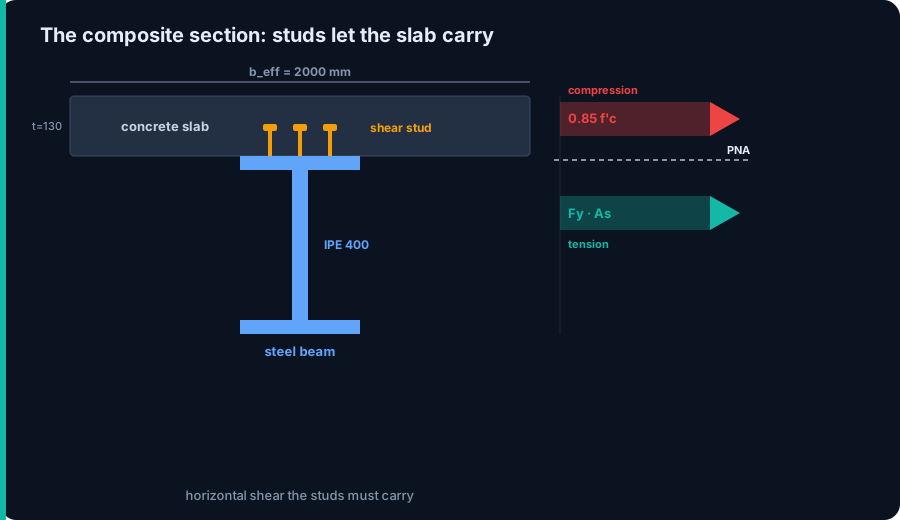
Shear studs stop the slip. Weld enough headed studs to the top flange and the horizontal shear that wants to slide the slab is instead carried across the interface, forcing the slab and the beam to bend about one common neutral axis. Now the concrete works in compression where it is strong, the steel works in tension where it is strong, and the lever arm between them is the depth of the whole assembly, not of the bare beam. That is composite action, and the studs are the entire mechanism behind it.
The worked beam: where the 500 kN·m comes from
The demand is not assumed. A simply supported beam of 10 m span carries a factored uniform load of 40 kN/m, and the CalcSteel engine returns a midspan moment of 500 kN·m, exactly the closed-form wL²/8. That is the moment the composite section has to develop, so Mu = 500 kN·m is the number to beat.
The steel is an IPE 400 in grade 345 steel (Fy = 345 MPa), taken as three plates for the plastic analysis: area As = 80.7 cm², plastic modulus Zx = 1238 cm³. The slab is 130 mm thick in 25 MPa concrete, and the effective width for this interior beam works out to beff = 2000 mm. Bare, this beam has a design moment φMp = 0.9 Fy Zx = 384 kN·m, which is less than the 500 it has to carry. On its own the steel fails; it needs the slab.
Full composite action: the horizontal shear the studs must carry
For the slab and the beam to reach their full combined strength, the studs between the point of maximum moment and the nearest point of zero moment have to transfer the smaller of two forces: the steel yielding in tension, or the concrete crushing in compression. In AISC 360 that is V' = min(As Fy, 0.85 f'c Ac). Here As Fy = 2783 kN and 0.85 f'c Ac = 5525 kN, so V' = 2783 kN and the steel governs: the whole beam can yield before the slab is anywhere near crushing.
With the steel force smaller, the plastic neutral axis sits up in the slab. The concrete stress block is a = AsFy / (0.85 f'c beff) = 65.5 mm deep, and the lever arm from the steel centroid to the middle of that block is h/2 + t − a/2 = 297 mm. The full composite design moment is φMn = 0.9 × 2783 kN × 0.297 m = 745 kN·m, almost double the bare steel. That is the prize the studs unlock, and the rest of this article is about how much of it you actually have to buy.
Counting the studs for full composite action
One stud does not carry much. A 19 mm (3/4 in) headed stud has two strength limits in AISC 360 Section I8: the concrete it bears against, Qn = 0.5 Asc √(f'c Ec) = 110 kN, and the stud steel itself, Rg Rp Asc Fu = 96 kN with Rg = 1.0, Rp = 0.75 and Fu = 450 MPa. The smaller governs, so Qn = 95.7 kN per stud.
To transfer the full V' = 2783 kN you need V'/Qn = 2783 / 95.7 = 29.1, rounded up to 30 studs between midspan and each support, and 60 studs on the beam. Because the shear on a uniformly loaded beam is constant in the sense that matters here, the studs are simply spread at a uniform spacing over each half. Sixty studs is the price of full composite action, and it is worth asking, before you specify it, whether this beam needs anywhere near that many.
Partial composite action: the curve that flattens
You do not have to provide the full 60 studs. Give the beam fewer, and the studs can only transfer ΣQn < V'. The concrete force is now limited to what the studs deliver, the plastic neutral axis drops down into the steel, and the design moment lands somewhere between bare steel and full composite. This is partial composite action, and the degree of it is ΣQn / V'.
The key fact is the shape of the curve, and it is concave. Going from 0 to 50 percent composite action lifts the design moment from 384 to 636 kN·m, a gain of 252 kN·m. Going from 75 to 100 percent lifts it from 697 to 745, a gain of only 47 kN·m for the same extra 15 studs. Each stud you add is worth less than the one before, because as the neutral axis moves the lever arm stops growing. The first half of the studs does most of the work; the second half is buying diminishing returns.
When the slab stops helping
There is a hard ceiling, and it answers the title. Once ΣQn reaches V', the concrete is fully mobilized: the slab is already carrying the entire steel yield force, and there is nothing left for another stud to transfer. Add a 61st stud to this beam and the design moment stays at 745 kN·m. Beyond full composite action, extra studs add exactly zero flexural capacity. The slab has stopped helping, and no amount of extra welding changes it.
So the answer comes in two parts. The hard answer is 60 studs: past that, on this beam, the slab is done. The economic answer is much lower, because the curve flattens long before the ceiling. If your beam only has to reach a moment partway up the curve, the studs that would take it from there to full composite are pure cost with no strength to show for it. The engineering skill is reading where your demand crosses the curve, not defaulting to full.
Where this beam actually lands
Our beam has to develop 500 kN·m. Read that across the curve: the composite section reaches 500 at about 16 percent composite action, which is 5 studs each half, 10 studs on the whole beam. Strength alone is satisfied with ten studs, a util of 99 percent. That is the raw number, and it is startlingly small next to the 60 for full composite.
Two things pull the final count up a little. AISC and common practice set a practical floor near 25 percent composite action, below which the joint is too flexible for the partial-composite assumptions to hold, and that floor here means 16 studs (design moment 549 kN·m, util 91 percent). Even so, 16 studs is a long way from 60. Detailing this beam for full composite would weld on 44 studs the strength never uses, and leave the section 33 percent under-utilized. Partial composite action is not a compromise here; it is the correct design.
Deflection still counts, and it pulls the other way
Strength is only half the design. Composite beams are shallow for their span, so they are often governed by deflection, and here composite action earns its keep for a different reason: stiffness. The transformed moment of inertia of the full composite section is about 713 × 106 mm4 against 219 × 106 for the bare steel, so the full composite beam is roughly 3.3 times stiffer. That is a bigger multiplier than the strength gain.
Partial composite action does not give you all of that. Because the interface slips a little, AISC computes an effective (lower-bound) moment of inertia that grows with the square root of the degree of composite action: Ieff = Is + √(ΣQn/V') (Itr − Is). At the partial design above it is about 424 × 106 mm4, well over the bare steel but short of the full value. This is the tension in the whole problem: strength says stop early, deflection says keep going. The right number of studs is whichever limit governs, so check both before you settle on a count.
Detailing that makes the count real
A stud count only means something if the studs can be placed. AISC 360 Section I8 sets the rules: a minimum longitudinal spacing of six stud diameters (about 114 mm for 19 mm studs), a maximum spacing of eight times the slab thickness or 900 mm, at least 25 mm of lateral concrete cover, and a stud length of at least four diameters after welding. On a plain slab the studs go in a single line or in pairs; on steel deck the rib geometry sets how many fit per rib and brings in the Rg and Rp reduction factors that lowered Qn above.
The count also has to physically fit in the shear span. Sixty studs over a 5 m half at 114 mm minimum spacing is comfortable; the same 60 on a short, heavily loaded beam might not fit at all, which is another reason full composite is not always available even when you would pay for it. And the studs must be spread to match the shear diagram: uniform where the shear is uniform, but bunched toward the supports where a point load makes the horizontal shear peak. Place them by the diagram, not by eye.
Try it yourself
The whole chain starts with the moment the beam has to carry, and that is what sets how far up the composite curve you need to climb. Change the span or the load and Mu moves, the required degree of composite action moves with it, and so does the stud count. Use the beam calculator below to run your own simply supported or continuous beam, read the factored moment it returns, and then map that onto the curve above: bare steel first, then the studs that carry you from there to your demand, and only as far as the demand actually reaches.
Max moment
45 kN·m
Max shear
30 kN
Max deflection
10.55 mm
= L/569
Bending stress σ
84.4 MPa
σ = M/Sx
Utilization
44.0%
NBR 8800 · δ ≤ L/250
Geometry & supports
Section
Ix 7999 cm⁴ · Sx 533 cm³ · 42.2 kg/m
Point loads (↓ positive)
None — add as many as you need.
Distributed loads (uniform or trapezoidal)
Model sketch
Diagrams — free PNG / SVG / CSV export, no watermark
Step-by-step — the calculation memory of YOUR beam
IPE 300 · L = 6 m · fy = 250 MPa
1. Reactions (equilibrium of the solved FEM model)
ΣFy = 0 · ΣM = 0
R_A = 30 kN · R_B = 30 kN
2. Peak shear (read from the SFD)
Vmax = |V(x)|max
Vmax = -30 kN @ x = 6 m
3. Peak moment (read from the BMD)
Mmax = |M(x)|max
Mmax = 45 kN·m @ x = 3 m
4. Peak deflection
EI = 15998 kN·m² (E = 200 GPa)
δmax = 10.55 mm @ x = 3 m = L/569
5. Elastic bending stress
σ = Mmax / Sx = 45.00 × 10³ / 533.3
σ = 84.4 MPa
6. Bending check — both codes, side by side
NBR 8800: σ ≤ fy/1.10 = 227.3 MPa · AISC 360: σ ≤ 0.90·fy = 225 MPa
NBR 37.1% PASS · AISC 37.5% PASS
7. Deflection check (serviceability — code-independent)
δ ≤ L/250 = 24 mm
10.55 mm / 24 mm = 44.0% PASS
Recomputed live from the current inputs by the direct-stiffness FEM engine — change any load and every step updates. Reproduce it by hand with the formulas in the sections below.
Lightest catalog profiles that pass (974 flexural candidates · NBR 8800)
| Profile | Std | Weight | Total steel | σ util | δ util | |
|---|---|---|---|---|---|---|
| W310x21 | AISC | 21 kg/m | 126 kg | 83% | 98% | |
| VS 300x23 | BR | 22.6 kg/m | 136 kg | 71% | 84% | |
| U 300x90x6.3 | BR | 23.1 kg/m | 139 kg | 82% | 98% | |
| U 300x100x6.3 | BR | 24.1 kg/m | 145 kg | 77% | 91% | |
| VS 250x25 | BR | 24.6 kg/m | 148 kg | 70% | 100% |
Elastic bending (σ = M/Sx vs fy/γa1, γa1 = 1.10 — NBR 8800) + deflection screening of the full flexural catalog. Lateral-torsional buckling, shear and local buckling are NOT checked here — run the full NBR 8800 / AISC 360 verification in the 3D editor.
AISC, Eurocode and NBR: the same mechanism, other symbols
The worked example is AISC 360, but composite action is code-independent. Eurocode 4 (EN 1994-1-1) builds the same plastic section, calls the studs shear connectors, and writes the stud resistance as the smaller of PRd = 0.8 fu (πd²/4) / γV and a concrete term 0.29 α d² √(fck Ecm) / γV, the exact same two limits with a partial factor instead of φ. It also sets a minimum degree of shear connection that depends on span, playing the role of the 25 percent floor.
ABNT NBR 8800 follows the AISC LRFD format closely, with resistance factors on the connector and on the composite section, and the same ΣQn bookkeeping for partial interaction. Across all three the story is identical: the studs transfer a horizontal shear, the design moment climbs with a concave curve, and it saturates when the connectors can carry the full V'. What moves between codes is the exact connector formula and the minimum-interaction limit, not the mechanism.
Five ways this goes wrong
- Specifying full composite by default. On this beam full composite is 60 studs for a section that only needs 16. The studs are cheap individually and expensive by the hundred; read the curve before you fill the flange.
- Thinking more studs always help. Past V' the design moment is flat. Studs added beyond full composite carry no shear and add no strength; they are welding for nothing.
- Designing for strength and forgetting deflection. The strength-optimal count can be far too flexible. A composite beam often fails serviceability first, and stiffness needs a higher degree of composite action than strength does.
- Using the wrong effective width. beff feeds straight into 0.85 f'c Ac and the lever arm. Take it as span/4 or the beam spacing per the code, not the full tributary slab, or the concrete force and the moment come out too high.
- Ignoring the construction stage. Before the concrete cures the bare steel carries the wet slab and the workers alone, with no composite help. A beam that is fine composite can be overstressed or too flexible under construction load; check that case on its own.
Sources
- 1.AISC 360-22, Specification for Structural Steel Buildings (Chapter I, Design of Composite Members; Section I8, Steel Anchors)
- 2.AISC Steel Construction Manual, 16th ed. (Part 3, composite beam design tables and the lower-bound moment of inertia)
- 3.Salmon, Johnson and Malhas, Steel Structures: Design and Behavior, 5th ed., Chapter 16 (Composite Steel-Concrete Construction)
- 4.EN 1994-1-1, Eurocode 4, Design of composite steel and concrete structures, Part 1-1
- 5.ABNT NBR 8800, Projeto de estruturas de aco e de estruturas mistas de aco e concreto de edificios
Try CalcSteel for free
Model, analyze and design steel structures in your browser. No install, no signup.
Open the 3D editor