Shear Strain Formula: the Theory and Where It Shows Up on a Real Steel Frame
The shear strain formula is γ = τ / G, and unlike a normal strain it is an angle, not a stretch. It is the amount a right angle in the material opens or closes when shear stress passes through. Here is the theory from first principles, the modulus that drives it (G = E / 2(1+ν) ≈ 76.9 GPa for steel), and exactly where γ shows up on a real IPE 300 floor beam, metered by the CalcSteel engine down to the fourth decimal.
Key takeaways
- The shear strain formula is γ = τ / G: shear stress divided by the shear modulus. For steel G ≈ 76.9 GPa, and γ comes out in radians because it is an angle.
- Shear strain is the change in a right angle, not a change in length. A one-radian γ would rack a square into a fully flattened rhombus; real structural γ is a few hundred microradians.
- G is not independent of E: G = E / 2(1+ν) = 0.385·E for steel (ν = 0.3), so a given stress buys 2.6 times more shear strain than normal strain.
- Worked IPE 300 (L = 6 m, w = 20 kN/m): the engine gives Vmax = 60.0 kN, so the web (Aw = 21.3 cm²) carries τ = 28.2 MPa and a shear strain γ = 0.000366 rad, only 44% of the bending strain in the same beam and 20% of shear yield.
- Shear strain also shows up as extra deflection, bolt slip and panel-zone distortion; on this slender beam it adds 2.6% to the sag, but that share grows as 1/(L/d)² and dominates short, deep members and connections.
The strain hiding inside every shear check
Ask an engineer for the strain formula and you will almost always get ε = σ / E, the normal strain from a normal stress. That is the strain a coupon feels when you pull it, the strain a beam flange feels when it bends. But it is only half of the story. Whenever a force tries to slide one layer of material past its neighbour, the material answers with a different kind of deformation: shear strain, and its formula is γ = τ / G.
Shear strain is quieter than its axial cousin because it is usually smaller and it is not what governs a slender beam. Yet it is everywhere in a steel frame: in the web of every loaded beam, in the shank of every bolt, in the panel zone of every moment connection, and in the extra sag that short deep members pick up. This article builds γ from first principles, connects its modulus G to the familiar E, and then runs a real IPE 300 beam through the CalcSteel FEM engine to show precisely how much shear strain lives in its web, and how that compares with the bending strain in the very same section.
Shear strain is an angle, not a stretch
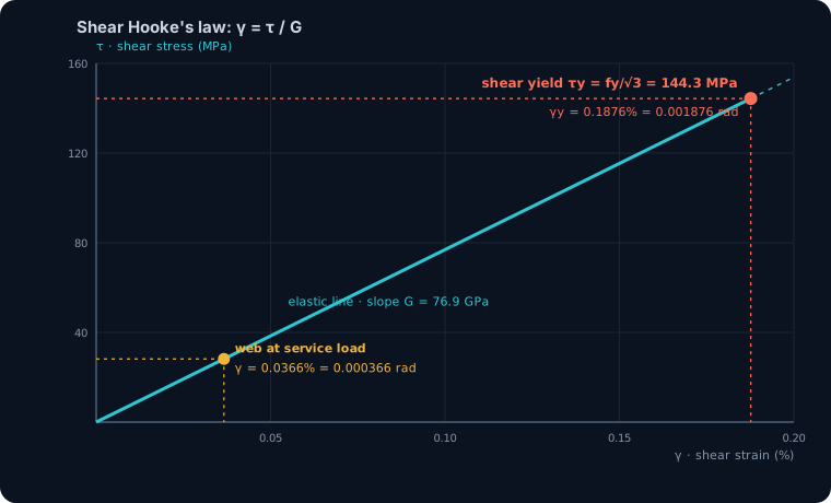
Here is the definition worth memorising: shear strain is the change in a right angle inside the material, measured in radians. Picture a tiny square drawn on the side of a loaded beam web. Apply shear stress and that square racks over into a parallelogram; the corners that were 90 degrees are now slightly more or slightly less. The amount of that change, in radians, is the shear strain γ.
Geometrically, if the top face slides a distance Δx relative to the bottom face a height L away, then γ = Δx / L. For the small angles that structures actually experience, that ratio equals tan γ which equals γ itself in radians, so the three are interchangeable. This is why γ is dimensionless: it is a length divided by a length, or equivalently an angle. Engineers quote it three ways, exactly as with normal strain: as a decimal (0.000366), as a percent (0.0366%), or in microradians (366 µrad), where one microradian is a millionth of a radian.
Two consequences follow immediately. First, γ has nothing to do with volume change or stretching; a body in pure shear keeps its volume and only distorts its shape. Second, because it is an angle, a γ of one full radian would be enormous, about 57 degrees of racking. Real structural shear strains are a few hundred microradians, which is why the distortion is invisible to the eye even as the material works hard.
The shear strain formula: γ = τ / G
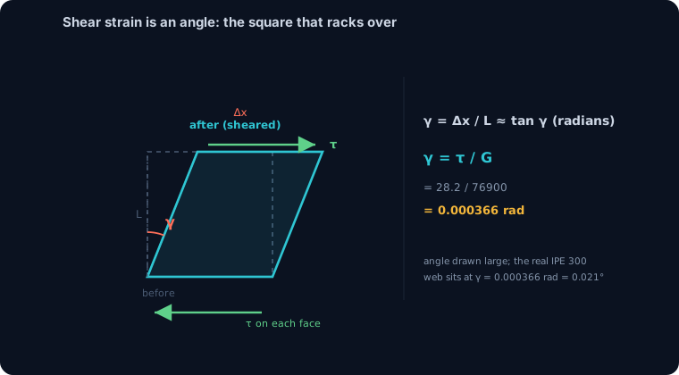
The formula itself is Hooke's law written for shear. In the elastic range the shear stress and the shear strain are proportional, τ = G·γ, so rearranged the shear strain formula is γ = τ / G. It is the exact structural analogue of ε = σ / E: swap the normal stress σ for the shear stress τ and the elastic modulus E for the shear modulus G, and you have it.
Every quantity has a clear meaning. τ is the shear stress on the plane you care about, in MPa. G is the shear modulus, also called the modulus of rigidity, in MPa or GPa. And γ is the resulting shear strain in radians. Read the formula out loud and it says something intuitive: a stiffer material (larger G) distorts less for the same shear stress, and a higher shear stress distorts more for the same material.
One caution that trips up students and shows up in exam questions: there are two definitions of shear strain in circulation. The engineering shear strain γ used in every design formula is the full change in the right angle. The tensorial shear strain εxy that appears in continuum mechanics and finite-element output is exactly half of it, εxy = γ / 2. They differ by a factor of two, and mixing them is a classic error. When you use γ = τ / G you are using the engineering definition, which is the one that pairs with G.
Where G comes from: G = E / 2(1+ν)
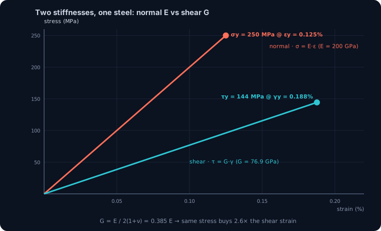
The shear modulus is not a free, independent number you look up in isolation. For an isotropic material like structural steel it is locked to the two properties you already know, the elastic modulus E and Poisson's ratio ν, by G = E / 2(1+ν). Steel has E = 200 GPa and ν = 0.3, so G = 200 / (2 · 1.3) = 76.9 GPa. That is the exact value the CalcSteel engine carries for every hot-rolled grade (G = 7692 kN/cm²), and it is why you rarely need to tabulate G separately: it falls out of E and ν.
That relationship carries a useful design intuition. Because 1 / 2(1+ν) works out to 0.385, the shear modulus is only about 38.5% of the elastic modulus. Steel is markedly softer in shear than in tension. Put the two Hooke's laws side by side at the same stress and the shear strain is E / G = 2.6 times the normal strain: a given stress buys 2.6 times more angular distortion than it buys stretch. The catch, which the worked example below makes concrete, is that the web usually sees far less stress than the flange, so the actual shear strain still ends up smaller than the actual bending strain even though shear is the softer mode.
A note for the standard-conscious: Eurocode 3 adopts E = 210 GPa, which pushes G to 80.8 GPa (the engine's S-grade value, 8077 kN/cm²). Same physics, a 5% shift in the number, and a reminder that G, like the yield strain we cover in a companion article, inherits whatever E your code declares.
Where it shows up (1): shear in a real beam web
Time to make γ concrete on steel you would actually specify. Take the same beam we metered for bending strain in yield strain: a simply supported IPE 300 spanning L = 6 m under a uniform load w = 20 kN/m, a routine floor beam. We model it in the CalcSteel FEM engine, the same solver behind the calculators, and read the shear rather than assume it.
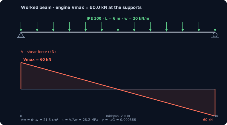
The engine returns a maximum shear force Vmax = 60.0 kN at each support, matching the hand value wL/2 = 20·6/2 = 60.0 kN exactly. Shear is largest at the supports and falls linearly to zero at midspan, the mirror image of the bending moment, which peaks where the shear crosses zero (the relationship we unpack in shear force and bending moment diagrams). In an I-section that shear is carried almost entirely by the web, so the shear area is Aw = d·tw = 30.0 · 0.71 = 21.3 cm², the overall depth times the web thickness, the same definition AISC uses for I-shapes.
Worked check: the web's shear strain
Now turn that shear force into a shear strain with the formula. The average web shear stress is τ = V / Aw. In consistent units, τ = 60 kN / 21.3 cm² = 2.817 kN/cm² = 28.2 MPa. Apply the shear strain formula: γ = τ / G = 28.2 / 76900 = 0.000366 rad, that is 0.0366%, or 366 µrad, an angular racking of 0.021 degrees.
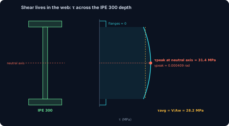
The distribution is not uniform. Shear stress across an I-section is tiny in the flanges and concentrated in the web, peaking at the neutral axis. Running τ = VQ/(I·tw) at the neutral axis with the engine's section properties (Ix = 8097 cm⁴) gives a peak of 31.4 MPa, about 1.12 times the average, so the peak fibre shear strain is γpeak = 0.000409 rad (409 µrad). This is the physical reason steel beams almost never fail in web shear before they fail in bending: the shear demand spreads over the whole web, while bending piles onto the extreme fibre.
The comparison that makes the point is with the same beam's bending. In the yield-strain article, this exact IPE 300 under this exact load reached an outer-fibre bending stress of 166.7 MPa and a normal strain of ε = 0.000834. So on one member, at one load, the flange bending strain is 0.000834 while the web shear strain is 0.000366: the shear strain is only 44% of the bending strain. Shear is the softer mode per unit stress, but the web simply is not stressed as hard as the flange, so it strains less. That single sentence is most of what you need to know about where shear does and does not govern.
See it yourself: read V, then divide by the web
You can reproduce the worked numbers in the calculator below. Set a simply supported span with a uniform load and read the shear force V it reports at the support. Then the shear strain is two short steps away: divide V by the web area Aw = d·tw to get the average shear stress τ, then divide τ by 76,900 MPa to get γ. Change the span or the load and watch V, and therefore γ, move with it.
Try the experiment that makes the theory click: hold the load fixed and shorten the span. The shear force barely changes, but the bending moment falls with L², so the beam shifts from bending-governed toward shear-governed. That is the crossover the next section quantifies. It is the same FEM engine that produced the numbers above, free, with no login for the maths.
Max moment
45 kN·m
Max shear
30 kN
Max deflection
10.55 mm
= L/569
Bending stress σ
84.4 MPa
σ = M/Sx
Utilization
44.0%
NBR 8800 · δ ≤ L/250
Geometry & supports
Section
Ix 7999 cm⁴ · Sx 533 cm³ · 42.2 kg/m
Point loads (↓ positive)
None — add as many as you need.
Distributed loads (uniform or trapezoidal)
Model sketch
Diagrams — free PNG / SVG / CSV export, no watermark
Step-by-step — the calculation memory of YOUR beam
IPE 300 · L = 6 m · fy = 250 MPa
1. Reactions (equilibrium of the solved FEM model)
ΣFy = 0 · ΣM = 0
R_A = 30 kN · R_B = 30 kN
2. Peak shear (read from the SFD)
Vmax = |V(x)|max
Vmax = -30 kN @ x = 6 m
3. Peak moment (read from the BMD)
Mmax = |M(x)|max
Mmax = 45 kN·m @ x = 3 m
4. Peak deflection
EI = 15998 kN·m² (E = 200 GPa)
δmax = 10.55 mm @ x = 3 m = L/569
5. Elastic bending stress
σ = Mmax / Sx = 45.00 × 10³ / 533.3
σ = 84.4 MPa
6. Bending check — both codes, side by side
NBR 8800: σ ≤ fy/1.10 = 227.3 MPa · AISC 360: σ ≤ 0.90·fy = 225 MPa
NBR 37.1% PASS · AISC 37.5% PASS
7. Deflection check (serviceability — code-independent)
δ ≤ L/250 = 24 mm
10.55 mm / 24 mm = 44.0% PASS
Recomputed live from the current inputs by the direct-stiffness FEM engine — change any load and every step updates. Reproduce it by hand with the formulas in the sections below.
Lightest catalog profiles that pass (974 flexural candidates · NBR 8800)
| Profile | Std | Weight | Total steel | σ util | δ util | |
|---|---|---|---|---|---|---|
| W310x21 | AISC | 21 kg/m | 126 kg | 83% | 98% | |
| VS 300x23 | BR | 22.6 kg/m | 136 kg | 71% | 84% | |
| U 300x90x6.3 | BR | 23.1 kg/m | 139 kg | 82% | 98% | |
| U 300x100x6.3 | BR | 24.1 kg/m | 145 kg | 77% | 91% | |
| VS 250x25 | BR | 24.6 kg/m | 148 kg | 70% | 100% |
Elastic bending (σ = M/Sx vs fy/γa1, γa1 = 1.10 — NBR 8800) + deflection screening of the full flexural catalog. Lateral-torsional buckling, shear and local buckling are NOT checked here — run the full NBR 8800 / AISC 360 verification in the 3D editor.
How far from yield? the shear-strain margin
A strain is only meaningful against the strain at which the material gives up. Steel does not have a separately measured shear yield; it is derived from the tensile yield by the von Mises criterion, τy = fy / √3. For MR250 (fy = 250 MPa) that is 144.3 MPa, and design codes round it to 0.6·fy = 150 MPa. The shear strain at yield is γy = τy / G = 144.3 / 76900 = 0.001876 rad (0.1876%).
Against that, the worked web at 28.2 MPa sits at just 28.2 / 144.3 = 19.5% of shear yield. Compare this with the same beam's bending, which reached 67% of its yield strain in the yield-strain article, and the message is clear: this beam is more than three times further from yielding in shear than in bending. Push the load up and the engine confirms it, the web reaches first shear yield only at w = 102 kN/m (V = 307 kN), whereas the flange reaches first bending yield at just w = 30 kN/m. Bending governs, comfortably, exactly as it should for a slender L/d = 20 beam. Shear strain is the junior partner here, and web-shear checks pass so easily on rolled beams that many designers forget to run them, which is fine until the member gets short and deep.
Where it shows up (2): shear strain adds to deflection
Shear strain does not only threaten strength; it quietly adds to how much a beam sags. A classic Euler-Bernoulli analysis, the one the engine uses for the reported deflection, assumes plane sections stay plane and ignores shear distortion. Reality adds a shear component on top of the bending one, because every slice of web is racking through its own little γ.
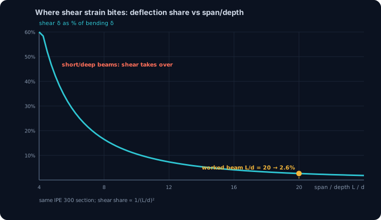
For the worked beam the split is: the bending deflection is 2.084 cm (the L/288 the engine reports), and the shear deflection from all that web γ is 0.055 cm, about 2.6% on top. Small, and safely ignorable here. But the shear share scales as 1/(L/d)², so it climbs fast as a beam gets stubbier: halve the span and it quadruples. By L/d = 8 it is around 16%, and for a deep transfer girder or a coupling beam at L/d = 4 it approaches half the total deflection. This is why deep short members, plate girders and the like are analysed with Timoshenko beam theory that carries shear strain explicitly, while the slender floor beams of everyday framing get away with ignoring it. See deflection limits for how the total sag then gets checked.
Where it shows up (3): bolts, panel zones and shear studs
Beyond beam webs, shear strain is the whole story in the parts of a frame that exist to transfer load sideways.
- Bolts and welds. A bolt in a lap splice is loaded almost purely in shear; the shank distorts through γ = τ / G until it either stays elastic or yields on the shear plane. Bolt-group design is a shear-strain problem wearing a capacity check.
- Moment-connection panel zones. The column web between the beam flanges of a moment connection is a square of steel loaded in near-pure shear. Its γ is often large enough to matter, and seismic design deliberately lets the panel zone yield in shear to dissipate energy, spending shear strain the way ductile design spends the plastic plateau.
- Shear studs and connectors. The studs that make a steel beam act compositely with a concrete slab work in shear at the interface, straining through γ to drag the two materials into cooperation.
- Torsion. Twist an open or closed section and the walls carry shear stress and shear strain; the angle of twist is nothing but accumulated γ around the section.
In every one of these, the shear strain formula γ = τ / G is the bridge from the force you can compute to the distortion the detail actually undergoes.
Common mistakes and FAQ
Confusing engineering and tensorial shear strain. The design γ is the full angle change; the tensorial εxy in FE output is half of it. Off by a factor of two if you mix them.
Using E instead of G. Shear strain uses the shear modulus, γ = τ / G, not γ = τ / E. Since G is only 38.5% of E, that mistake underestimates γ by a factor of 2.6.
Averaging shear over the whole area. For an I-section the shear is carried by the web, not the flanges, so divide by Aw = d·tw, not the gross area A. Using A would understate the web stress badly.
Reading γ as a stretch. γ is an angle, in radians. It is not a change in length and it does not, on its own, change the member's length.
Is the shear strain formula the same for all materials? γ = τ / G holds for any linear-elastic isotropic material; only G changes. For steel G ≈ 76.9 GPa, for aluminium about 26 GPa, for concrete around 10 to 15 GPa.
Why is G always smaller than E? Because G = E / 2(1+ν) and ν is positive (0.3 for steel), the denominator exceeds two, so G is always well below E. No isotropic material is stiffer in shear than in tension.
What is a typical shear strain in a steel beam? A few hundred microradians in service, as the worked web showed (366 µrad), rising toward the ~1900 µrad of shear yield only in heavily loaded webs and connections.
Key takeaways
Shear strain is the angular half of Hooke's law, and once you have the formula it is as routine as its axial cousin.
- The shear strain formula is γ = τ / G, an angle in radians, the change in a right angle inside the material.
- G is not independent: G = E / 2(1+ν) = 0.385·E for steel, so G ≈ 76.9 GPa and a given stress buys 2.6 times the shear strain of a normal strain.
- Worked IPE 300 (L = 6 m, w = 20 kN/m): the engine gives Vmax = 60.0 kN, so the web carries τ = 28.2 MPa and γ = 0.000366 rad, 44% of the bending strain and 20% of shear yield.
- Shear strain also drives deflection, bolt slip and panel-zone distortion; it is 2.6% of the sag on this slender beam but grows as 1/(L/d)² and governs short, deep members and connections.
- Engineering γ is twice the tensorial εxy, and it always uses G, never E: the two most common ways to get shear strain wrong.
Sources
- 1.AISC 360-16, Specification for Structural Steel Buildings (Chapter G, shear; shear modulus G)
- 2.Eurocode 3 (EN 1993-1-1) §6.2.6 shear resistance and §3.2.6 material constants (E, G, ν)
- 3.Gere and Goodno, Mechanics of Materials (shear stress, shear strain and Hooke's law in shear)
- 4.Timoshenko and Goodier, Theory of Elasticity (isotropic relation G = E / 2(1+ν))
- 5.ABNT NBR 8800, Projeto de estruturas de aço e de estruturas mistas de aço e concreto
Try CalcSteel for free
Model, analyze and design steel structures in your browser. No install, no signup.
Open the 3D editor