Shear Centre and Torsion: Why an Open Section Twists When You Did Not Ask It To
Put a load right over the web of a channel and the channel still twists. It twists because a transverse load bends a section without twisting it only when it passes through one special point, the shear centre, and for an open section like a channel that point is not the centroid. It is not even inside the section. The gap between where you applied the load and where the shear centre actually is turns the load into a torque, and an open section is so weak in torsion that a modest load can rotate it alarmingly. Here is the whole story worked on one plain channel: where its shear centre is, the torque you did not ask for, and how far it twists, every number computed by the real CalcSteel engine and checked against thin-wall theory to three decimals.
Key takeaways
- A transverse load produces bending without twisting only when its line of action passes through the shear centre. For a channel the shear centre sits outside the section, behind the web. Our plain 200x75x6 channel has it 24.84 mm behind the web, checked in the CalcSteel engine.
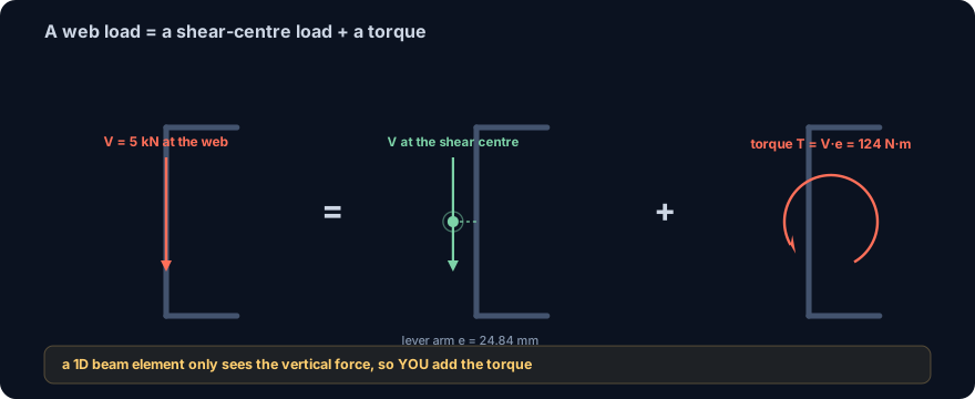
- Load the same channel through the web instead and the offset e turns the 5 kN load into a torque T = V e = 124 N·m. The frame model will not warn you: a 1D beam element carries the load on its reference line, so you have to add the torque yourself.
- An open section is feeble in torsion. Its St. Venant constant J = t3 L / 3 is tiny (2.43 cm4 here), so the 3 m cantilever twists 11.40 degrees, computed by the CalcSteel FEM engine and matching T L / (G J) to three decimals. Loaded through the shear centre it twists zero.
- Close the section and the weakness vanishes. A square tube of the same weight has J = 356 cm4, about 146 times stiffer in torsion. That is why you box, cap or restrain an open section rather than let it twist.
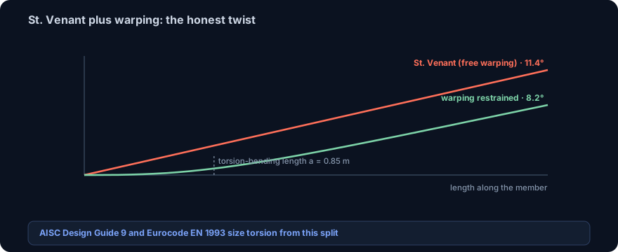
- The pure St. Venant number is an upper bound. A real member whose end is restrained against warping twists less, here about 8.2 degrees (72 percent), governed by the torsion-bending length. That warping term is exactly what AISC Design Guide 9 and Eurocode EN 1993 add on top.
The load you put right over the web, and it still twisted
Take a plain steel channel, lay it out as a beam, and hang the load carefully over the web, right down the middle of the back of the C, where any reasonable person would put it. Now watch it. The channel does not just sag. It rolls over as it bends, the flanges swinging out of plane, the whole section rotating along its length. You did not apply a twist. The load was vertical and you aimed it at the web. And yet the section is twisting.
This is not a defect in the steel or a mistake in your loading. It is the single most surprising fact about open cross sections, and it catches students, and plenty of practising engineers, off guard. A transverse load bends a member without twisting it only if the load passes through one particular point of the cross section, the shear centre. For the doubly symmetric shapes you meet first, the wide-flange beam, the square tube, the shear centre sits on the centroid and you never have to think about it. For a channel, an angle, a tee, a zed, any open, singly symmetric or asymmetric section, it moves. For a channel it moves clean outside the section, into thin air behind the web.
This article works the whole thing on one channel, and every number in it was produced by the shipping CalcSteel engine and checked against classical thin-wall theory to three decimals. We find where the shear centre is, we turn the offset into the torque it really is, and we let the section twist and measure it. If you have read our guide to shear force and bending moment diagrams, this is the third internal action those diagrams leave out, and the one that decides whether an open section survives being loaded off centre.
What the shear centre actually is
The shear centre is the point in a cross section through which a transverse load must pass to cause bending with no twist. Equivalently, it is the point about which the internal shear stresses have zero net moment. Apply your load there and the member bends in pure flexure; apply it anywhere else and the load is statically equivalent to the same load moved to the shear centre plus a torque equal to the load times the offset. Torsion is not an extra action you add. It is what a transverse load becomes the moment it misses the shear centre.
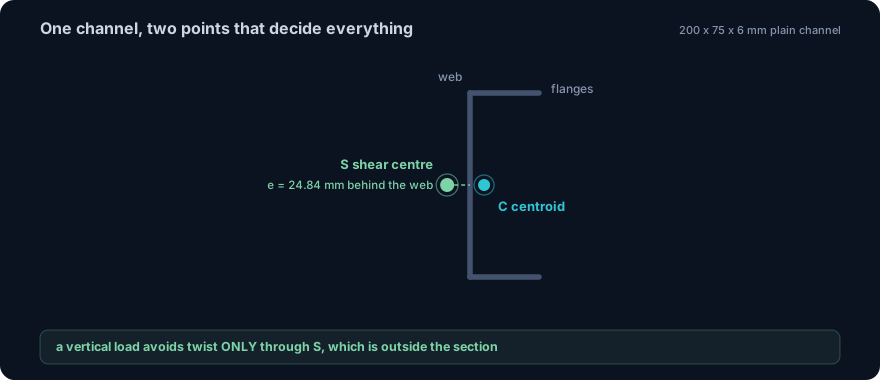
Two facts about its location do almost all the work. First, the shear centre always lies on any axis of symmetry, because the shear stresses are symmetric about that axis. A channel loaded vertically is symmetric about its horizontal axis, so its shear centre is somewhere on that horizontal line, left or right of the web. Second, for a section built from thin plates that all meet at a point, an angle or a tee, the shear flow in every plate passes through that meeting point, so the shear centre sits right at the corner, or at the junction of flange and stem. For those two shapes the shear centre is easy to see. For a channel it takes one short calculation, and the answer is genuinely counterintuitive: it is not between the flanges, it is behind the web.
Where the channel's shear centre is, and why it is outside
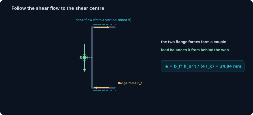
Follow the shear, and the offset falls out. When a channel carries a vertical shear V, a shear flow runs along its walls, and in the two flanges that flow is horizontal. It builds from zero at each flange tip to a maximum at the web, and integrating it gives a horizontal force in each flange, Ff, one pointing in, one pointing out. Those two flange forces are equal, opposite, and separated by the web depth, so together they form a couple. The web itself carries the vertical shear V. For the section to be in equilibrium without twisting, the applied load V must produce a moment about the web that exactly balances that flange couple, and that condition places it at a specific horizontal distance e from the web:
e = bf2 ho2 t / (4 Ix)
where bf is the flange width to the web centreline, ho the distance between flange centrelines, t the thickness, and Ix the second moment of area about the axis of bending. The flange couple sits entirely on the flange side of the web, so the balancing load has to sit on the other side, behind the web, which is why the shear centre lands outside the material. For our channel, bf = 72 mm, ho = 194 mm, t = 6 mm and Ix = 1178 cm4, giving e = 24.84 mm behind the web. The flanges are only 75 mm wide, so the shear centre is about a third of a flange width past the back of the section, in open air.
The section, computed in the engine
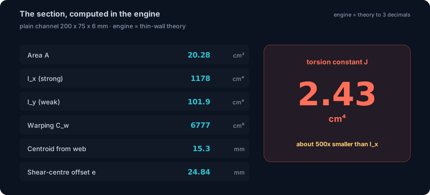
Everything downstream, the torque, the twist, the comparison with a closed section, rides on the section properties, so we pin them down first with the real engine. The member is a plain channel, 200 mm web, 75 mm flanges, 6 mm thick, no lips, the textbook torsion example. The CalcSteel section engine returns, and closed-form thin-wall theory confirms to three decimals:
- Area A = 20.28 cm2
- Strong-axis inertia Ix = 1178 cm4, weak-axis Iy = 101.9 cm4
- Centroid 15.3 mm in front of the web (toward the flanges)
- St. Venant torsion constant J = 2.43 cm4
- Warping constant Cw = 6777 cm6
Read that torsion constant again. For an open thin-walled section J is just J = t3 Lm / 3, the cube of the thickness times the developed length of the walls, over three. Here that is 0.63 times 33.8 cm over 3, or 2.43 cm4. Compare it to the bending inertia Ix of 1178: the section is roughly five hundred times stiffer in bending than in torsion. That single number, J = 2.43 cm4, is the reason the rest of this article is a cautionary tale. Note too that J is not the polar moment of inertia Ix + Iy; using the polar moment for open-section torsion overestimates the stiffness by orders of magnitude and is a classic, expensive mistake.
The torque you did not ask for
Now load it. A modest transverse service load, V = 5 kN, applied in the plane of the web, exactly where you would bolt a beam down or rest a load on the back of the channel. The web line sits a distance e = 24.84 mm from the shear centre. By the definition from two sections ago, that load is statically identical to the same 5 kN applied at the shear centre, which causes pure bending, plus a torque about the shear centre:
T = V · e = 5 kN · 24.84 mm = 124 N·m
A hundred and twenty-four newton metres, from a load you thought was purely vertical, purely central, purely harmless. And here is the trap that makes this a design problem rather than a curiosity: your analysis model will not tell you. A one-dimensional beam or frame element, the kind every structural solver is built from, carries its loads on the member reference line and keeps bending and torsion in separate, uncoupled channels. It has no idea the real section's shear centre is 24.84 mm to one side. Feed it a vertical load and it returns a clean bending result with zero twist, looking perfectly healthy. The shear-centre offset is a property of the cross section, and it is on you, not the solver, to convert the eccentric load into the force-plus-torque the member actually feels. Get that conversion right and the torque appears; skip it and it hides.
Case A: load through the shear centre, no twist
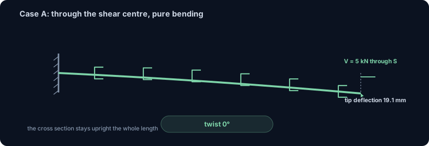
To see the two halves cleanly, we run the channel as a 3 m cantilever in the CalcSteel FEM engine, fixed at one end, and load the tip two ways. Case A is the baseline: the 5 kN load applied through the shear centre, the point that produces bending and nothing else.
The engine returns exactly what the definition promises. The tip twist is zero. The member is in pure flexure, deflecting 19.1 mm at the tip under the 5 kN load, bending about its strong axis with Ix = 1178 cm4, and every fibre is carrying nothing but the flexural stress you would expect from the bending moment diagram. This is the state you assumed you were in when you drew the load over the web. It is achievable, but only by aiming the load at a point 24.84 mm behind the web, which for a real load path usually means adding a bracket, a cap plate, or a second channel to carry it. Load a bare channel anywhere else and Case A is not what you get.
Case B: load through the web, the section twists
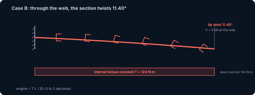
Case B keeps the same 5 kN load and the same cantilever, but applies the load through the web, where it really lands. By the equivalence, that is the shear-centre load of Case A plus the torque T = 124 N·m running the full length of the member. The bending is unchanged; the new ingredient is the twist.
The CalcSteel engine twists the tip 11.40 degrees. The internal torque is constant at 124 N·m along the whole cantilever, and the reaction at the fixed base is an equal and opposite 124 N·m torque, closing equilibrium. Every one of those numbers matches the closed-form St. Venant result φ = T L / (G J) to three decimals, using the engine's own J = 2.43 cm4 and steel's shear modulus G = 76.9 GPa. Eleven degrees. From five kilonewtons, applied down the middle of the web, on a member you sized comfortably for bending. Put the strong-axis deflection of 19.1 mm next to an eleven-degree roll and you can see why an unrestrained channel loaded off its shear centre is not a serviceability nuisance but a stability and stress problem: the rotation throws the flanges sideways, the load path skews, and the flexural stresses you designed for are now riding on top of torsional ones.
Why open sections are the victims, and closed ones are not
The twist is not really about the shear centre. The offset created the torque, but what turned a small torque into eleven degrees was the section's torsional weakness, and that is a property of being open. An open section resists twist only through St. Venant torsion, the thin walls shearing along their length, and its constant J = t3 Lm / 3 scales with the cube of a small thickness, so it is always tiny. A closed section resists twist by running a continuous shear flow around the cell, the Bredt mechanism, and its J scales with the enclosed area squared, which is enormous by comparison.
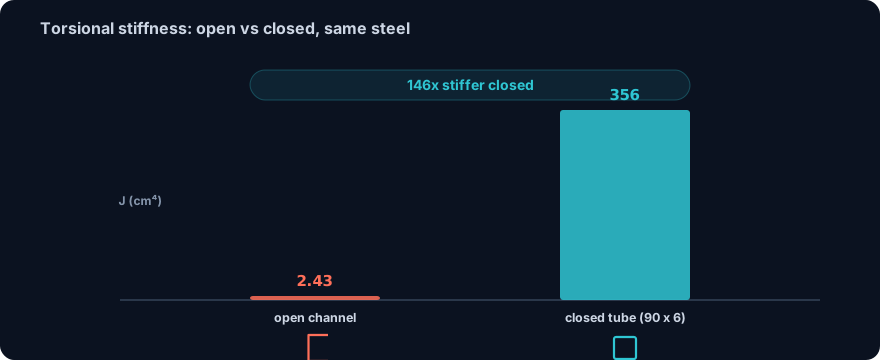
Put numbers on it. Take a square hollow section of the same weight as our channel, a 90x6 tube with essentially the same 20 cm2 of steel. The engine gives it J = 356 cm4, against the channel's 2.43. That is about 146 times stiffer in torsion for the same steel. Under the same 124 N·m torque the tube would twist not eleven degrees but under a tenth of one. This is the whole practical lesson in one ratio: if a member has to carry torsion, close it. When you cannot close it, the design moves become familiar for exactly this reason, load through the shear centre with a bracket, add a plate to box the open section, or restrain it against rotation at close enough intervals that it never accumulates a twist like this one. It is also why lateral-torsional buckling, the sideways-plus-twist failure of an unbraced beam, is a story about open sections and hardly ever about tubes.
The honest correction: warping, and the criterion behind the code
One caveat keeps the eleven degrees honest. The formula φ = T L / (G J), and the CalcSteel frame engine that reproduces it, model pure St. Venant torsion, in which every cross section is free to warp out of plane as it twists. Restrain that warping, by welding the end down, bolting it to a stiff support, anything that stops the flanges sliding along the member axis, and a second, stiffer mechanism switches on: warping torsion, where the flanges bend in their own plane and resist the twist through their bending stiffness E Cw. A real member usually has some warping restraint, so its true twist is less than the free-warping value.
How much less is set by one length, the torsion-bending constant a = √(E Cw / G J). For our channel that is 0.85 m. Warping restraint dies out over roughly that distance from the restrained end, so if the member is many times longer than a, St. Venant dominates and the free-warping number is close; if it is only a few times a, warping cuts the twist noticeably. Our cantilever is 3 m, so L / a = 3.5, and working the restrained-warping solution the tip twist comes to about 8.2 degrees, 72 percent of the free-warping 11.4. Still a large, unacceptable rotation, but meaningfully smaller, and the difference is real. This is the criterion behind the code: open-section torsion is treated as St. Venant plus warping, and the design standards give you the warping term explicitly. AISC Design Guide 9, Torsional Analysis of Structural Steel Members, is built entirely around this split; Eurocode EN 1993-1-1 with EN 1993-1-3, and ABNT NBR 8800 with NBR 14762 for cold-formed sections, carry the same two-part torsion. The frame engine gives you the St. Venant upper bound to size against; the code's warping term is how you claim the rest back when the end is genuinely restrained.
Try it: build the channel and read its properties
The calculator below is the same section engine used for every number above. Build the plain 200x75x6 channel, or any channel you like, and read its area, its strong and weak inertias, its section modulus and its centroid, drawn to scale and matched live against the CalcSteel profile database. Watch what happens to the torsion constant J as you change the thickness: because J goes with t3, shaving a millimetre off the wall guts the torsional stiffness far faster than it touches the bending inertia. Compare an open channel against a closed tube of similar size and you will see the same hundred-fold gap in J we found above.
It is free and needs no login. Once you have the section in front of you, the shear-centre offset and the torque T = V e are one short step away, and the twist follows from T L / (G J) with the J the tool just handed you.
Formula — hover a variable to highlight it on the drawing
Ix = [ b·h³ − (b − tw)·hw³ ] / 12= 1,845.6 cm⁴(hw = h − 2·tf)
Iy = [ 2·tf·b³ + hw·tw³ ] / 12= 141.9 cm⁴
Root fillets are neglected — rolled-section tables run 1–5% higher on Ix.
Parallel-axis theorem, live — Ix = Σ ( I₀ + A·d² )
| Part | A (cm²) | d (cm) | I₀ (cm⁴) | A·d² (cm⁴) | I₀ + A·d² (cm⁴) |
|---|---|---|---|---|---|
| Web | 10.25 | 0 | 286 | 0 | 286 |
| Flange (top) | 8.5 | 9.58 | 0.512 | 779.3 | 779.8 |
| Flange (bottom) | 8.5 | 9.58 | 0.512 | 779.3 | 779.8 |
| Σ = Ix | 287 | 1,558.6 | 1,845.6 |
Exact rectangle parts (web + two flanges) about the section centroid — the flange A·d² transfer terms are the whole story of the I-beam. Change any dimension above and watch the table re-derive.
Section properties
Moment of inertia Ix
1,845.6 cm⁴
1.846 × 10⁷ mm⁴
Moment of inertia Iy
141.9 cm⁴
1.419 × 10⁶ mm⁴
Area A
27.25 cm²
Mass
21.39 kg/m
Section modulus Sx
184.6 cm³
Section modulus Sy
28.39 cm³
Plastic modulus Zx
209.7 cm³
Plastic modulus Zy
43.93 cm³
Radius of gyration rx
8.23 cm
Radius of gyration ry
2.28 cm
Centroid x̄ (from left)
50 mm
Centroid ȳ (from bottom)
100 mm
Local slenderness — NBR 8800 / AISC 360 fingerprint
Flange
λ = b / 2·tf = 5.88
λp = 10.75 · λr = 28.28
Web
λ = hw / tw = 32.68
λp = 106.3 · λr = 161.2
Flexure limits per AISC 360 Table B4.1b (≈ NBR 8800 Annex F), fy = 250 MPa, E = 200 GPa — λp/λr scale with √(E/fy). Compact sections reach the full plastic moment Mp = Z·fy; non-compact and slender elements are capped by local buckling.
Closest standard profiles — matched by Ix against 876 real catalog sections
Ix = 1,845.6 cm⁴ (-0.0%)
Iy = 141.9 cm⁴ (-0.0%)
21.39 kg/mlightest
Best match — design checks
Ix = 1,844.2 cm⁴ (-0.1%)
Iy = 902.5 cm⁴ (+535.8%)
34.19 kg/m#2 by weight
Design checks
Ix = 1,838.7 cm⁴ (-0.4%)
Iy = 1,838.7 cm⁴ (+1195.4%)
43.96 kg/m#3 by weight
Design checks
Same 1,309-profile database that powers the CalcSteel 3D editor and profile pages — ABNT cold-formed (Ue, U, rounds), AISC (W, HSS, L, Pipe), European (IPE, HEA, HEB, HEM, UPN) and Indian (ISMB/ISMC) series. Opening a match carries your custom section along as the comparison baseline.
How to check an open section for the twist you did not design
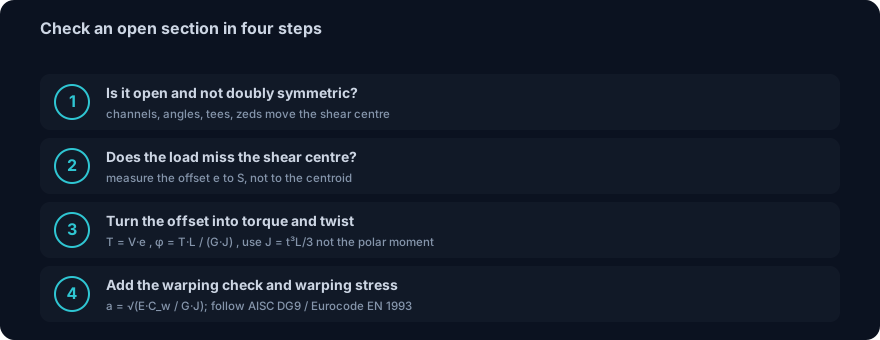
You will not hand-solve every member, but on any open section carrying a transverse load, four checks in order catch the twist before it reaches the drawing.
1. Is the section open and not doubly symmetric? Wide-flange beams and tubes put the shear centre on the centroid, so a centroidal load is safe. Channels, angles, tees, zeds and any singly symmetric or asymmetric open shape move the shear centre, and a channel moves it outside the section. If the shape is on that list, the shear centre is not where you think, so find it.
2. Does the load line miss the shear centre? Measure the offset e from the actual line of action to the shear centre, not to the centroid. For our channel a web-line load is 24.84 mm off. Zero offset, no torsion; any offset, keep going.
3. Turn the offset into a torque and a twist. T = V e is the torque, constant along a simply loaded member, and φ = T L / (G J) is the free-warping twist, your upper bound. Use the section's real J = t3 Lm / 3, never the polar moment. If the number is alarming, it is supposed to be.
4. Add the warping check, and the warping stress. If the ends are restrained, compute a = √(E Cw / G J) and reduce the twist accordingly, following AISC Design Guide 9 or Eurocode EN 1993. Torsion of an open section also adds a warping normal stress in the flanges that stacks on top of bending, much as an axial force stacks on bending in the combined axial and bending check. Add it in before you call the section adequate.
Common mistakes and FAQ
Assuming a load through the centroid causes no twist. The most common error, and the whole reason for this article. Bending is measured about the centroid; twist is measured about the shear centre. For an open section they are different points, and a centroidal load twists.
Looking for the channel's shear centre between the flanges. It is behind the web, outside the section, on the side away from the flanges. Nothing you can see marks the spot, which is exactly why it gets missed.
Using the polar moment of inertia for torsion. For a solid or closed section the torsion constant is close to the polar moment; for an open section it is not, it is t3 Lm / 3, smaller by orders of magnitude. Substitute the polar moment and you will predict a member a hundred times stiffer in torsion than it is.
Trusting the frame model's zero twist. A 1D beam element keeps bending and torsion uncoupled and knows nothing about the shear-centre offset, so it returns zero twist for a vertical load whatever the real section is. The twist is your responsibility to add, not the solver's to find.
Where is the shear centre of an angle or a tee? At the corner of the angle, or at the junction of flange and stem of the tee, because every plate's shear flow passes through that point. That also makes both shapes poor at resisting any load that misses the corner.
Does the twist depend on the steel grade? No. J, Cw and the twist depend on geometry and on the elastic constants E and G, which are essentially the same for all structural steels. A stronger grade does not twist less; only a stiffer or closed section does.
Is 11 degrees realistic, or a textbook exaggeration? It is the real St. Venant answer for this bare cantilever, and the warping-restrained value is still about 8. In practice you never let it get there, precisely because open sections twist this easily. The large number is the warning, not a mistake.
Key takeaways
- A transverse load bends without twisting only through the shear centre. For an open section it is not the centroid; for a channel it is outside the section, behind the web, 24.84 mm out for our plain 200x75x6, confirmed in the CalcSteel engine.
- Miss the shear centre by e and the load becomes a torque T = V e. Our 5 kN web-line load gives 124 N·m, and a 1D frame model will not warn you, because it carries the load on the reference line and keeps torsion uncoupled.
- Open sections are feeble in torsion: J = t3 Lm / 3 = 2.43 cm4 here, so the 3 m cantilever twists 11.40 degrees, computed by the FEM engine and matching T L / (G J) to three decimals. Loaded through the shear centre it twists zero.
- Close the section and the problem disappears: a same-weight square tube has J = 356 cm4, about 146 times stiffer. If a member must carry torsion, box it, cap it, or restrain it.
- The St. Venant twist is an upper bound. Warping restraint reduces it, here to about 8.2 degrees over a torsion-bending length a = 0.85 m, and that warping term is exactly what AISC Design Guide 9 and Eurocode EN 1993 add to size open-section torsion.
Sources
- 1.Gere and Timoshenko, Mechanics of Materials (shear centre of thin-walled open sections)
- 2.Boresi and Schmidt, Advanced Mechanics of Materials (torsion of open and closed sections, warping)
- 3.AISC Design Guide 9, Torsional Analysis of Structural Steel Members
- 4.Eurocode EN 1993-1-1 and EN 1993-1-3, Design of steel structures (torsion and cold-formed members)
- 5.ABNT NBR 8800 and NBR 14762, steel and cold-formed steel design
Try CalcSteel for free
Model, analyze and design steel structures in your browser. No install, no signup.
Open the 3D editor