Steel Rebar Calculator: Weight, Schedule & Bar Sizes
Calculate steel rebar weight in kg/m and lb/ft across NBR, ASTM and EN, build a bar schedule, and size a real FEM-designed beam — free, no login.
Key takeaways
- Every rebar weight comes from one formula — kg/m = 0.006165·d² — because a deformed bar's nominal mass is defined by its plain-round equivalent; the ribs don't count. A Ø16 bar is 1.578 kg/m in every code.
- Three standards, three labels, one physics: NBR 7480 (CA-50, Ø8–Ø32), ASTM A615 (#3–#18) and EN 10080 (Ø6–Ø40). A #4 bar is 0.668 lb/ft = 0.994 kg/m; 1 kg/m always equals 0.672 lb/ft.
- Total weight = unit mass × length × quantity, and a bar bending schedule is just that sum over every mark. The worked 6 m beam here totals 70.4 kg of steel.
- The design moment sets the steel, not the other way around: the CalcSteel FEM engine finds M = 135 kN·m on a 6 m beam, which needs 766 mm² → 4·Ø16 — and laps add another 5–15 % to the takeoff.
- Substitute bars by steel area, never by count: 5·Ø20 (1571 mm²) becomes 8·Ø16 (1609 mm²) for only +2.4 % extra weight, while As,min/As,max and development length keep the swap legal.
The weight of the world's most-used building material
Concrete is the second most consumed substance on Earth after water, and almost none of it stands up without steel inside it. The ribbed bars buried in every slab, beam, column and footing — reinforcement, or rebar — are what let concrete resist tension, and their weight is one of the first numbers a project turns on. It sets the material invoice, the number of trucks, the crane picks, the CO₂ estimate and the labour to tie it all. Get it wrong by ten percent and you have either over-ordered a fortune in steel or under-booked the delivery that holds up the pour.
The good news: rebar weight is one of the most calculable quantities in all of construction. Behind every bar-size chart and every online steel rebar calculator sits a single, exact formula, and a bar's mass never changes with the weather. The hard part isn't the arithmetic — it's doing it consistently across three different code systems, folding in laps and wastage, and connecting the tonnage back to the structural analysis that decided how much steel the member actually needed.
This guide is the complete walkthrough, and it goes the whole distance: from the one formula that fixes every unit mass, through the tri-standard size charts (Brazil's NBR 7480, America's ASTM A615, Europe's EN 10080), to a full bar bending schedule — and then the part most weight calculators skip. We take a real beam, run it through the CalcSteel finite-element engine to find its design moment, and turn that moment into an actual bar count and an actual weight. Every number below was computed by that engine or by the calculator's own mass routine and checked against the code formulas to three decimals.
The CalcSteel rebar weight calculator is embedded further down, free and with no login — it does the kg/m, the schedule, the code check and the cross-standard substitution as you read. Let's start with the formula that makes all of it possible.
The one formula behind every rebar weight
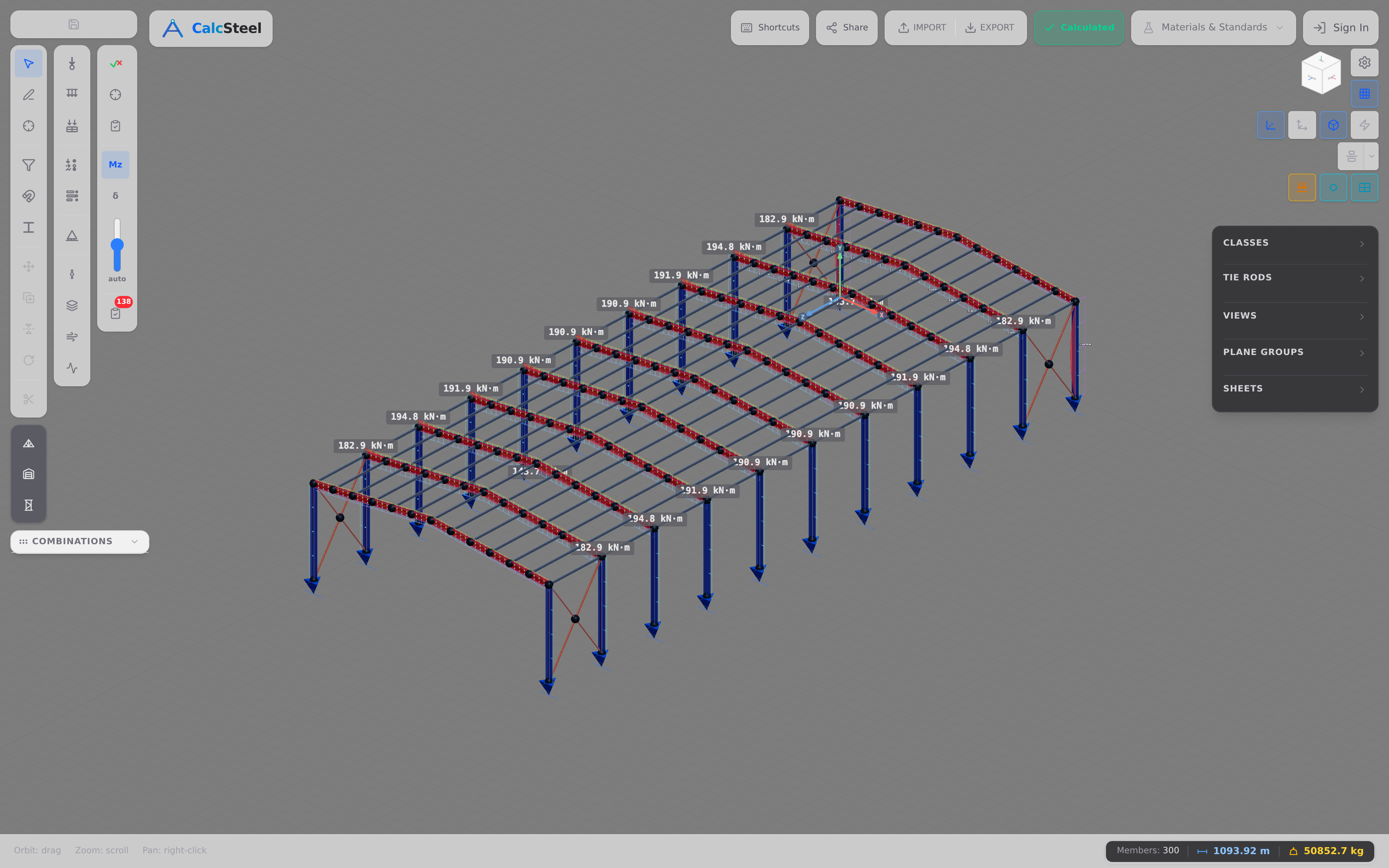
A reinforcing bar's nominal unit mass is the mass of the plain round bar of the same nominal diameter — the deformations (ribs) that grip the concrete are ignored. In SI units that is kg/m = (π/4)·d²·ρ·10⁻⁶ = 0.006165·d², with d the nominal diameter in millimetres and ρ = 7850 kg/m³ the density of carbon steel. That single expression reproduces every value in every national rebar table.
That is the whole of it. A bar labelled Ø16 is not weighed rib-by-rib; its nominal mass is defined from the equivalent smooth circle of 16 mm diameter. The cross-section area is A = π·d²/4 = π·16²/4 = 201 mm², and multiplying that area (in m²) by the steel density gives 201×10⁻⁶ × 7850 = 1.578 kg/m. Every standards body — ABNT, ASTM, CEN — publishes exactly this, rounded, in its bar table.
Two consequences matter in practice. First, because the nominal mass ignores the ribs, the same nominal diameter weighs the same in every code: a 16 mm bar is 1.578 kg/m in Brazil and in Europe alike — the labels can differ, the physics doesn't. Second, the mass grows with the square of the diameter, so stepping from Ø16 to Ø20 isn't 25 % more steel per metre, it's (20/16)² − 1 ≈ 56 % more. Doubling the diameter quadruples the weight. That quadratic is why bar selection is such a strong lever on tonnage.
When we validated the calculator's mass routine against the published nominal masses in NBR 7480, ASTM A615 and EN 10080, every value matched the 0.006165·d² formula to within the standards' own rounding (better than ±0.12 %). The formula isn't an approximation of the tables — it is the tables.
Rebar size charts: NBR, ASTM and EN side by side
The formula is universal, but the catalogue — which diameters are actually rolled and how they're named — is regional. Three systems cover most of the world, and a good steel rebar calculator has to speak all three, because a bar specified in one code is routinely bought, substituted or checked in another.
Brazil — ABNT NBR 7480 (CA-50)
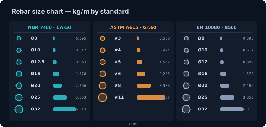
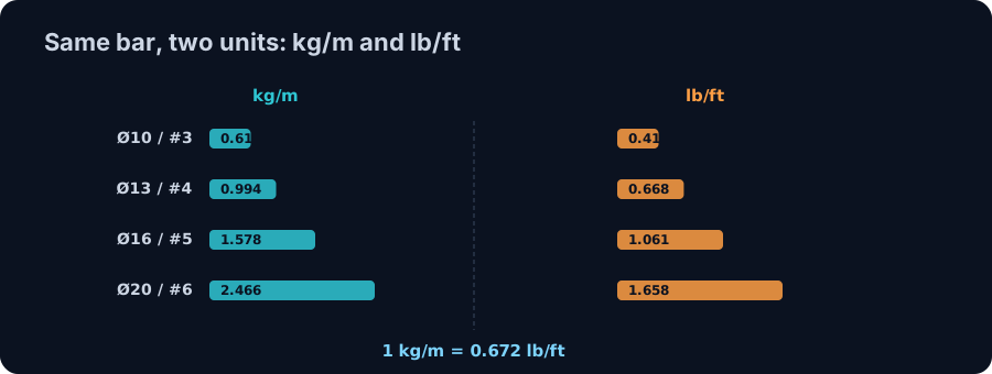
Named by nominal diameter in millimetres, in the preferred series Ø5.0, Ø6.3, Ø8.0, Ø10, Ø12.5, Ø16, Ø20, Ø25 and Ø32. The grade CA-50 means a characteristic yield of 500 MPa. Unit masses run from 0.154 kg/m (Ø5) to 6.313 kg/m (Ø32); the everyday structural sizes are Ø10 = 0.617 kg/m, Ø12.5 = 0.963, Ø16 = 1.578 and Ø20 = 2.466 kg/m.
United States — ASTM A615 / A615M (Grade 60)
Named by an imperial bar number that is (roughly) the diameter in eighths of an inch: #3 ≈ 3⁄8″, #4 ≈ 1⁄2″, up to #18. The authoritative figure is in pounds per foot, so #4 is 0.668 lb/ft, which converts to 0.994 kg/m; #8 (≈ 1″) is 2.670 lb/ft = 3.973 kg/m. Grade 60 is a 60 ksi (≈ 420 MPa) yield. American bars carry a soft-metric twin (#4 ↔ #13M) that trips up many spec conversions.
Europe — EN 10080 / ISO 6935-2 (B500)
Named by nominal diameter in the preferred series Ø6, 8, 10, 12, 14, 16, 20, 25, 28, 32 and 40, grade B500 (500 MPa yield). Because these are metric diameters, the masses coincide with the NBR values wherever the diameters match — Ø16 = 1.578 kg/m, Ø20 = 2.466, Ø32 = 6.313 — with Ø12 = 0.888 kg/m filling the gap between Brazil's Ø10 and Ø12.5.
The chart below lays all three out with their unit masses. Notice that the weights line up whenever the diameters do — the systems differ in labels and preferred sizes, not in the underlying steel. That is exactly why substituting across codes is an area problem, which we solve later.
kg/m, lb/ft and the total weight of a run
Two unit systems dominate rebar procurement, and mixing them up is the single most common source of a wrong tonnage. The metric world quotes kilograms per metre (kg/m); the United States quotes pounds per foot (lb/ft). They describe the same bar, and the bridge between them is one constant:
1 kg/m = 0.672 lb/ft, or inversely 1 lb/ft = 1.488 kg/m.
So the American #4 at 0.668 lb/ft is 0.668 × 1.488 = 0.994 kg/m; a European Ø20 at 2.466 kg/m is 2.466 × 0.672 = 1.658 lb/ft. Any honest rebar calculator lets you toggle the display without touching the underlying figure, because the nominal mass is a property of the steel, not of the units you print it in.
From unit mass to total weight
Once you have the unit mass, the total weight of a run of identical bars is trivial:
Total weight (kg) = unit mass (kg/m) × cut length (m) × quantity
A worked case: 100 bars of Ø10 CA-50, each cut to 12 m. The unit mass is 0.617 kg/m, so each bar is 0.617 × 12 = 7.404 kg, and 100 of them weigh 740.4 kg — most of a tonne from a single, modest bar mark. Turn the question around and you get the procurement view: one tonne of Ø10 in 12 m lengths is 1000 ÷ 7.404 ≈ 135 bars, or about 1621 metres of steel. Ordering, pricing and truck-loading all run off these two conversions.
The quadratic bites here too. The same 100 bars in Ø20 instead of Ø10 weigh 100 × 12 × 2.466 = 2959 kg — four times the tonnage for twice the diameter. Whenever you can satisfy the demand with more smaller bars instead of fewer large ones (within spacing rules), the weight often drops, which is the whole point of the substitution engine below.
The bar bending schedule: from one beam to a total
Real structures are never one bar mark. A single reinforced-concrete beam already carries three families of steel — bottom bars that resist sagging, top bars over supports and stirrups that carry shear and hold the cage together — each with its own diameter, cut length and quantity. Summing their weight is the job of a bar bending schedule (BBS), the takeoff document that turns a detail drawing into a purchase order.
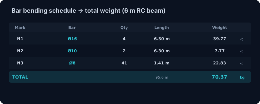
Take the 6 m simply-supported beam we design later in this article: a 250 × 500 mm section in CA-50 steel. Its schedule reads:
- N1 — bottom bars: 4 × Ø16, cut 6.30 m (span plus anchorage into each support). At 1.578 kg/m that is 4 × 6.30 × 1.578 = 39.77 kg.
- N2 — top bars: 2 × Ø10 hanger/anti-crack bars, cut 6.30 m. At 0.617 kg/m: 2 × 6.30 × 0.617 = 7.77 kg.
- N3 — stirrups: Ø8 closed ties at 150 mm spacing, 41 of them, each 1.41 m of bent bar (perimeter of the 250 × 500 cage less cover, plus hooks). At 0.395 kg/m: 41 × 1.41 × 0.395 = 22.83 kg.
Add the marks and the beam needs 70.4 kg of reinforcement — about 95.6 metres of bar in total. Multiply across every beam, column and slab and you have the building's rebar tonnage. Two details separate a schedule that matches the delivery slip from one that doesn't: cut length is not clear span (it includes anchorage, hooks and bends), and stirrup length is developed length (the flattened-out perimeter with its hooks), not the section perimeter. The calculator handles both, and exports the whole schedule to CSV or a branded PDF.
If you're weighing rolled steel sections rather than reinforcement, the same logic drives our profile weight guide and the steel weight calculator — same physics, different catalogue.
Weigh your own bars: the live calculator
You've seen the method by hand; the fastest way to make it yours is to drive it. The full CalcSteel rebar calculator is embedded right here — pick a standard, choose a bar, set the length and quantity, and the unit mass, total weight, bars-per-tonne and the cross-code equivalents update instantly.
It is the complete tool, not a teaser: three standards with all 31 bar sizes, kg/m and lb/ft, a saveable bar schedule you export to CSV or a branded PDF, an area-match substitution engine, and a norm-anchored design check (As,min/As,max and development/lap length per NBR 6118, ACI 318 or EC2). It runs entirely in your browser, free and with no login. If it opens in its own tab, here is the direct link to the rebar weight calculator.
Try reproducing the schedule above — 4 × Ø16 at 6.30 m — and watch the 39.77 kg mark appear, then switch the whole run to ASTM #5 and see the weight and the bar count move together. Everything in the rest of this article is a number you can now generate and interrogate yourself.
Tri-norm equivalence — 10 mm CA-50
Nearest bar by diameter in each standard, with the mass difference vs. your selection — the number a cross-code spec conversion or an import substitution turns on.
W = (kg/m) × L × n = 0.617 kg/m × 12 m × 100 = 740.4 kg
Total weight · 100 bars
740.4 kg
Unit mass
0.617 kg/m
Procurement — 10 mm CA-50
Stock bars assume 1 whole cuts per 12 m bar (no cross-piece nesting) — a conservative first pass for the cut list.
Code check — ABNT NBR 6118
Section OKDevelopment ℓb
377 mm (38φ)
min 113 mm
Lap ℓs · α₀t=1.5 (>50% lapped)
565 mm (57φ)
min 200 mm
fctm=2.565 MPa · fbd=2.886 MPa · fyd=434.8 MPa
Ribbed high-bond bar, "good" bond position, straight anchorage (α=1.0). NBR 6118 §9.3. Preliminary — verify against the governing code.
Substitution — match the steel area
| Use | As deliv. | +% | Δmass | Spacing |
|---|---|---|---|---|
| 2×16 mm | 402 | +2% | +2% | 108 mm |
| 8×8 mm | 402 | +3% | +2% | 11 mm |
| 13×6.3 mm | 406 | +3% | +3% | 5 mm |
| 21×5 mm | 412 | +5% | +5% | 2 mm |
| 4×12.5 mm | 491 | +25% | +25% | 30 mm |
| 1×25 mm | 491 | +25% | +25% | — |
| 2×20 mm | 628 | +60% | +60% | 100 mm |
| 1×32 mm | 804 | +105% | +105% | — |
n = ⌈As,source / area,target⌉ — the substitute always delivers at least the specified steel area. Spacing is the clear gap between bars in a 200 mm section (cover 30 mm); Δmass and Δcost are per metre of the bar group.
Nominal masses per ABNT NBR 7480 (CA-50), ASTM A615/A615M (Grade 60) and EN 10080 / ISO 6935-2 (B500), carbon-steel density 7850 kg/m³. Ribs do not count toward nominal mass — every standard uses the plain-round equivalent section. Design checks (As,min/As,max, ℓb, ℓs) follow NBR 6118 / ACI 318 / EC2 and are preliminary — verify against the governing code. More free tools in the CalcSteel toolbox.
From analysis to rebar: how much steel does a beam need?
Here is where a weight calculator alone runs out of road. The tonnage isn't chosen — it's derived from how hard the member works, and that comes from a structural analysis. The chain is always the same: load → bending moment → required steel area → bar selection → weight. Skip the first two links and you're guessing.
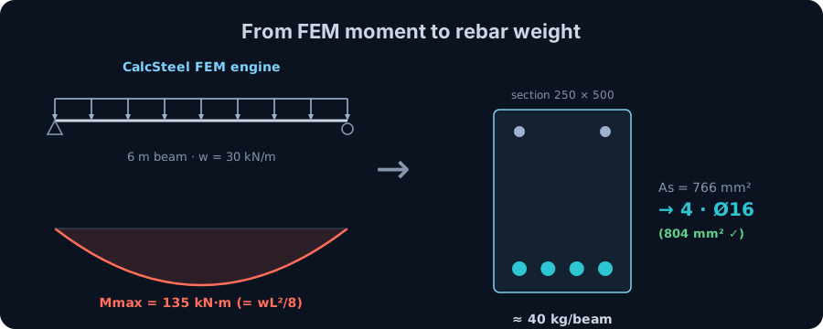
Take a concrete beam of 6 m span, 250 × 500 mm, carrying a factored uniform load of w = 30 kN/m. Modelled in the CalcSteel FEM engine as a rectangular (RET) concrete section, it returns a maximum bending moment of M = 135.0 kN·m at midspan and a shear of 90 kN at the supports — matching the closed form wL²/8 = 30 × 6²/8 = 135 kN·m exactly, as it must for a determinate span. (The internal moment from a linear-elastic analysis depends only on geometry, supports and load, so the FEM value is the honest demand whether the member is steel or concrete.)
Turning the moment into bars
The flexural design then follows the standard simplified lever-arm relation. With an effective depth d ≈ 450 mm, a lever arm z ≈ 0.9d = 405 mm and a design yield of 0.87·fyk = 435 MPa for CA-50:
As = M / (0.87·fyk·z) = 135×10⁶ / (435 × 405) ≈ 766 mm²
Now the catalogue does its job. A Ø16 bar is 201 mm², so you need 766 ÷ 201 = 3.8 → 4 × Ø16, delivering 804 mm² — just above the demand, the mark of an efficient section. At 1.578 kg/m, those four bars over 6.30 m weigh about 40 kg, and with the stirrups and top steel the whole beam is the 70.4 kg from the schedule above. The moment picked the bars; the bars set the weight.
This is the same engine that draws a full shear and bending-moment diagram, solves the support reactions and enforces your load combinations — and it's free in your browser. Change w, the span or the section and the required steel, the bar count and the weight all move with it.
Why analysis matters: the continuous beam
The single span is the easy case, where hand formulas still work. Add one support and the takeoff changes shape entirely — and this is exactly where an analysis engine earns its keep for a rebar estimate.
Make the beam continuous over two 6 m spans under the same w = 30 kN/m. There are now three reactions but only two equations of statics, so the beam is statically indeterminate — its own stiffness decides how the load shares out. The CalcSteel engine solves it directly and returns:
- Hogging over the interior support: −135.0 kN·m (exactly −wL²/8 for this symmetric two-span case). This is negative, so the top fibre is in tension over the support — the reinforcement has to move to the top there.
- Sagging in each span: +75.9 kN·m (= 9wL²/128), well below the support moment.
- Reactions of 67.5, 225 and 67.5 kN — the interior support carries far more than half the load because it is stiff and draws load toward itself.
For the rebar takeoff this has real consequences. The governing steel is now the top bars over the support, sized for 135 kN·m (again ≈ 766 mm² → 4·Ø16, but on the top face), while each span needs only about 431 mm² of bottom steel → 3·Ø16. A weight calculator that assumed a simple beam would have put all the heavy steel in the bottom of the spans and none over the support — the tonnage might be similar, but it would be in the wrong place, and the beam would crack. The moment diagram, not intuition, tells you where the kilograms go. Solving it by hand means moment distribution or the three-moment equation; the engine does it in milliseconds, and it's free.
Legal steel: As,min and As,max
A bar count that carries the moment still has to be legal. Every reinforced-concrete code brackets the steel area between a minimum and a maximum, and a weight that ignores those limits can be both cheaper and non-compliant. The minimum guards against a sudden, brittle failure the instant the concrete cracks (the steel must be able to carry what the uncracked concrete was carrying); the maximum keeps the section from being so congested that the concrete can't be placed or can't fail in a ductile way.
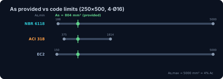
For our 250 × 500 beam with 4·Ø16 (As = 804 mm², a geometric ratio of 0.64 %), the three codes give:
- NBR 6118: As,min = 188 mm² (ρmin = 0.15 % of the gross area), As,max = 5000 mm² (4 % of Ac outside laps).
- ACI 318-19: As,min = 375 mm² (governed by 1.4/fy·b·d), As,max = 1814 mm² (the tension-controlled limit, εt ≥ 0.005).
- EN 1992-1-1 (EC2): As,min = 150 mm² (0.26·fctm/fyk·b·d), As,max = 5000 mm² (4 % of Ac).
Our 804 mm² sits comfortably inside all three — above every minimum, below every maximum. Notice the codes disagree on the numbers (ACI's minimum is the strictest here, and its maximum is far tighter because it caps ductility directly) even though the physics is shared. That is why a serious rebar calculator pins the check to the standard you're actually building to, rather than quoting one global rule of thumb. The calculator's design panel evaluates As,min and As,max for your exact section and flags a bar count that falls outside them.
The hidden kilograms: development and lap length
Here is the weight most quick estimates forget. Bars are rolled in finite stock lengths (typically 12 m), but structures are longer, and a bar can only transfer its force to the concrete over a certain development length ℓb. Where two bars have to be joined, they overlap by a lap (splice) length ℓs, and every lap is steel that carries load only once but is paid for twice. Ignore laps and anchorage and your tonnage will be light — often by 5 to 15 %.
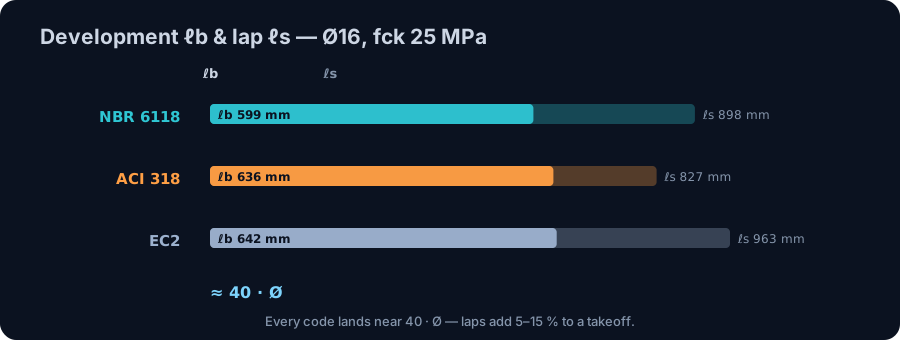
All three codes size the development length from the bond stress between the ribbed bar and the concrete, and they land remarkably close together. For a Ø16 bar in C25 concrete (good bond, straight bar), the calculator computes:
- NBR 6118: ℓb = 599 mm (37.7·Ø), lap ℓs = 898 mm.
- ACI 318: ℓb = 636 mm (40.0·Ø), lap ℓs = 827 mm (Class B, 1.3·ℓd).
- EC2: ℓb = 642 mm (40.4·Ø), lap ℓs = 963 mm.
The rule of thumb that anchorage is "about 40 diameters" is exactly what the physics gives, in every code. Scale it up with the bar: a Ø20 lap runs to roughly 1.1–1.2 m. On a wall or a long slab with bars lapped every 12 m, those extra 0.9–1.2 m per splice are precisely the 5–15 % that separates the theoretical bar weight from the actual delivered weight. A credible rebar takeoff always adds the laps — the calculator reports ℓb and ℓs for your bar and code so you can build them into the cut lengths, not discover them on site.
Swapping bars the right way: match the area, not the count
Procurement and detailing constantly ask a question a plain weight tool can't answer: the drawing says 5·Ø20, but the yard only has Ø16 — how many do I use? The wrong instinct is to match the count (5·Ø16) or eyeball it. The right rule is to match the steel area, because it's the area that carries the tension the moment demanded.
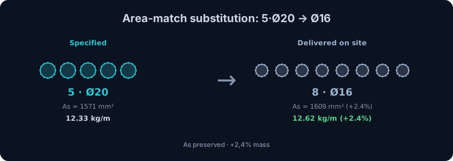
Five Ø20 bars provide As = 5 × 314 = 1571 mm². To replace them with Ø16 (201 mm² each) you need 1571 ÷ 201 = 7.8 → 8 × Ø16, which delivers 1609 mm² — 2.4 % over, never under (you must never under-provide steel). And the weight? The five Ø20 run at 5 × 2.466 = 12.33 kg/m; the eight Ø16 run at 8 × 1.578 = 12.62 kg/m. The substitution costs just +2.4 % in weight for a fully equivalent section — often a worthwhile trade to keep a job moving with the bars actually in stock.
The same area-match logic converts across codes: a European Ø20 finds its nearest ASTM neighbour (#6, 19.1 mm) or its nearest CA-50 size, and the calculator reports how much heavier or lighter the substitute group runs. It also checks that the swap still respects bar spacing — eight Ø16 in a 250 mm-wide beam leave a clear gap of about 25 mm, comfortably above the code minimum, whereas cramming them into a narrower section would not. Substitute by area, verify the spacing, keep the weight honest: that is the procurement move a real rebar calculator automates. The substitution panel ranks every legal swap by weight, lightest first.
Common mistakes & FAQ
The arithmetic is simple, but the same handful of errors quietly wreck rebar estimates. Run through this checklist before you trust any tonnage — hand-computed or from software.
- Confusing theoretical and delivered weight. The nominal (theoretical) mass from the formula is what you design and invoice with. The delivered weight includes laps, anchorage, bends and cutting waste — typically 5–15 % more. Order to the theoretical weight and you'll be short.
- Adding rib weight. The ribs are already excluded by definition; the nominal mass is the plain-round equivalent. Trying to "add back" the deformations double-counts steel that the standard never counted.
- Mixing kg/m and lb/ft. A #4 bar is 0.668 lb/ft or 0.994 kg/m — never both. Fix your units before you multiply, using 1 kg/m = 0.672 lb/ft.
- Substituting by bar count instead of area. Five Ø20 is not five Ø16 — it's eight. Always match As, then round up.
- Forgetting stirrups and secondary steel. In a typical beam the stirrups and top bars can be a third of the weight (22.8 + 7.8 of our 70.4 kg). Bottom bars alone under-count badly.
- Using the wrong moment. On a continuous or fixed member the governing steel is often the hogging top steel over a support, not the span sagging steel. Size it from the real moment diagram.
How do I calculate the weight of a rebar?
Multiply its unit mass by its length and quantity. The unit mass is kg/m = 0.006165·d² with d in millimetres (so Ø16 = 1.578 kg/m), or read it straight from the NBR/ASTM/EN table. For 4 bars of Ø16 at 6.30 m: 4 × 6.30 × 1.578 = 39.8 kg.
How much does a 12 m length of Ø10 rebar weigh?
0.617 kg/m × 12 m = 7.40 kg per bar. A tonne is therefore about 135 such bars, or roughly 1621 metres of Ø10.
Is rebar weight the same in every country?
For the same nominal diameter, yes — a 16 mm bar is 1.578 kg/m under NBR, ASTM (as #5, 15.9 mm ≈ 1.55 kg/m) or EN, because the nominal mass is defined from the diameter. What differs is the preferred sizes and the labels (Ø16 vs #5), not the physics.
How much rebar is in a cubic metre of concrete?
It depends entirely on the element: lightly-loaded slabs might carry 60–90 kg/m³, beams and columns 100–200 kg/m³, and heavily-loaded transfer members more. There is no universal figure — you get it by designing the steel from the moments, exactly as we did above, then dividing by the concrete volume.
Do the ribs (deformations) add to the weight?
No. Every standard defines the nominal mass from the plain round bar of the same nominal diameter, so the ribs are already accounted for in the nominal figure and are never added separately.
Key takeaways
You've gone from a single formula to a fully-designed, code-checked beam and its exact rebar weight. Here's what to carry away.
- One formula rules them all. kg/m = 0.006165·d² — the plain-round equivalent — reproduces every rebar table in every code, and the weight grows with the square of the diameter.
- Three standards, one physics. NBR 7480, ASTM A615 and EN 10080 differ in labels and preferred sizes; the masses coincide wherever the diameters do, and 1 kg/m always equals 0.672 lb/ft.
- A schedule is just a sum. Total weight = unit mass × length × quantity, added over every mark — bottom bars, top bars and stirrups. Our 6 m beam came to 70.4 kg.
- The moment sets the steel. Analysis first: the CalcSteel FEM engine found 135 kN·m, which needed 766 mm² → 4·Ø16 — and on a continuous beam the heavy steel moves to the top over the support.
- Don't lose the hidden kilograms. Laps and anchorage (≈ 40·Ø) add 5–15 %, As,min/As,max keep the steel legal, and cross-code swaps must match the area, not the count.
Now stop reading and start weighing. Put your own bars, lengths and quantities into the free rebar weight calculator — three codes, a full schedule, the design check and CSV/PDF export, with no login. And when you need the moment that decides the steel, CalcSteel runs the same real FEM engine on complete beams and frames right in your browser, on a genuinely free plan. Students get everything unlocked through CalcSteel Education, free. The proof isn't a countdown — it's the tool itself, in your hands today.
Sources
Try CalcSteel for free
Model, analyze and design steel structures in your browser. No install, no signup.
Open the 3D editor