Moment vs Shear Connections: When to Use Each

Understand the difference between moment and shear connections in steel frames. Covers simple, PR, and FR connections, their effect on frame behavior, and design considerations.
What is the difference between a moment connection and a shear connection?
The fundamental difference is what forces the connection transfers:
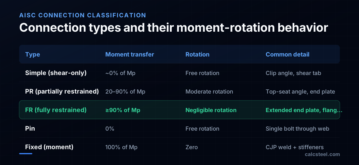
- A shear connection (simple connection) transfers only vertical shear from the beam to the column. The beam end is free to rotate — the connection behaves like a pin. The beam is designed as simply supported.
- A moment connection (rigid connection) transfers both shear AND bending moment. The beam end cannot rotate freely — the beam and column act as a continuous frame. The beam gets negative moments at the ends, which reduces the midspan moment.
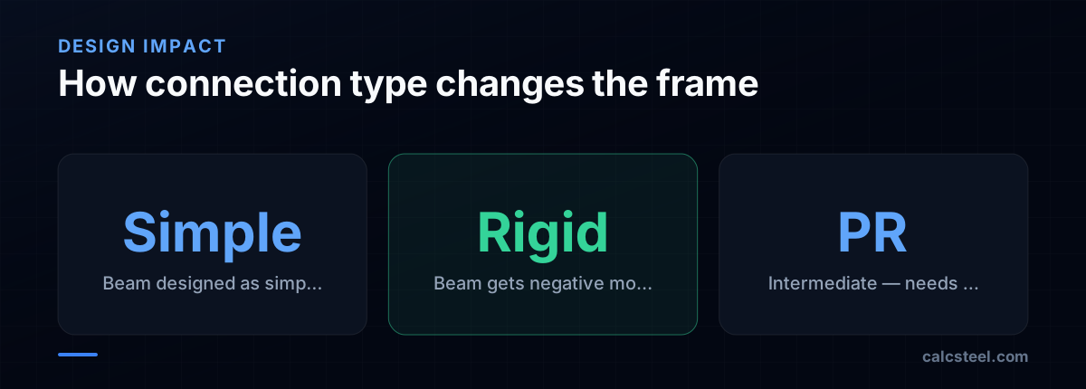
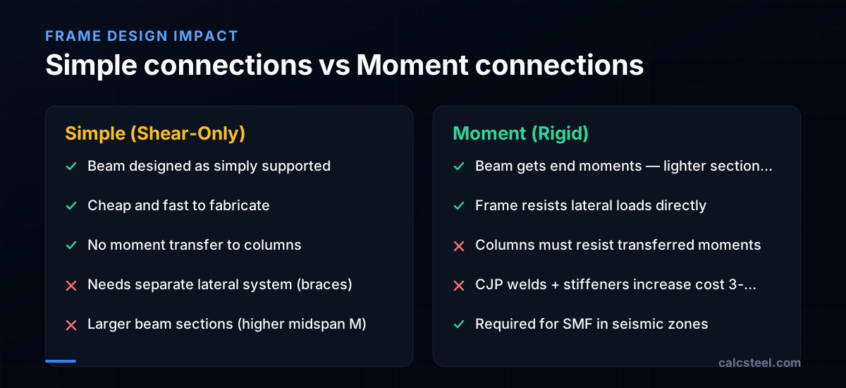
This distinction is not just a connection detail — it fundamentally changes how the entire frame behaves: - With simple connections, you need a separate lateral system (braces or shear walls) - With moment connections, the frame itself resists lateral loads - The beam size, column size, foundation design, and cost all change depending on the connection type
AISC classifies connections by their moment-rotation (M-θ) behavior: - FR (Fully Restrained): Transmits ≥ 90% of the connected beam's plastic moment with negligible rotation. This is the "rigid" connection. - PR (Partially Restrained): Transmits between 20–90% of the beam's moment with measurable rotation. - Simple: Transmits negligible moment with free rotation.
What types of shear connections are used in steel structures?
Shear connections are the most common connection type — roughly 70% of beam-to-column connections in a typical building are simple shear connections.
Single-plate connection (shear tab) A plate welded to the column flange and bolted to the beam web. The simplest and most popular shear connection in the US. - Advantages: easy to fabricate, easy to erect, minimal material - Capacity: up to about 500 kN for deep beams - Limitation: the plate must be thin enough to allow rotation
Double-angle connection (clip angles) Two angles bolted to the beam web and to the column flange (or web). The outstanding legs flex to allow beam rotation. - Advantages: robust, easy to inspect, good ductility - Capacity: higher than shear tabs for heavy beams - Limitation: more bolts and material than shear tabs
Seated connection (seat angle) An angle or tee welded or bolted under the beam's bottom flange, providing a "seat" for the beam to rest on during erection. - Advantages: easy erection (beam sits on the seat) - Capacity: limited by the angle leg bending - Often combined with a top clip angle for stability
End plate (flexible) A thin end plate welded to the beam end and bolted to the column. The plate is thin enough to flex, allowing rotation. - Common in the UK and Europe (flush end plate) - Provides both shear transfer and erection stability
What types of moment connections are used in steel frames?
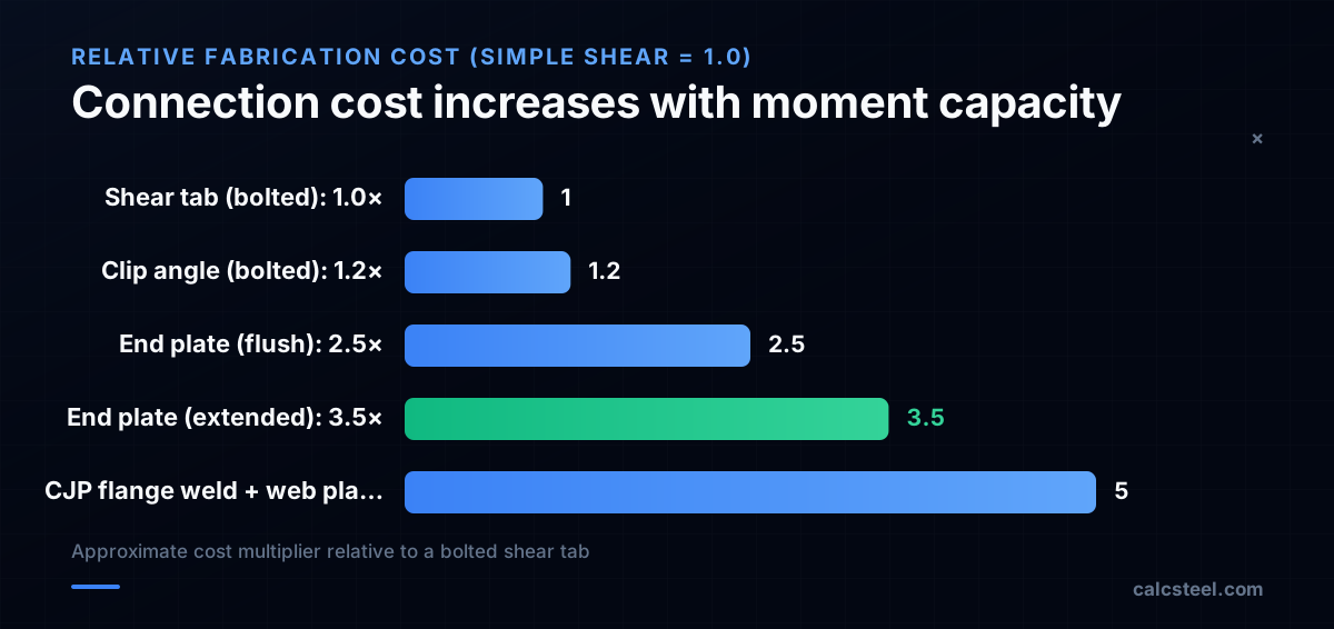
Moment connections must be stiff enough and strong enough to transfer the beam's full (or partial) moment to the column. They are more complex and expensive than shear connections.
Extended end plate A thick end plate welded to the beam end and bolted to the column flange with high-strength bolts. The bolts above and below the beam flanges resist the moment couple. - Advantages: shop-welded, field-bolted (fast erection) - Capacity: depends on bolt size, number, and plate thickness - Common in portal frames and moderate moment frames
Directly welded flange connection Beam flanges are welded directly to the column flange with complete joint penetration (CJP) welds. The beam web is connected with a shear tab or bolted plate. - Advantages: highest stiffness, develops full beam moment - Disadvantages: field welding is expensive, requires UT inspection - Required for Special Moment Frames (SMF) in seismic design
Bolted flange plate connection Plates are welded to the column and bolted to the beam flanges, plus a web plate for shear. - Advantages: all-bolted field connection (no field welding) - Capacity: limited by bolt bearing on the flange - Popular for wind moment frames
Reduced Beam Section (RBS / "dogbone") The beam flanges are trimmed near the connection to force the plastic hinge to form in the beam, away from the weld. This protects the brittle CJP weld from fracture. - Required for post-Northridge seismic design in high-seismic regions - Reduces the moment demand on the connection by ~30%
How does connection type affect beam and column design?
The connection type determines the moment diagram in the beam and column, which drives the member sizing:
Simple connection (pin) - Beam moment diagram: parabolic, maximum at midspan = wL²/8 - Column moment: zero from the beam (column designed for axial + eccentricity only) - Beam is heavier (full midspan moment) - Column is lighter (no transferred moment) - Need separate bracing system
Moment connection (rigid) - Beam moment diagram: negative moments at ends, reduced positive moment at midspan - For uniform load: end moment ≈ wL²/12, midspan moment ≈ wL²/24 - Column moment: must resist the transferred end moment - Beam is lighter (midspan moment reduced by 67%) - Column is heavier (must carry transferred moment) - Frame resists lateral loads directly
Example comparison — 9 m beam, w = 30 kN/m
| Item | Simple | Moment |
|---|---|---|
| Max beam moment | wL²/8 = 304 kN·m | wL²/24 = 101 kN·m |
| Required Z_x | 979 cm³ | 326 cm³ |
| Typical beam | W460×74 | W360×39 |
| Beam weight saved | — | 35 kg/m (47%) |
| Column receives | 0 kN·m | 304 kN·m (end moment) |
| Extra column cost | None | Heavier column + stiffeners |
The beam weight savings are significant, but the total structural cost includes the heavier column and expensive moment connection. For most buildings, simple connections with bracing are more economical.
When should you use moment connections vs shear connections?
The choice depends on several factors beyond just structural efficiency:
Use simple (shear) connections when: - Cost is the priority — Simple connections are 2–5× cheaper to fabricate and erect - A separate lateral system exists — Braced frames or shear walls handle the lateral loads - The spans are short to moderate (< 12 m) — The beam weight penalty is small - Erection speed matters — Bolted shear connections are the fastest to erect
Use moment connections when: - Open floor plan is required — No diagonal braces allowed - Seismic design requires ductility — Special Moment Frames provide the highest R factor - Wind is the dominant lateral load — The frame must resist wind without braces - Reduced beam depth is needed — End moments reduce the required beam depth - Cantilever continuity is needed — The beam extends past the column as a cantilever
Hybrid approach (most common in practice)
Most buildings use a combination: - Core braced frames for primary lateral resistance (stiff and cheap) - Gravity frames with simple connections for all non-lateral beams (fast and cheap) - Perimeter moment frames only where architectural openness is needed
This hybrid approach minimizes the number of expensive moment connections while providing architectural flexibility where it matters.
What is a partially restrained connection and when is it used?
A partially restrained (PR) connection falls between simple and rigid. It transfers some moment but also allows some rotation. The connection has a characteristic moment-rotation (M-θ) curve that defines its stiffness and strength.
Common PR connection types
- Top-and-seat angle: Angles bolted to both flanges plus a web angle for shear. The angle leg flexes, providing partial fixity.
- Header plate (partial depth end plate): An end plate that extends only partway up the beam depth.
- Flush end plate with standard bolts: Not thick enough to be fully rigid but stiffer than a simple connection.
Design implications
- Analysis must use the M-θ curve — You cannot assume simple or rigid behavior. The frame analysis must model the connection as a nonlinear spring with the actual stiffness.
- Beam moments are between simple and rigid values — Midspan moment is less than wL²/8 but more than wL²/24.
- Columns receive some moment — Less than with rigid connections but more than zero.
- Iterative design — The connection stiffness affects the frame forces, which affect the connection design, creating an iterative loop.
When PR connections make sense
- In low-rise frames where full rigidity is not needed but some moment transfer reduces beam size
- In existing structures where adding fully rigid connections is impractical
- In European practice where flush end plates are standard
In US practice, PR connections are less common because the analysis complexity is not justified for most buildings. Designers prefer the clarity of either simple or rigid.
What are seismic requirements for moment connections?
The 1994 Northridge earthquake exposed critical failures in pre-Northridge welded moment connections. Brittle fractures occurred at the beam-flange-to-column-flange CJP welds, causing connection failures without warning.
Post-Northridge seismic design (AISC 341, AISC 358) requires:
Prequalified connections AISC 358 provides prequalified moment connection details that have been tested and shown to achieve the required rotation capacity: - Reduced Beam Section (RBS): Flanges trimmed to force the plastic hinge away from the weld - Bolted Unstiffened Extended End Plate (BUEEP): Thick end plate with high-strength bolts - Welded Unreinforced Flange-Welded Web (WUF-W): Direct flange welds with improved welding procedures
Rotation capacity requirements
| Frame type | Required rotation | Typical connection |
|---|---|---|
| SMF (Special) | 0.04 rad | RBS, WUF-W |
| IMF (Intermediate) | 0.02 rad | Extended end plate |
| OMF (Ordinary) | 0.01 rad | Standard end plate |
Key detailing requirements
- Demand-critical welds — CJP welds at beam flanges must use high-toughness filler metal (AWS A5.20 E71T with CVN ≥ 27J at −29°C)
- Continuity plates — Column stiffeners aligned with beam flanges to prevent column flange bending
- Panel zone check — Column web panel zone must be checked for shear and may require doubler plates
- Strong-column / weak-beam — ΣM_pc ≥ ΣM_pb ensures plastic hinges form in beams, not columns
- Weld access holes — Must comply with AWS D1.8 for seismic applications
How does CalcSteel design connections?
CalcSteel's connection engine designs both shear and moment connections based on the demand forces from the analysis:
Automatic connection type selection Based on the member end releases in the model: - Pinned ends → shear connection (auto-selects shear tab, clip angle, or end plate based on demand) - Fixed ends → moment connection (auto-selects extended end plate or welded flange based on demand)
Connection design checks
For shear connections: - Bolt shear, bearing, tearout - Block shear on the plate and beam web - Weld capacity (if shop-welded) - Plate thickness for flexural yielding (to allow rotation)
For moment connections: - Bolt tension and shear (combined interaction) - End plate bending (yield line analysis) - Column flange bending - Column web panel zone shear - Continuity plate (stiffener) requirements - Weld capacity for CJP and fillet welds
Connection detail output Each connection exports as a detailed drawing with: - All dimensions, bolt sizes, and weld callouts - Force summary and utilization ratios - Material specifications - DXF export for direct use in shop drawings
The engineer can override the auto-design at any time, and all checks update instantly for the new configuration.
Try CalcSteel for free
Model, analyze and design steel structures in your browser. No install, no signup.
Open the 3D editor