Mohr's Circle: Stress States from Element to FEM
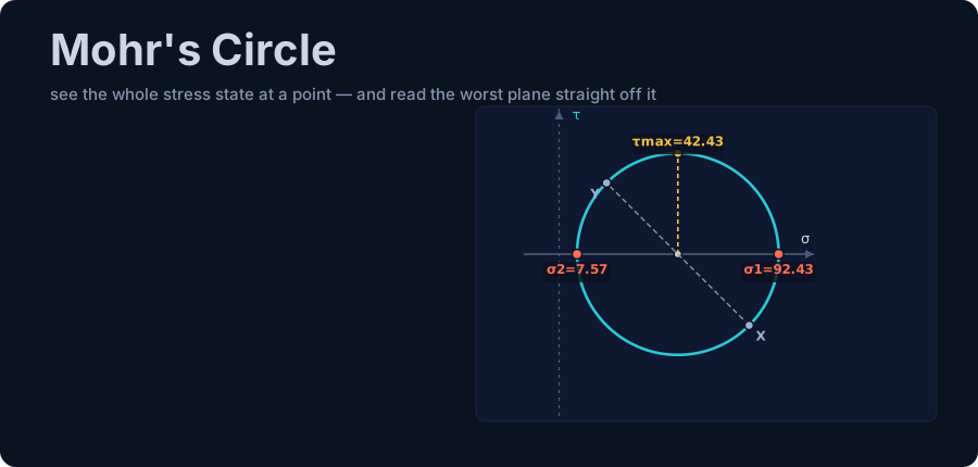
Master Mohr's circle: read principal stresses, von Mises and max shear from a 2-D stress state, then check a real FEM steel fibre — free calculator.
Key takeaways
- A point in a loaded body feels a full 2-D stress state, and every plane through it maps to one point on a single circle centred at σavg with radius R = τmax.
- The circle hands you the design numbers directly: the σ-axis crossings are the principal stresses σ1 and σ2, the crown is τmax = R, and σ1 + σ2 = σx + σy is invariant at every angle.
- Angles double on the circle — a physical rotation θ sweeps 2θ — so the maximum-shear plane always sits 45° from the principal plane, and the out-of-plane σ3 = 0 circle sets the true τabs,max.
- One cross-section gives different circles at different fibres: an IPE 330 beam-column is uniaxial compression at the extreme fibre but a genuine combined state at the neutral axis, so a correct check inspects both.
- The circle ends in a code check: its principal stresses feed von Mises σvM = √(σ1² − σ1σ2 + σ2²), and η = σvM / f_yd — 0.842 to NBR 8800, 0.850 to AISC 360 for the real portal frame's governing fibre.
From a stress element to a real FEM member fibre
Push a steel beam and something happens inside it that your intuition quietly gets wrong. A fibre near the flange, the metal around a bolt hole, the throat of a weld, a slice of web carrying bending and shear at once — none of them feels a single "up-or-down" stress. Each one sits in a full two-dimensional stress state that changes depending on the angle of the plane you choose to look at. Turn the plane and the normal stress rises while the shear falls; turn it further and the shear vanishes entirely. The material does not care about your coordinate axes — it fails on whichever plane is working hardest, and that plane is almost never the one you drew first.
Mohr's circle is the 140-year-old picture that lets an engineer see that state and read the worst plane straight off it. Plot normal stress on one axis and shear on the other, and every plane through a point collapses onto a single circle. The two places where it crosses the horizontal axis are the principal stresses σ1 and σ2 — the planes with zero shear — and the radius is the maximum shear the point will ever feel. One drawing answers the whole question of "which direction is dangerous."
This is meant to be the definitive walkthrough, and it goes the whole distance: from the σx/σy/τxy definition of a stress element, through a hand-drawn circle in five steps, all the way to a real FEM member fibre and the code check that decides whether it passes. Every worked number here was produced by the CalcSteel finite-element engine — the same solver that ships in the app — and cross-checked against closed-form algebra to three decimals. There is a live, draggable Mohr's circle embedded further down the page so you can reproduce each result yourself.
We wrote it for three readers at once. If you are a student, treat it as the stress-transformation chapter your course races through in a single lecture. If you are a practising engineer, jump to the FEM hand-off and the real steel building, where the circle stops being a textbook toy and starts painting the verification colours on a 3-D model. And if you are simply curious how software knows a member is safe, follow the story — it ends inside a working portal frame.
The CalcSteel Mohr's circle calculator is free, runs in your browser with no login for the math, and draws every circle in this article as you read it.
What Mohr's circle actually is
Mohr's circle is a graphical form of the two-dimensional stress-transformation equations: plot normal stress σ on the horizontal axis and shear stress τ on the vertical axis, and every plane through a point maps to exactly one point on a single circle. Where the circle crosses the σ-axis — where the shear is zero — are the principal stresses, and its radius is the maximum in-plane shear.
That is the whole idea in one paragraph. The state of stress at a point is not one number; it is three — σx, σy and τxy — and those three completely determine what happens on every other plane through that point. The transformation equations tell you the normal and shear stress on a plane rotated by any angle θ. Mohr's insight was that if you feed those equations onto a σ-versus-τ chart, the locus of all possible planes is not some messy curve — it is a perfect circle, centred on the σ-axis at the average of σx and σy.
Once you have the circle, you have the answers by inspection. The two horizontal-axis crossings are the principal stresses σ1 (the largest normal stress at the point) and σ2 (the smallest), and on those two planes the shear is exactly zero. The top and bottom of the circle give the maximum in-plane shear τmax, equal to the radius. The centre never moves as you rotate, because the sum σx + σy is an invariant — a fact we will lean on hard as a self-check.
The single most important thing to carry into the next section is the angle relationship. Physically rotating the inspection plane by an angle θ sweeps you twice as far — a full 2θ — around Mohr's circle. Rotate the real plane by 45° and you travel 90° around the circle, which is exactly why the plane of maximum shear sits 45° from the plane of maximum normal stress. Master that one doubling and the rest of the picture reads itself.
Where the circle came from
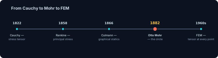
Mohr's circle feels timeless, but almost every idea inside it has a date and a name. It took the better part of a century to get from the first rigorous definition of stress on a plane to the elegant circle engineers now sketch from memory — and only a few decades more before a solver could build that circle at every fibre of a structure automatically.
- 1822 — Augustin-Louis Cauchy puts stress on a firm mathematical footing, introducing the stress tensor and the traction (force per area) acting on an arbitrary plane through a point. Everything that follows is a way of visualising Cauchy's tensor.
- 1858 — William Rankine names and formalises principal stress — the planes on which shear vanishes and the normal stress is extreme — giving the two σ-axis crossings their meaning.
- 1866 — Karl Culmann, working in graphical statics, draws the first stress circle: a geometric construction for transforming stress, and the direct ancestor of the diagram we use today.
- 1882 — Otto Mohr generalises Culmann's construction into the complete circle that now carries his name, showing how to read every plane, both principal stresses and the maximum shear from one drawing — and arguing that it is the shear stress that governs the failure of ductile materials.
- ~1900 — August Föppl and others popularise the method in the great German engineering textbooks, and it becomes standard fare in strength-of-materials teaching worldwide.
- 1950s–60s — matrix structural analysis and the finite element method turn stress analysis into linear algebra a computer can execute, evaluating Cauchy's tensor at every point of a mesh without a single hand construction.
Today that whole lineage runs the instant you press a button. A modern solver computes the stress tensor at every fibre and builds the corresponding Mohr's circle in milliseconds — the same construction Mohr drew by hand in 1882, reproduced thousands of times over before you finish reading this sentence. When the CalcSteel calculator draws a circle, it is compressing a century of mechanics into a few milliseconds, and it is free.
The stress element & sign convention
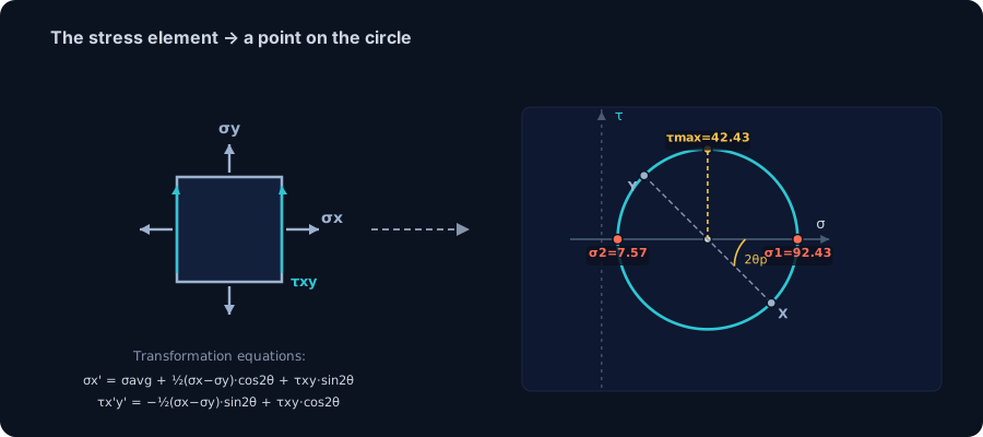
Everything starts with a tiny square cut from the loaded body — the stress element. Imagine zooming in on a single point until the material around it looks like a little square (in three dimensions, a cube) aligned with your x and y axes. On its two vertical faces acts the normal stress σx; on its two horizontal faces, σy; and along its edges, the shear stress τxy. Those three numbers are the 2-D state of stress at that point. Choose any other orientation and the same physical state shows up as different σ and τ values — which is exactly what the circle organises.
Before drawing anything, fix a sign convention and never let go of it. Throughout this guide:
- Tension is positive, compression is negative for normal stress σ. A fibre being pulled apart reads to the right on the circle; a fibre being crushed reads to the left.
- Shear is plotted so a physical counter-clockwise rotation of the plane becomes a counter-clockwise sweep on the circle. Concretely, we plot the X face at the point (σx, −τxy) and the Y face at (σy, +τxy). Those two points are always diametrically opposite — they are the ends of a diameter — and the line joining them passes through the centre.
Which convention you choose matters far less than using it consistently from the first point to the last. Pick this one, keep it, and the angle you read off the circle will always turn the same way as the plane you are rotating in the real element.
The circle is just a picture of the stress-transformation equations. For a plane rotated by an angle θ from the x-axis, the normal and shear stresses are:
- σx'(θ) = (σx + σy)/2 + (σx − σy)/2 · cos 2θ + τxy · sin 2θ
- σy'(θ) = (σx + σy)/2 − (σx − σy)/2 · cos 2θ − τxy · sin 2θ
- τx'y'(θ) = −(σx − σy)/2 · sin 2θ + τxy · cos 2θ
Notice the 2θ everywhere: this is the algebra behind the "real angle θ, circle angle 2θ" doubling from the last section. The first equation is the horizontal coordinate of a point moving around a circle of centre (σx + σy)/2; the third is its vertical coordinate. That is all Mohr's circle is — those two equations, drawn.
Here is the canonical five-step recipe to build the circle from any (σx, σy, τxy):
- Find the centre. It sits on the σ-axis at the average σavg = (σx + σy)/2 — no shear, because the centre is where the two normal-stress contributions balance.
- Find the radius. R = √[ ((σx − σy)/2)² + τxy² ]. This is the maximum in-plane shear the point can feel.
- Plot the two face points. X = (σx, −τxy) and Y = (σy, +τxy); the line through them is a diameter and confirms your centre and radius.
- Read the principal stresses. σ1 = σavg + R and σ2 = σavg − R, the two crossings of the σ-axis, where τ = 0. The principal-plane angle is θp = ½·atan2(2τxy, σx − σy), measured to σ1.
- Read the maximum shear. τmax = R, at the top and bottom of the circle, on a plane 45° from the principal plane (θs = θp − 45°).
Every worked example that follows uses exactly these five steps — and so does the calculator, just faster. If you want to see where the σ and τ that feed step 1 come from in a real member, the companion combined axial and bending and bending moment primers trace the internal forces back to the section.
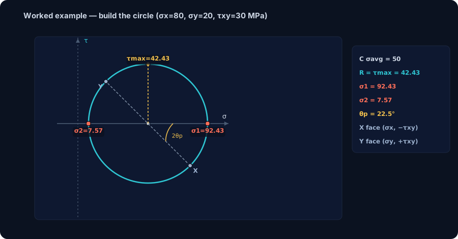
Worked example: build the circle in 5 steps
Theory sticks the moment you draw one. Let's take the same general plane-stress state you'll meet in the live calculator a section from now and build its Mohr circle by hand, step by step. The inputs are the canonical case: σx = 80 MPa (tension), σy = 20 MPa (tension) and τxy = 30 MPa. This is exactly the calculator's default preset, so when you reach the embed you can reproduce every number below without typing a thing.
Step 1 — Plot the two face points
Using the plotting convention from the previous section, the X face goes at (σx, −τxy) = (80, −30) and the Y face at (σy, +τxy) = (20, +30). Those two points are diametrically opposite on the circle — draw the line between them and you already have the diameter.
Step 2 — Find the centre
The centre always sits on the σ-axis at the average normal stress:
- σavg = (σx + σy) / 2 = (80 + 20) / 2 = 50 MPa.
So the centre is C = (50, 0). Notice the shear coordinate of the centre is always zero — that's what makes the principal axis the σ-axis.
Step 3 — Find the radius
The radius is the distance from the centre to either face point. Horizontally that distance is (σx − σy)/2 = 30 MPa; vertically it is τxy = 30 MPa. So:
- R = √[((σx − σy)/2)² + τxy²] = √(30² + 30²) = √1800 = 42.43 MPa.
Step 4 — Read the principal stresses
The principal stresses are where the circle crosses the σ-axis — the centre plus or minus the radius:
- σ1 = σavg + R = 50 + 42.43 = 92.43 MPa,
- σ2 = σavg − R = 50 − 42.43 = 7.57 MPa.
The maximum in-plane shear is simply the radius, τmax = R = 42.43 MPa, sitting at the very top and bottom of the circle.
Step 5 — Find the angle to the principal plane
The angle from the X face round to σ1 — measured on the circle, so it's double the physical rotation — comes straight from the geometry:
- θp = ½ · atan2(2τxy, σx − σy) = ½ · atan2(60, 60) = ½ · 45° = 22.5°.
So rotating the physical element by 22.5° lands you on the principal plane where the shear vanishes and σ1 = 92.43 MPa acts alone. A quick sanity check that never fails: σ1 + σ2 = 92.43 + 7.57 = 100 MPa = σx + σy — the sum of normal stresses is invariant at every rotation angle, so if it doesn't add up, a number is wrong.
Five steps, one circle, and every quantity a design check needs is now readable off the drawing. In the next section we'll walk the circle itself and see exactly where each of these values lives — and in the section after that you can rebuild this whole picture live in the CalcSteel Mohr's circle calculator.
Reading the circle: σ1, σ2, τmax and the angles
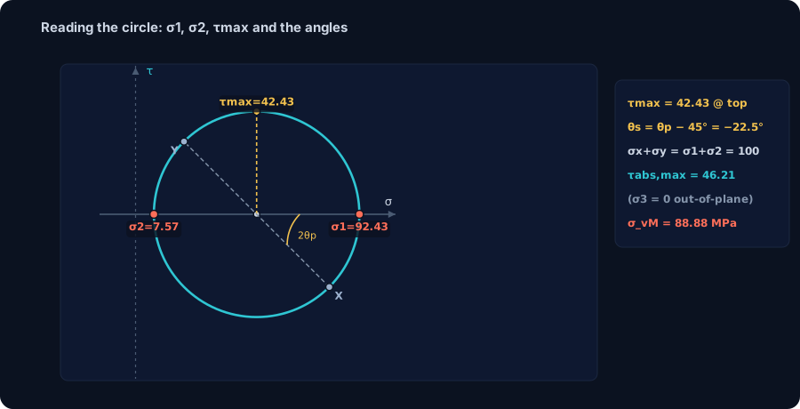
Once the circle is drawn, it becomes a dashboard — every quantity a stress check needs has a fixed home on it. Keep the worked state in mind (σx = 80, σy = 20, τxy = 30 MPa, centre 50, radius 42.43) and let's tour the geometry.
The two σ-axis crossings are the principal stresses
Where the circle cuts the horizontal axis, the shear coordinate is zero — no shear on that plane — so those crossings are by definition the principal stresses. The right-hand crossing is σ1 = 92.43 MPa, the left-hand one is σ2 = 7.57 MPa. Physically, σ1 is the largest tension any plane through the point feels, and it acts on a face rotated θp = 22.5° from the original X face.
The top and bottom are the maximum in-plane shear
The highest and lowest points of the circle sit a full radius above and below the axis, so the maximum in-plane shear equals the radius, τmax = R = 42.43 MPa. Because a diameter subtends 180° on the circle and 180° on the circle is 90° in the real element, the top of the circle is 90° of arc from the principal crossing — a physical 45°. That is the rule worth burning in: the plane of maximum shear is always 45° from the principal plane, here at θs = θp − 45° = −22.5°. On that plane the shear is at its peak and the normal stress is exactly σavg = 50 MPa.
The invariant that checks your work
Spin the element to any angle and the two normal-stress readings still sum to the same number: σx' + σy' = σx + σy = σ1 + σ2 = 100 MPa. Geometrically that's obvious — the two points stay diametrically opposite, so their σ-coordinates always average to the centre. It's the fastest self-check there is.
The out-of-plane circle you must not forget
Plane stress isn't truly two-dimensional — the third principal stress is σ3 = 0, out of the plane. Draw the circle between σ1 = 92.43 and that σ3 = 0 and its radius is larger than the in-plane one. The absolute maximum shear is therefore τabs,max = σ1/2 = 46.21 MPa, not the 42.43 MPa in-plane value. This bigger number — not the in-plane τmax — is what a Tresca check actually uses, and it's the single most common thing engineers miss when they treat a plane-stress problem as if the third circle didn't exist.
So from one drawing you read the worst tension (σ1), the worst compression (σ2), the worst in-plane shear (R), the worst shear of all (τabs,max), and the angles to each. That's the whole point of the circle — and next you'll do it yourself with a draggable version.
Draw your own: the live calculator
You've built the circle by hand and toured every landmark on it. The fastest way to make it permanent is to grab it and move it — so here it is, live and embedded right on this page.
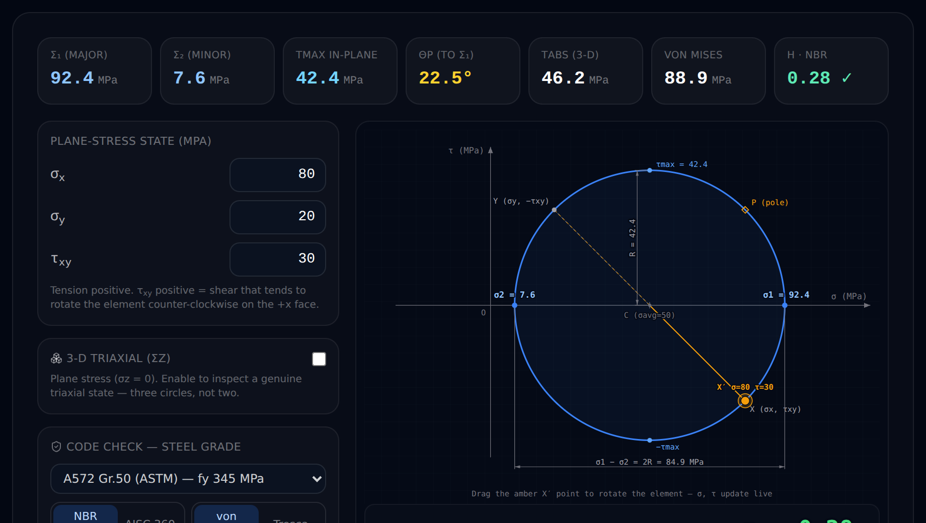
Load the worked state — σx = 80, σy = 20, τxy = 30 MPa (it's the default, so it may already be there) — and confirm the numbers you just derived: centre 50, radius 42.43, σ1 = 92.43, σ2 = 7.57, θp = 22.5°. Then start dragging. Push τxy up and watch the circle swell, σ1 and σ2 spread apart, and θp rotate toward 45°; pull it to zero and the circle collapses onto the axis until σx and σy are the principal stresses. Rotating the plane sweeps twice as far around the circle — you can watch the 2θ relationship happen in real time.
It's the real tool, not a teaser: unlimited runs, completely free, and no login required for the math. When you're ready to go further you can load a real solved FEM section, switch from plane stress to a full 3-D triaxial state with all three circles, and share a permalink to the exact state you're looking at. If it opens in its own tab, here's the direct link to the CalcSteel Mohr's circle calculator.
Play with the textbook state here, because in the sections that follow the stresses stop coming from tidy inputs and start coming from a real member — a beam-column and then a full steel building — where the finite-element engine hands the circle its σ and τ automatically. If you want to see where those internal forces come from first, the companion guide on shear force and bending moment diagrams is the perfect warm-up.
σ₁ (major)
92.4MPa
σ₂ (minor)
7.6MPa
τmax in-plane
42.4MPa
θp (to σ₁)
22.5°
τabs (3-D)
46.2MPa
von Mises
88.9MPa
η · NBR
0.28 ✓
Plane-stress state (MPa)
Tension positive. τxy positive = shear that tends to rotate the element counter-clockwise on the +x face.
Plane stress (σz = 0). Enable to inspect a genuine triaxial state — three circles, not two.
Code check — steel grade
σvM = 88.9 MPa ≤ 313.6 MPa = fy / γa1 (γa1 = 1.10)
NBR 8800:2008 §5.4.2.2 (γa1 = 1,10)
From your solved model
Solve a model in the CalcSteel 3D editor, then return here to load the real σx/σy/τxy at any member section — Mohr's circle becomes the solver's inspection lens.
Presets
Element rotation θ
0°Export (free · no watermark)
Special stress states you'll recognise on sight
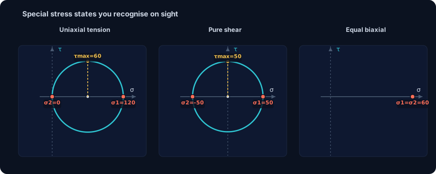
Once you have drawn a few circles by hand, a handful of stress states start to look like old friends. Their circles have such distinctive shapes that you can read the answer before you finish the arithmetic. Memorise these three and you will sanity-check almost any real result in seconds.
Uniaxial tension (or compression)
Pull a bar straight along its axis and only one normal stress survives: σx = σ, σy = 0, τxy = 0. The circle is centred at σ/2 with radius σ/2, so it passes cleanly through the origin. The two σ-axis crossings are the principal stresses: σ1 = σ and σ2 = 0. The top of the circle sits at τmax = σ/2, on a plane 45° to the bar axis — which is exactly why a ductile tensile coupon necks and shears along 45° slip planes, and why a brittle chalk stick in tension breaks square. This is not just a textbook toy: the extreme bending fibre of a real member is a uniaxial state, and you will meet it again as a genuine FEM result in the next section.
Pure shear
Now load a bolt group or a beam web so there is only shear: σx = σy = 0, τxy = τ. The centre lands at the origin and the radius is τ, so the circle is centred on zero and symmetric. The principal stresses come out equal and opposite: σ1 = +τ and σ2 = −τ. In other words, a state of pure shear is also a state of equal tension and compression rotated 45° away. That 45° is the reason a shaft in torsion made of brittle material fractures along a helical 45° surface rather than straight across — the tension diagonal, not the shear itself, is what tears it.
Equal biaxial and hydrostatic states
Finally, load a point equally in both directions: σx = σy = σ, τxy = 0. The radius R = √[((σ − σ)/2)² + 0²] is exactly zero, so the circle collapses to a single point on the σ-axis. A point-circle carries a blunt message: there is no shear stress on any plane whatsoever, and every direction is a principal direction. A thin spherical pressure-vessel wall approaches this equal-biaxial state; a truly hydrostatic (equal in all three directions) state is what a fluid feels, and it produces zero distortion — the fact that underlies the whole von Mises criterion we reach shortly.
These three silhouettes — a circle through the origin, a circle straddling the origin, and a circle shrunk to a dot — are the vocabulary of everything that follows. Load any of them into the free Mohr's circle calculator and watch the shape snap into place before you trust a single number.
From the FEM solver to a fibre: a real member
Textbook circles start with σx, σy and τxy already handed to you. Real design never does. A finite-element solver gives you internal forces at a section — an axial force N, a shear V and a bending moment M — and it is up to you (or the engine) to turn those into the stresses that build the circle. The bridge is elementary mechanics of materials:
- Normal stress from axial plus bending: σ = N/A ± M/Sx, largest at the extreme fibre furthest from the neutral axis.
- Shear stress from the transverse force: τ ≈ V/Aw, largest at the neutral axis where bending stress vanishes.
The sign twist is the whole point: the two stresses peak in different places. So a single cross-section does not have one Mohr's circle — it has a different circle at every fibre, and the two that matter sit at opposite ends of the web.
The member: an IPE 330 beam-column
Take a 3 m cantilever in IPE 330 (area A = 62.6 cm², elastic modulus Sx = 685.9 cm³, web shear area Aw = 24.75 cm²), grade S355. Load the free tip with an axial Fx = −150 kN (compression) and a transverse Fy = 20 kN. Running it through the shipping CalcSteel FEM engine (the same run_analysis that drives the 3-D editor), the fixed base returns N = −150 kN, V = 20 kN, M = 60 kN·m. Now inspect two fibres of that one section.
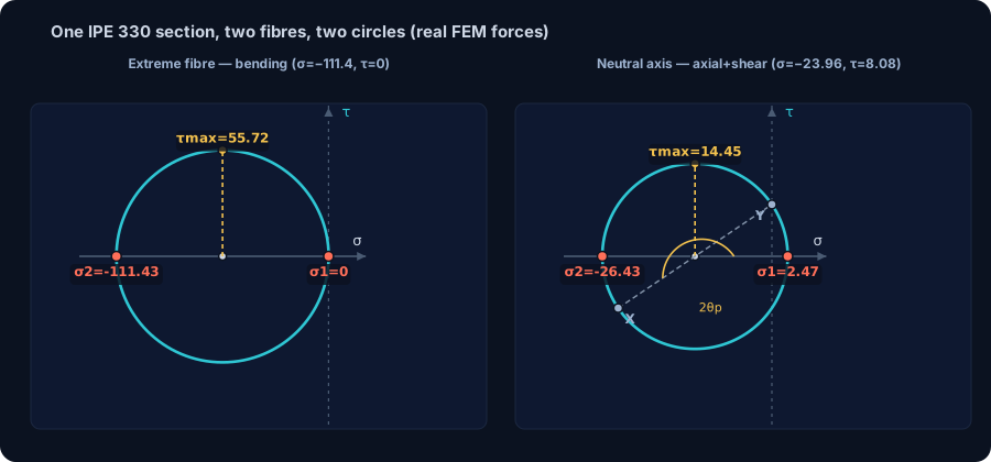
Fibre 1 — the extreme fibre (bending governs, τ = 0)
At the outermost fibre the bending stress is maximal and the transverse shear is zero. Stacking axial and bending: σx = N/A − M/Sx = (−150/62.6 − 6000/685.9) × 10 = −111.4 MPa, with τ = 0. That is a uniaxial state, so the circle is the special case from the previous section — it passes through the origin: σ1 = 0, σ2 = −111.4 MPa, τmax = 55.7 MPa, principal angle θp = 90°, and von Mises σvM = 111.4 MPa (utilisation η = 0.35 to NBR 8800). Pure compression, degenerate circle, one number to check.
Fibre 2 — the neutral axis (a genuine 2-D state)
Slide to the neutral axis and the story flips: the bending stress is zero there, but the axial stress still acts and the transverse shear is now at its maximum. So σx = N/A = −23.96 MPa and τxy = V/Aw = 8.08 MPa act together — a genuine combined state. The circle is centred at −11.98 MPa with radius 14.45 MPa, giving σ1 = +2.47 MPa, σ2 = −26.43 MPa, τmax = 14.45 MPa and θp = 73.0°. Notice something a uniaxial view would have missed entirely: even under net compression this fibre carries a small tension, σ1 = +2.47 MPa, because the shear tilts the principal directions.
The punchline: the same IPE 330 section produced two completely different Mohr circles — a degenerate uniaxial one at the extreme fibre and a real combined one at the neutral axis. A correct verification looks at both, because you cannot know in advance which fibre governs the member. This is exactly the combined axial-plus-bending interaction unpacked in combined axial & bending, and it flows directly from the internal forces you read off a shear and bending moment diagram. Load a solved section into the Mohr's circle calculator and you can flip between fibres yourself.
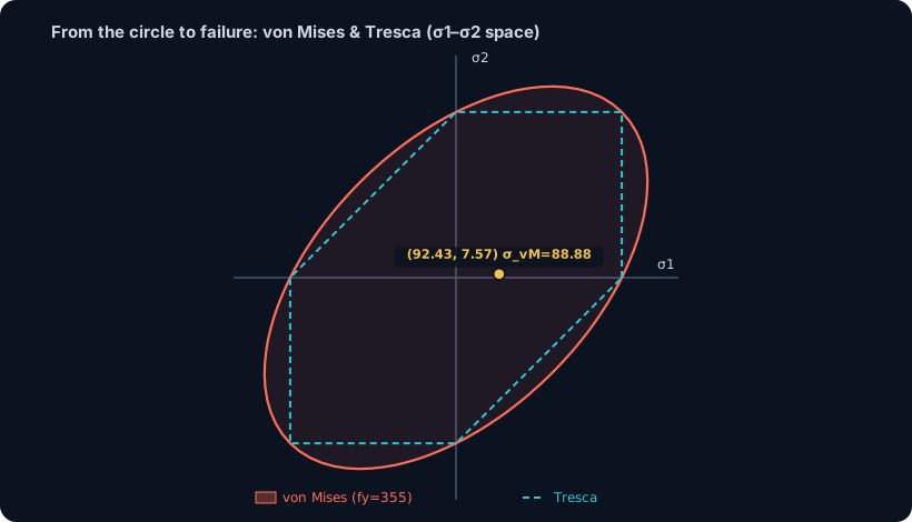
From the circle to failure: von Mises & Tresca
The Mohr's circle tells you the worst stresses and the planes they act on — but on its own it does not tell you whether the steel yields. For that you feed its principal stresses into a yield criterion, and the two that matter for structural steel both read straight off the circle.
Tresca — the maximum-shear criterion
Tresca is the honest, conservative one: yielding begins when the maximum shear stress reaches the shear yield of the material. On the circle that maximum shear is simply the radius of the largest of the three principal circles, so the criterion is τmax = (σ1 − σ3)/2, i.e. the failure measure is σ1 − σ3. It is geometrically literal — you are reading the top of the biggest circle — which is exactly why it errs on the safe side.
von Mises — the distortion-energy criterion
Steel design almost always uses von Mises, because it matches ductile-metal test data more closely. For a plane-stress state it collapses to a clean formula in the two in-plane principal stresses:
σvM = √(σ1² − σ1σ2 + σ2²)
It captures the idea that distortion, not pure volume change, drives yielding — which is why a hydrostatic point-circle (all principal stresses equal) has von Mises zero no matter how large the pressure. One caution that trips people up: von Mises is a three-dimensional criterion. In genuine plane stress the third principal stress is σ3 = 0, and it still belongs in the picture — it is the out-of-plane σ3 = 0 circle that sets the true τabs,max, and dropping it silently is one of the most common Mohr's-circle mistakes.
The code check
Design turns that stress into a single utilisation ratio η, comparing the demand against the factored yield strength fyd:
- NBR 8800: fyd = fy/γa1, with γa1 = 1.10.
- AISC 360 (LRFD): fyd = φ·fy, with φ = 0.90.
Put the canonical worked state through it — σx = 80, σy = 20, τxy = 30 MPa, giving σ1 = 92.43 MPa and σ2 = 7.57 MPa. Its von Mises stress is σvM = √(92.43² − 92.43·7.57 + 7.57²) = 88.88 MPa. For grade S355, the NBR 8800 check is η = 88.88 / (355/1.10) = 88.88 / 322.7 = 0.28. The member is at 28% of yield — comfortably safe. Notice how far apart the numbers are: σ1 = 92.43 MPa but σvM = 88.88 MPa. Principal stress is not von Mises — the criterion blends σ1 and σ2, and only the von Mises value belongs in the code check.
This is the exact number the CalcSteel engine computes at every fibre, and in the next section you will watch that same von Mises value paint the verification colours on a real 3-D steel building. You can reproduce the 88.88 MPa yourself in the free Mohr's circle calculator — it reports both σ1/σ2 and the von Mises utilisation side by side.
A real steel building: the governing fibre
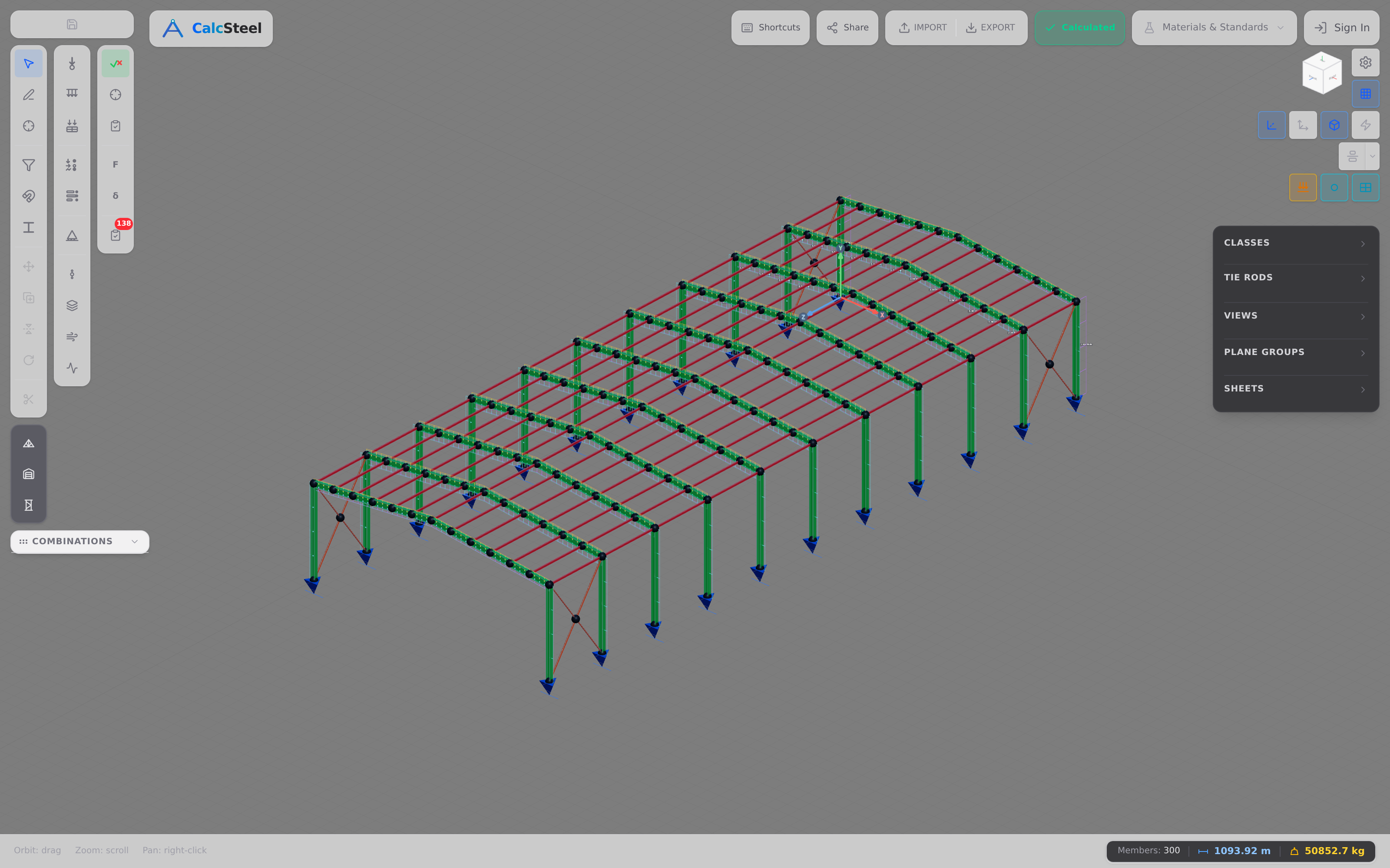
The beam-column of the last section was one member. Now scale up to a building — because the whole reason a solver builds a Mohr's circle at every fibre is so it can tell you which fibre, in which member, of a whole frame, is closest to yielding. That is the number that decides whether the steel is safe.
Take a real portal frame, IPE 330 throughout: a 12 m span, 6 m eave columns, carrying gravity w = 12 kN/m on the rafter plus a 15 kN lateral wind push, on fixed bases. This is a statically indeterminate sway frame — the rigid knees and built-in feet give more restraints than equilibrium alone can resolve, so there is no closed-form textbook formula. Only a finite-element solution gets the answer, and the CalcSteel engine returns clean base reactions as a first sanity check: vertical ΣFy = 144 kN (exactly w·L = 12 × 12) and horizontal ΣFx = −15 kN (balancing the wind precisely).
The governing fibre
The engine scans every member and finds the worst-loaded fibre at the rafter mid-span: an axial N = −15.3 kN combined with a bending moment M = 184.7 kN·m. Fed through σ = N/A − M/Sx on the IPE 330 (A = 62.6 cm², Sx = 685.9 cm³), that extreme fibre reaches:
- σx = −271.7 MPa — a nearly uniaxial compression, so the Mohr circle passes essentially through the origin.
- von Mises σvM = 271.7 MPa — for uniaxial stress the von Mises value equals the stress magnitude itself.
- Utilization η = 271.7 / (355 / 1.10) = 0.842 to NBR 8800 (γa1 = 1.10), or η = 271.7 / (0.90 × 355) = 0.850 to AISC 360 (φ = 0.90).
The member passes, but only just — at roughly 84% utilised it is an amber, well-worked section, exactly the sort you want in an efficient design: no wasted steel, real margin still in hand.
Why frame action matters
Here is the story the circle tells. If that same 12 m rafter were a simply-supported beam under w = 12 kN/m, its mid-span moment would be the textbook wL²/8 = 12 × 12² / 8 = 216 kN·m. Bent into a rigid frame, the stiff knees pull moment out of the span and share it around the corners, so the governing rafter moment drops to 184.7 kN·m. That redistribution — the reason portal frames are so efficient, and the reason they need a solver — is unpacked fibre by fibre in our shear & bending moment pillar.
The punchline that ties this whole guide together: the engine turns that single governing fibre into a Mohr's circle, reads its principal stresses, computes σvM = 271.7 MPa, and that exact von Mises value is what paints the verification colours on the 3-D model in the CalcSteel editor — green for comfortable, amber for well-utilised, red for overstressed. The circle you learned to draw by hand is the same one colouring every bar of a real steel building.
Common mistakes & FAQ
The construction is clean, but the same handful of slips catch students and practising engineers alike. Run through this checklist before you trust any circle you draw — or read off a solver.
- Confusing the angle: it's 2θ on the circle, not θ. Rotating the physical plane by an angle θ sweeps twice that angle around the circle. A 45° rotation of the element is a 180° trip across the diagram — which is exactly why the maximum-shear plane and the principal plane sit 45° apart in space but 90° apart on the circle.
- Getting the shear-plotting sign wrong. To make a physical counter-clockwise rotation read as a counter-clockwise sweep on the circle, plot the X face at (σx, −τxy) and the Y face at (σy, +τxy). Flip that sign and your angles come out with the wrong handedness even though σ1 and σ2 still look right.
- Putting τmax on the principal plane. The maximum in-plane shear acts on a plane 45° from the principal plane (θs = θp − 45°), at the top and bottom of the circle — never where σ1 and σ2 live. On the principal planes the shear is exactly zero.
- Forgetting the out-of-plane σ3 = 0 circle. For a plane-stress state the true absolute maximum shear is often set by the third circle through σ3 = 0, not the in-plane one. In our worked state τmax in-plane is 42.43 MPa, but τabs,max = σ1/2 = 46.21 MPa — and that larger value is what a Tresca check actually uses.
- Treating principal stress as the failure number. σ1 is the largest normal stress, but ductile steel yields on distortion energy: the check runs on von Mises σvM = √(σ1² − σ1σ2 + σ2²), not σ1 alone. In our example σ1 = 92.43 MPa but σvM = 88.88 MPa — they are simply different quantities.
- Expecting shear somewhere on a point-circle. An equal-biaxial (hydrostatic in-plane) state collapses the circle to a single point of radius zero. Every plane then carries the same normal stress and zero shear — there is no orientation that produces any shear at all.
Is Mohr's circle still used today?
Yes — constantly, though rarely with pencil and compass. The construction is the visual grammar behind every stress check: a solver computes the stress tensor at each fibre and reduces it exactly the way the circle does, to principal stresses and a von Mises value. Engineers still reach for the circle to reason about combined states, to sanity-check software, and to teach the geometry of stress. Draw one yourself in the free Mohr's circle calculator and the 140-year-old picture appears in real time.
What are principal stresses, physically?
They are the largest and smallest normal stresses at a point, and they act on the two planes where the shear stress vanishes completely. Rotate your imaginary cut until nothing is trying to slide the faces past each other — pure push or pull remains — and those pure-normal values are σ1 and σ2. On the circle they are simply the two points where it crosses the σ-axis. They matter because cracks tend to open perpendicular to σ1, and yield criteria are built from them.
Why is the angle doubled on the circle?
Because the stress-transformation equations for σ and τ are functions of 2θ — they contain cos 2θ and sin 2θ, not cos θ and sin θ. Mohr's circle is just the geometric picture of those equations, so a physical rotation of θ necessarily maps to an arc of 2θ. It isn't a convention you could choose differently; it falls straight out of the algebra of rotating a symmetric tensor.
Is there a Mohr's circle for strain?
Yes. The same construction works with normal strain ε on the horizontal axis and half the shear strain (γ/2) on the vertical. It gives principal strains and the maximum shear strain in exactly the same way, which is precisely how a strain-gauge rosette is reduced to principal values. The geometry is identical — only the labels on the axes change.
Key takeaways
You have travelled the whole road — from a little square element with σx, σy and τxy on its faces, to the governing fibre of a real steel frame and the code check that keeps it standing. Here is what to carry away.
- A point feels a 2-D state, not a single stress. Every plane through it maps to one point on a circle centred at σavg with radius R = τmax. Reading the circle tells you the worst plane at a glance.
- The circle hands you the design numbers directly. The two σ-axis crossings are the principal stresses (σ1 = 92.43, σ2 = 7.57 MPa in our worked state); the top of the circle is the in-plane τmax = 42.43 MPa; and the sum σ1 + σ2 = σx + σy is invariant at every rotation.
- Angles double, and the shear peak is offset. Rotating the plane by θ sweeps 2θ on the circle, and the maximum-shear plane sits 45° from the principal plane — never on it. Don't forget the out-of-plane σ3 = 0 circle when you need τabs,max.
- One section can give two different circles. In a beam-column the extreme fibre gives a degenerate uniaxial circle (σ2 = −111.4 MPa, von Mises 111.4) while the neutral axis gives a genuine combined circle (σ1 = 2.47, σ2 = −26.43 MPa). A correct check looks at both.
- The circle ends in a failure check. Its principal stresses feed von Mises σvM = √(σ1² − σ1σ2 + σ2²), and η = σvM / fyd decides the member — 0.842 to NBR 8800, 0.850 to AISC 360 for the real portal frame's governing fibre.
Now stop reading and start drawing. Load your own σx, σy and τxy into the free Mohr's circle calculator — unlimited, no login for the math — drag the shear and watch σ1, σ2 and θp respond, then load a real solved FEM section and go triaxial. When you are ready for the whole member, the CalcSteel solution runs the same real FEM engine on complete beam-columns and portal frames right in your browser, on a genuinely free plan, colouring every bar by the exact von Mises value the circle produces. Students get everything unlocked through CalcSteel Education, free for verified accounts. The proof isn't a countdown — it's the tool itself, in your hands today.
Sources
Try CalcSteel for free
Model, analyze and design steel structures in your browser. No install, no signup.
Open the 3D editor