Erection Bracing: The Frame Is at Its Weakest Before It Is Finished
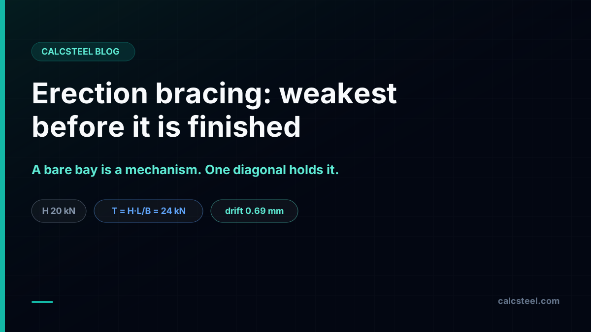
A steel frame is not stable the moment its last column is plumbed. Between erection and completion it passes through a window where the shear connections carry no moment, the floor diaphragm does not exist yet, and the permanent bracing is not in place, so the bare bay is a mechanism with almost no lateral stiffness. This guide puts numbers on that window with the CalcSteel engine: a bare 6 by 4 m bay is singular, one temporary diagonal carries 24 kN and cuts the sway to under a millimetre, and it shows how the codes make holding the frame up the erector's job.
Key takeaways
- A partially erected frame with shear connections and no bracing or diaphragm is a mechanism. On the engine the bare 6 by 4 m bay has a singular stiffness matrix (rcond about 1.2e-19), so a 20 kN construction wind produces unbounded sway. Nothing structural resists lateral load until you add it.
- One temporary diagonal turns the mechanism into a stable braced bay. The brace force is set by statics, T = H L / B: for H = 20 kN it is 24.0 kN in tension (engine and hand agree to three decimals), and the drift drops to 0.69 mm.
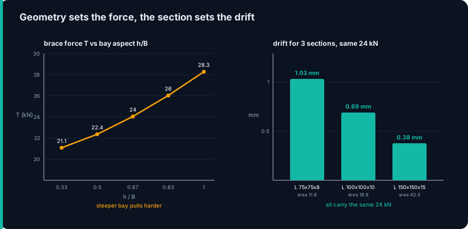
- The brace force does not depend on the brace section, only on geometry. A steeper bay pulls harder: T rises from 21.1 kN at h/B = 0.33 to 28.3 kN at h/B = 1.0. The section controls stiffness and drift, not force.
- Wind is not the only construction load. The AISC erection tolerance is L/500 out of plumb, so a leaning gravity column pushes sideways on its own: 0.4 kN for a 200 kN column, present on a dead calm day, and self-amplifying through P-Delta.
- The diagonal is rarely the weak link, its connection is. The 24 kN needs one M20 bolt, but the gusset, its weld and the anchorage are the real design, and the codes (AISC Code of Standard Practice 7.10, OSHA Subpart R, ASCE 37) make temporary stability the erector's responsibility.
The half-built frame that has to stand up by itself
There is a photograph on every steel job: columns up, a few beams landed, the crane still hooked to a girder, and not one square metre of deck in place. It reads as a building. Structurally it is not one yet. The lateral system that will hold the finished building against wind and earthquake, the moment connections, the floor diaphragm, the permanent X-bracing, does not exist during erection. The shear tabs that connect beam to column carry no moment. The metal deck that will act as a diaphragm is a bundle on the ground. The permanent bracing may be scheduled for next week.
So the frame is at its weakest exactly when it is most exposed: standing in the open, full wind on bare steel with no cladding to shield it, cranes swinging loads into it, crews walking it. The thing that keeps it up in that window is not the structure on the drawings. It is the erector's temporary bracing, and it has to be designed, not improvised.
This guide is written for the student meeting frame stability for the first time and for the practising or freelance engineer who signs erection drawings. It puts hard numbers on the bare frame with the CalcSteel engine, sizes one temporary diagonal by hand and by machine, and walks through what the codes actually require.
What erection bracing is, and what it is not
Erection bracing is temporary bracing that the erector installs to keep the frame stable during construction, and removes once the permanent lateral system is complete. Guy cables and wire rope, plumbing-up cables, temporary diagonals of angle or pipe or rod, spreader and shoring: all of it exists only for the construction stage.
It is not the permanent bracing, even when it lives in the same bay. The permanent lateral system, the moment frames, the vertical X-braces, the shear walls, the floor diaphragm, is designed by the engineer of record for the finished structure and its 50-year loads. Erection bracing is designed for a different structure (a bare, incomplete frame) under different loads (construction wind, erection operations, out-of-plumb), for a short exposure, and it is usually the erector's responsibility, not the engineer of record's. That split of responsibility is written into the AISC Code of Standard Practice, and it catches people out.
It is also not the same problem as stability bracing of a single member. Bracing a column at its midheight so it buckles in a shorter mode is a member problem governed by stiffness and strength (covered in our post on what a brace must deliver). Erection bracing is a frame problem: the whole bay is trying to rack, and we have to stop it.
Why a bare bay has almost no lateral stiffness
Three things that the finished building relies on are all missing at once during erection. First, the beam-to-column connections are shear connections: bolted shear tabs or double angles that are close to true pins. They transmit shear, not moment, so there is no portal action holding the bay square. Second, the floor diaphragm does not exist: the deck is not down, or is down but not yet fastened, so this bay cannot lean on the next bay or on the core. Third, the permanent vertical bracing is not installed.
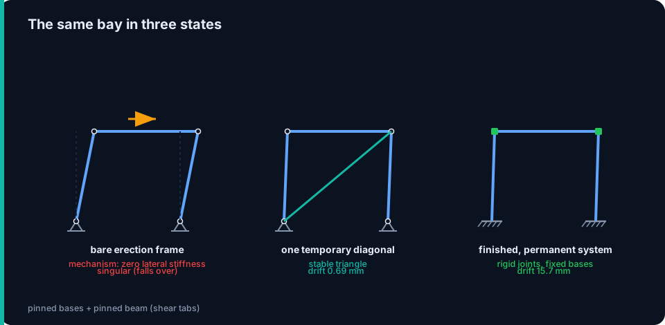
Put those together with column bases that are pinned (anchor rods set, but the frame is not a moment frame yet) and you have a single bay whose four corners are all hinges. That is a parallelogram mechanism: push the top sideways and it racks over with nothing to resist it. A mechanism has, by definition, zero lateral stiffness. It is not a weak frame, it is not yet a frame at all in the direction that matters.
Putting a number on "no stiffness"
Words like mechanism are easy to nod along to, so let us make the engine say it. Model the bare bay: HEB 200 columns 4 m tall, an IPE 300 beam over a 6 m bay, column bases pinned, and the beam ends released (rz = 0) to represent the shear connections. Apply a construction lateral load H = 20 kN at the eave and solve.
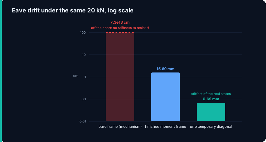
The CalcSteel linear solver reports a stiffness matrix that is singular to working precision: its reciprocal condition number is about 1.2e-19, which is machine noise, not a number. It returns a nominal drift of 7.3e13 cm, roughly 730 million kilometres. That is obviously not a displacement. It is the honest signature of a mechanism: there is no lateral stiffness for the 20 kN to work against, so the linear algebra runs off to infinity. The frame does not sway by that much, it simply falls over.
Now add one temporary diagonal and re-solve: the drift is 0.069 cm, 0.69 mm. For contrast, the fully finished moment frame (fixed bases, rigid joints) drifts 1.57 cm under the same 20 kN. The bar chart tells the whole story on a log scale: the bare mechanism is off the top, and the single diagonal is already stiffer than the finished moment frame. This is exactly what "at its weakest before it is finished" means, measured.
The loads that arrive before the frame is done
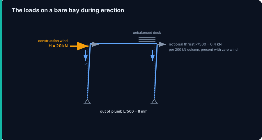
The bare frame is not sitting in still air on a level floor. Four families of load act on it during erection, and the temporary bracing has to carry all of them.
Construction wind. ASCE 37, Design Loads on Structures During Construction, lets you reduce the design wind for the short exposure period by lowering the effective recurrence interval, a factor of roughly 0.75 on the wind speed for a period up to six weeks and about 0.8 for six weeks to a year. Even reduced, it is the dominant lateral load: a bare frame is all drag and has no cladding to shelter it. We use H = 20 kN as the resultant construction lateral load on the bay; the exact value comes from the ASCE 37 combination for your site and duration.
Notional out-of-plumb load. The AISC Code of Standard Practice sets the erection tolerance at L/500 out of plumb. A 4 m column plumbed to that limit leans 8 mm at the top, and its gravity load then has a sideways component. For a 200 kN erection column that is 200/500 = 0.4 kN of lateral thrust, 0.8 kN for the two-column bay, present on a dead calm day. It is small here, but it never switches off and it is self-amplifying: the more the frame leans, the more it pushes, the classic P-Delta feedback.
Erection operations. Landing a beam, the impact of a load set down, guy pretension, crews and equipment, and eccentric hooks all add real forces the crew feels but rarely calculates.
Unbalanced gravity. Bundles of deck or stockpiled material landed on one side of the frame lean it before the wind ever arrives.
Worked example: sizing one temporary diagonal
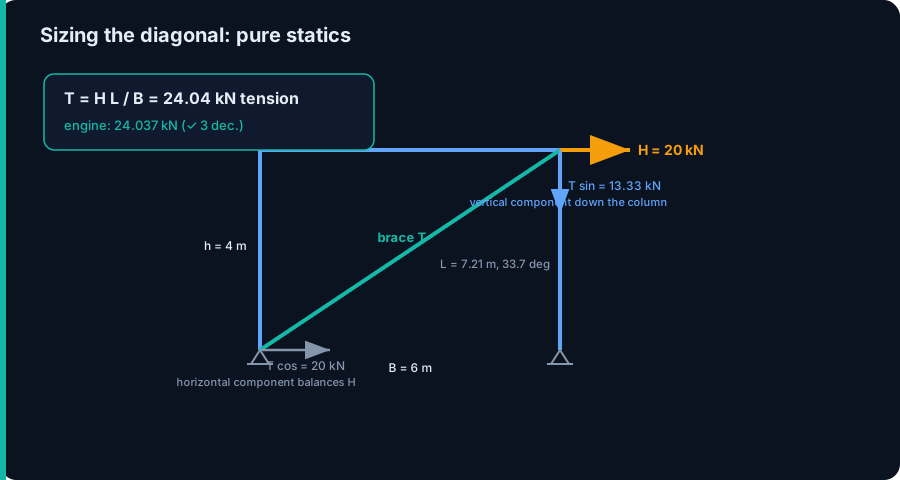
Add a diagonal from the base of one column (corner A) to the far eave (corner Ct), pinned at both ends so it is a pure two-force member. The geometry sets everything. Diagonal length L = sqrt(6^2 + 4^2) = 7.211 m, inclined at theta = 33.7 degrees above horizontal, so its horizontal cosine is B/L = 6/7.211 = 0.832.
Step 1, equilibrium. At the eave the only thing that can resist the horizontal H is the horizontal component of the brace force. So T cos(theta) = H, which rearranges to the formula worth remembering: T = H L / B. The bay geometry, not the section, sets the force.
Step 2, the number. T = 20 x 7.211 / 6 = 24.04 kN in tension. The CalcSteel engine, solving the full braced bay, returns 24.037 kN. They agree to three decimals because a single-diagonal braced bay is statically determinate: the closed form is exact.
Step 3, the vertical component. The diagonal also delivers T x (h/L) = 13.33 kN straight down the far column into the foundation. Add it to the erection gravity when you check that column and its base, because it is real axial load that only exists while the brace is in.
Notice the amplification: 20 kN of wind became 24 kN in the brace. The inclined diagonal always carries more than the horizontal load it resists, and the steeper it is, the worse that gets.
Strength is the easy part, geometry and stiffness decide the rest
Two independent facts fall out of the model, and mixing them up is where sizing goes wrong.
The force is geometry, not section. T = H L / B depends only on the load and the aspect ratio of the bay, never on what the diagonal is made of. Change the section and the force does not move. Change the shape of the bay and it does: a tall narrow bay pulls the diagonal much harder than a low wide one.
| Aspect h/B | Angle theta | Brace force T (kN) |
|---|---|---|
| 0.33 | 18.4 deg | 21.1 |
| 0.50 | 26.6 deg | 22.4 |
| 0.67 | 33.7 deg | 24.0 |
| 0.83 | 39.8 deg | 26.0 |
| 1.00 | 45.0 deg | 28.3 |
The section controls drift. Hold the load fixed and swap the diagonal: an L 75x75x8 (area 11.6 cm^2) sways 1.03 mm, an L 100x100x10 (18.75 cm^2) sways 0.69 mm, an L 150x150x15 (43.3 cm^2) sways 0.38 mm. All three carry the identical 24 kN; they differ only in how far the bay leans. Stiffness follows the axial rigidity EA/L of the diagonal.
And a counterintuitive contrast worth keeping: the single temporary diagonal (0.69 mm) is stiffer than the finished moment frame (15.7 mm), because a diagonal resists sway in pure axial stiffness while a moment frame resists it in flexure. The permanent lateral system can be softer than the temporary brace, but it only exists once its connections are made. Until then, the diagonal is the only stiffness in the bay.
Try it: put wind on a portal bay
The fastest way to feel this is to load a frame yourself. In the CalcSteel portal-frame calculator below, set a lateral load at the eave and watch the drift, then change the bay geometry and the members and see how the demand responds. Add the diagonal in your own model and the sway collapses to a fraction of a millimetre, just as it did above. It is free to use with a login.
Diagrams plotted on the deformed-free frame geometry. N, V, M recovered from the element end-forces of the direct-stiffness solve (12 elements / member). Moment drawn offset to each member's centreline.
First-order STRENGTH screening at the governing section of the NBR 8800 (BR) ULS envelope (governing CB2): N,d = 73.9 kN, M,d = 109 kN·m. Member buckling and lateral-torsional buckling are NOT included — see the stability flags below and run the full verification in the 3D editor. Click a card to make that resistance code govern the ranking.
ULS load combinations — NBR 8800 (BR)
G + W superposed · 3 combinations| Combination | Factors | Utilization |
|---|---|---|
| CB1 | 1.4 G | 69% |
| CB2governs | 1.4 G + 1.4 W | 76% |
| CB3 | 1 G + 1.4 W | 57% |
Combinations generated by the CalcSteel combinations engine (the same v4 engine the 3D editor uses, 6 codes). Gravity is treated as a single permanent action G; the wind action W is the eaves load. Each combination's γ factors are applied by superposition to the isolated gravity and wind solves, then every section is screened — the worst point of the worst combination governs.
Stability screening (buckling caveats)
not in the strength checkScreening indicators only — assumed sway effective length (K = 1.5) and the full member length as the unbraced length (no intermediate purlin/girt restraint). The strength check above deliberately excludes these; the real member verification (effective lengths from the alignment chart / notional loads, χ and Cb reduction factors, purlin bracing) runs in the 3D editor.
Lightest sections that pass (NBR)
screened 974 profiles| Profile | Mass | Frame steel | Utilization | |
|---|---|---|---|---|
| VS 400x32 | 31.9 kg/m | 723 kg | 82% | |
| VS 350x33 | 33.2 kg/m | 752 kg | 86% | |
| VS 400x34 | 34.4 kg/m | 779 kg | 75% | |
| VS 350x35 | 35.1 kg/m | 795 kg | 80% | |
| VS 400x35 | 35.1 kg/m | 795 kg | 73% |
The weak link is the connection, not the diagonal
Here is the trap in the numbers. The 24 kN brace force is tiny for structural steel. One M20 A325-N bolt in single shear has a design capacity of about 87.6 kN, so a single bolt carries the whole brace at 27 percent utilisation, and the two-bolt detailing minimum sits at 14 percent. The diagonal itself, an ordinary angle, is nowhere near its limit. If you only sized the member, you would conclude erection bracing is trivial.
It is not, because the member is not what fails. Construction-stage failures cluster in the parts around the diagonal: the gusset plate and its weld; the number of bolts actually installed (crews under-bolt temporary work to speed erection and removal, so the joint that was drawn with two bolts goes in with one); the base connection that has to take the 13.3 kN vertical component and any net uplift; and the guy anchorage, the deadman or the existing slab the cable is tied to. A field-bolted temporary connection also has slip and hole clearance, which quietly softens the very stiffness the brace was there to provide.
Size the connection for the full brace force with margin, count on the bolts actually being installed, design the anchorage as carefully as the diagonal, and make removal part of the plan rather than an afterthought.
Who is responsible, and what the codes say
Temporary stability is not a judgement call left to the crew. Three documents govern it.
AISC Code of Standard Practice, Section 7.10. Temporary supports, the guys, braces, falsework and shoring for the structural steel frame, are the erector's responsibility, and the erector determines them. In return, the engineer of record must identify in the contract documents any condition where the completed steel frame is not self-supporting and relies on other elements (a concrete core, the diaphragm, walls) for stability. The same document sets the erection tolerance of L/500 out of plumb that drives the notional load above.
OSHA 29 CFR 1926 Subpart R, Steel Erection. Columns must be anchored by a minimum of four anchor rods and designed to resist a specified minimum eccentric gravity load during erection; guying and bracing must be maintained until the structure is permanently stable; and there are rules on landing loads and on plumbing-up. These are legal minimums in the United States, not best practice.
ASCE 37, Design Loads on Structures During Construction. Gives the construction load combinations and the reduced construction wind used above. Salmon, Johnson and Malhas, Steel Structures: Design and Behavior, sets the theory in chapter 16, the distinction between braced and unbraced frames and what stability actually requires. The through-line: temporary stability is designed, documented and owned by a named party, not assumed.
Bracing follows the erection sequence
Temporary bracing is installed and removed on a schedule tied to the erection sequence, not all at once. Plumbing-up cables go on as columns rise. A braced bay is established early, and the rest of the floor is hung off it and plumbed back to it. Temporary diagonals stay until the permanent lateral system, or the deck diaphragm, is not just placed but connected, and only then are they released.
The handoff is the dangerous moment. Remove the temporary brace before the permanent system is actually fastened and you reopen the mechanism from the start of this article, now with more weight on it. Decking that is laid loose is not a diaphragm until it is puddle-welded or fastened; a permanent brace bolted up but not fully tensioned is not yet doing its job. Sequence the removal as deliberately as the installation, and tie both to inspected milestones.
How erection bracing quietly fails
The recurring failure modes are not exotic. They are these.
Removing the brace too early. Releasing the temporary diagonal before the permanent system is connected is the classic collapse trigger, because it puts the mechanism back with the structure fully loaded.
No redundancy. One brace per bay means one connection failure reopens the mechanism. A second diagonal or a second braced line is cheap insurance during the most vulnerable stage.
Ignoring the notional load and P-Delta. Bracing sized for wind alone forgets that an L/500 lean pushes sideways on a calm day, and that the push grows as the frame leans.
Under-bolting to save field time. The diagonal is strong, but a joint drawn for two bolts and built with one loses both strength and stiffness.
Weak anchorage. The diagonal checks out and the deadman or the slab it is guyed to does not. The load has to go somewhere real.
Calling loose deck a diaphragm. Deck that is placed but not fastened carries no in-plane shear, so the bay is still on its temporary bracing whether the schedule says so or not.
The deeper reason these keep happening is psychological: a frame standing in the air looks finished, so everyone assumes it is a building. It is at its weakest precisely then.
Key takeaways
A steel frame is not stable until its lateral system is complete and connected, and it spends real time in a window where none of that is true. In that window it is the erector's temporary bracing that holds it up.
- A bare bay with shear connections and no bracing or diaphragm is a mechanism: on the engine it is singular, with no lateral stiffness at all.
- One temporary diagonal fixes it. The force is pure statics, T = H L / B, 24 kN for a 20 kN wind on this bay, and it drops the sway to under a millimetre.
- Geometry sets the force, the section sets the drift, and a steeper bay pulls the diagonal harder.
- Wind is not the only load: the L/500 out-of-plumb lean pushes sideways on a calm day and feeds P-Delta.
- The diagonal rarely governs, its connection and anchorage do, and the codes make the whole thing the erector's designed, documented responsibility.
Sources
- 1.AISC 303, Code of Standard Practice for Steel Buildings and Bridges, Section 7.10 (Temporary Support of Structural Steel Frames) and erection tolerances
- 2.OSHA 29 CFR 1926 Subpart R, Steel Erection (column stability, anchor rods, guying and bracing)
- 3.ASCE/SEI 37, Design Loads on Structures During Construction (construction load combinations and reduced construction wind)
- 4.Salmon, Johnson and Malhas, Steel Structures: Design and Behavior, chapter 16 (frame stability, braced and unbraced frames)
Try CalcSteel for free
Model, analyze and design steel structures in your browser. No install, no signup.
Open the 3D editor