Where Structural Engineers Actually Use Integrals: Area, Centroid & Deflection
You met the integral as the area under a curve. In structural engineering it is a tool you reach for on almost every project: to add up an area, to find where a section balances, to measure how stiff it is, and to predict how far a beam will sag. This guide walks through the integrals in structural engineering that actually earn their keep, with worked steel examples and a free live calculator you can drive as you read.
Key takeaways
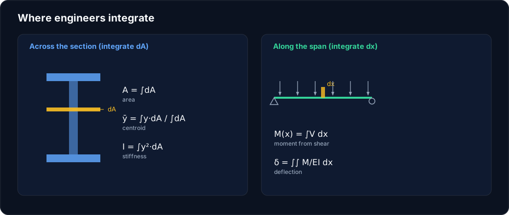
- Structural engineers integrate in two places: across a cross-section (the dA integrals) and along a member (the dx integrals).
- Area A = ∫dA, first moment and centroid ȳ = ∫y·dA / ∫dA, and second moment I = ∫y²·dA are all integrals over the section, and they set self-weight, the neutral axis and bending stiffness.
- The centroid is where the section balances, not the mid-height: for the worked tee it sits 150 mm up a 200 mm section, so the neutral axis is nowhere near the middle.
- Deflection is a double integral of the bending moment: EI·v′′ = M(x), so you integrate M twice to get the shape the beam takes.
- CalcSteel does these integrals for you: for a 6 m beam under 10 kN/m it returns a midspan deflection of 10.4 mm, matching the closed-form 5wL⁴/384EI to three decimals.
The integral you learned, and the beam you will design
Somewhere in a first calculus course you were told that an integral is the area under a curve, and you dutifully computed ∫x² dx for problems that never mentioned a beam, a bolt or a building. It is a fair question to ask what any of it has to do with engineering. The honest answer is: almost everything. The integral is the mathematics of adding up something that changes continuously, and a steel structure is full of quantities that change continuously across a section or along a span.
This article is a tour of where integrals in structural engineering genuinely show up, aimed at the student who wants the payoff and at the practising engineer who wants to see the same ideas in software. We will keep the calculus light and the examples concrete: a welded steel tee, a rolled I-beam, real numbers, and diagrams generated by the same finite-element engine that powers CalcSteel. By the end, ∫ will stop being an exam symbol and start being the reason a section table has the columns it does.
Two places engineers integrate: the section and the span
Before the formulas, hold on to one mental map. Structural engineers integrate in exactly two settings, and every quantity below belongs to one of them.
- Across the cross-section, integrating over the little areas dA that make up the shape. This is how we get the area, the centroid (where the section balances) and the second moment of area (how stiff it is in bending). These are the numbers printed next to every profile in a steel catalogue.
- Along the member, integrating over the length dx as you walk from one end of a beam to the other. This is how shear becomes moment, and how moment becomes slope and then deflection. These are the numbers a solver reports along a bar.
Same operator, two domains. The cross-section integrals describe the shape of the steel; the span integrals describe the response of the beam. Keep that split in mind and the rest of the article is just filling in the four integrals that matter most.
Integral 1: area, A = ∫dA
The simplest integral in the whole subject is also the one you use first on every job. The cross-sectional area is A = ∫dA, the sum of every infinitesimal patch of material in the section. For a shape you can slice into rectangles you never see the integral sign, because ∫dA collapses to a sum of width times height. But it is an integral, and it is doing real work.
Two everyday numbers fall straight out of it. First, self-weight: multiply the area by the steel density and you get mass per metre (a plate girder web of 8 mm by 468 mm weighs 0.008 × 0.468 × 7850 ≈ 29 kg per metre). Second, axial stress, σ = N / A: the area is the denominator that turns a force into a stress a code can check. Get the area wrong and every stress downstream is wrong with it.
Integral 2: the centroid, ȳ = ∫y·dA / ∫dA
Here the integral starts to reveal something you cannot guess. The centroid is the height at which the section balances, and it is defined by the first moment of area: ȳ = ∫y·dA / ∫dA. Each patch of material dA is weighted by its distance y from a reference line, summed, and divided by the total area. Bending happens about the axis through the centroid, so finding it is not optional: it is where the neutral axis lives.
Worked example: a welded tee
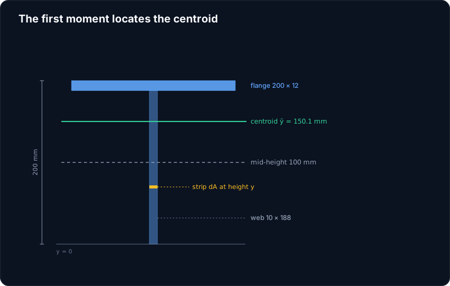
Take a tee welded from two plates: a flange 200 mm wide by 12 mm thick on top, and a web 10 mm thick by 188 mm tall below it, for a total height of 200 mm. Split it into the two rectangles and measure y from the bottom:
- Web: area Aᵥ = 10 × 188 = 1880 mm², centroid at yᵥ = 94 mm.
- Flange: area Aᶠ = 200 × 12 = 2400 mm², centroid at yᶠ = 194 mm.
The total area is A = 1880 + 2400 = 4280 mm² (42.8 cm²), and the first moment about the base is ∫y·dA = 1880 × 94 + 2400 × 194 = 642,320 mm³. Divide, and the centroid sits at:
ȳ = 642,320 / 4280 = 150.1 mm from the bottom.
Read that number again. The section is 200 mm deep, so the mid-height is 100 mm, but the centroid is at 150 mm, half the section higher. Because most of the area is bunched near the top in the flange, the balance point is pulled up with it. This is the whole reason the integral exists: for anything that is not symmetric (a tee, a channel, an angle, a crane rail) the neutral axis is not at the middle, and only ∫y·dA tells you where it really is.
The same first-moment integral, taken over just the area above a cut, is the Q in the shear-flow formula τ = VQ / (I·t). For this tee, the first moment of the flange about the neutral axis is Q ≈ 105,400 mm³, which is what sizes a welded or bolted connection between web and flange. One integral, two jobs.
Integral 3: the second moment of area, I = ∫y²·dA
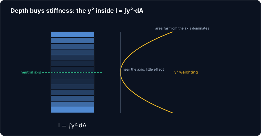
The third integral is the one that separates a floppy section from a stiff one. The second moment of area, I = ∫y²·dA, again sums the little areas dA, but now each is weighted by the square of its distance from the centroid. That square is everything. Material at 150 mm from the axis counts nine times as much as material at 50 mm, so a section gets stiff by pushing area far from the neutral axis, which is exactly why an I-beam looks like an I.
Same tee, now its stiffness
Carrying the welded tee forward, integrate y² over each rectangle about the centroid at 150.1 mm using the parallel-axis idea (each rectangle contributes its own b·h³/12 plus its area times distance-to-centroid squared):
- Web: 10 × 188³/12 + 1880 × (150.1 − 94)² ≈ 5.54×10⁶ + 5.91×10⁶ mm⁴.
- Flange: 200 × 12³/12 + 2400 × (194 − 150.1)² ≈ 0.03×10⁶ + 4.63×10⁶ mm⁴.
Add them: I ≈ 16.1×10⁶ mm⁴, or 1611 cm⁴. Notice the flange contributes almost nothing through its own b·h³/12 (it is thin), but a great deal through the A·d² term, because it sits far from the axis. The y² inside the integral is the reason. That single number then drives two of the most-used checks in the book: the bending stress σ = M·y / I and, as we are about to see, the deflection.
Try it: compute area, centroid and I live
You do not have to grind these integrals by hand every time. The moment of inertia calculator below runs the same ∫dA, ∫y·dA and ∫y²·dA over any of nine standard shapes, or over a custom section you build from plates, and reports the area, the centroid, the second moment I, the section modulus and the radius of gyration, drawn to scale. Rebuild the welded tee from the worked example (a 200 × 12 flange and a 10 × 188 web) and you will see the centroid land at 150 mm and I at about 1611 cm⁴, the numbers we just integrated.
Formula — hover a variable to highlight it on the drawing
Ix = [ b·h³ − (b − tw)·hw³ ] / 12= 1,845.6 cm⁴(hw = h − 2·tf)
Iy = [ 2·tf·b³ + hw·tw³ ] / 12= 141.9 cm⁴
Root fillets are neglected — rolled-section tables run 1–5% higher on Ix.
Parallel-axis theorem, live — Ix = Σ ( I₀ + A·d² )
| Part | A (cm²) | d (cm) | I₀ (cm⁴) | A·d² (cm⁴) | I₀ + A·d² (cm⁴) |
|---|---|---|---|---|---|
| Web | 10.25 | 0 | 286 | 0 | 286 |
| Flange (top) | 8.5 | 9.58 | 0.512 | 779.3 | 779.8 |
| Flange (bottom) | 8.5 | 9.58 | 0.512 | 779.3 | 779.8 |
| Σ = Ix | 287 | 1,558.6 | 1,845.6 |
Exact rectangle parts (web + two flanges) about the section centroid — the flange A·d² transfer terms are the whole story of the I-beam. Change any dimension above and watch the table re-derive.
Section properties
Moment of inertia Ix
1,845.6 cm⁴
1.846 × 10⁷ mm⁴
Moment of inertia Iy
141.9 cm⁴
1.419 × 10⁶ mm⁴
Area A
27.25 cm²
Mass
21.39 kg/m
Section modulus Sx
184.6 cm³
Section modulus Sy
28.39 cm³
Plastic modulus Zx
209.7 cm³
Plastic modulus Zy
43.93 cm³
Radius of gyration rx
8.23 cm
Radius of gyration ry
2.28 cm
Centroid x̄ (from left)
50 mm
Centroid ȳ (from bottom)
100 mm
Local slenderness — NBR 8800 / AISC 360 fingerprint
Flange
λ = b / 2·tf = 5.88
λp = 10.75 · λr = 28.28
Web
λ = hw / tw = 32.68
λp = 106.3 · λr = 161.2
Flexure limits per AISC 360 Table B4.1b (≈ NBR 8800 Annex F), fy = 250 MPa, E = 200 GPa — λp/λr scale with √(E/fy). Compact sections reach the full plastic moment Mp = Z·fy; non-compact and slender elements are capped by local buckling.
Closest standard profiles — matched by Ix against 876 real catalog sections
Ix = 1,845.6 cm⁴ (-0.0%)
Iy = 141.9 cm⁴ (-0.0%)
21.39 kg/mlightest
Best match — design checks
Ix = 1,844.2 cm⁴ (-0.1%)
Iy = 902.5 cm⁴ (+535.8%)
34.19 kg/m#2 by weight
Design checks
Ix = 1,838.7 cm⁴ (-0.4%)
Iy = 1,838.7 cm⁴ (+1195.4%)
43.96 kg/m#3 by weight
Design checks
Same 1,309-profile database that powers the CalcSteel 3D editor and profile pages — ABNT cold-formed (Ue, U, rounds), AISC (W, HSS, L, Pipe), European (IPE, HEA, HEB, HEM, UPN) and Indian (ISMB/ISMC) series. Opening a match carries your custom section along as the comparison baseline.
Along the span: moment is the integral of shear
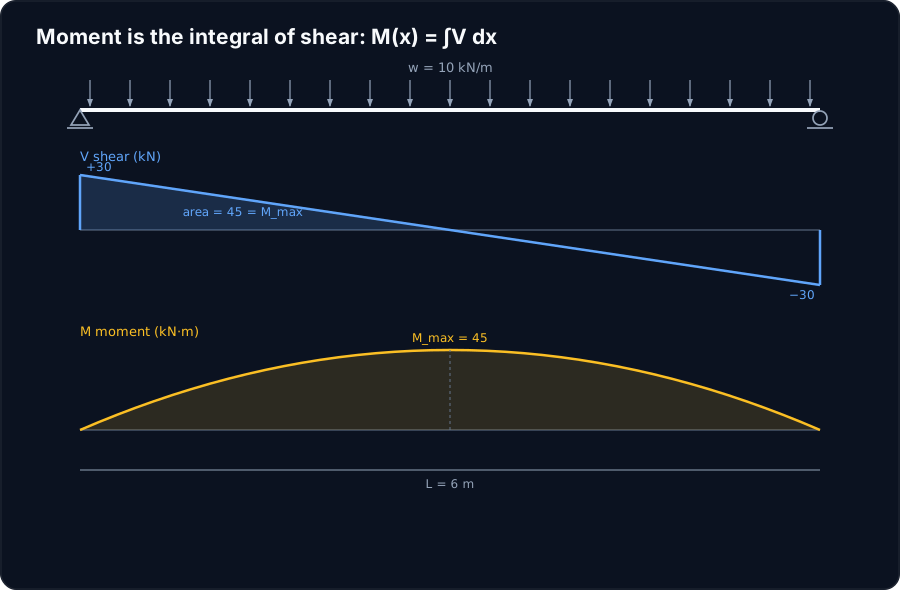
Now switch domains, from integrating across the section to integrating along the beam. The first span integral is a quiet one you have probably used without naming it: the bending moment is the running integral of the shear, M(x) = ∫V dx. The moment at any point is the accumulated area under the shear diagram up to that point.
Take a simply supported beam of span L = 6 m carrying a uniform load w = 10 kN/m. The reactions are each wL/2 = 30 kN, so the shear starts at +30 kN, falls in a straight line through zero at midspan, and reaches −30 kN at the far support. The moment is the area under that shear line. From the support to midspan the shear traces a triangle of area ½ × 30 × 3 = 45, so the moment climbs to M_max = wL²/8 = 45 kN·m at the centre, then falls back by symmetry. The moment diagram is a parabola precisely because you are integrating a straight line.
This is the same pair of relations that drive shear and moment diagrams, dV/dx = −w and dM/dx = V, read as integrals rather than derivatives. If you want the full treatment of drawing those diagrams, see our companion guide on shear force and bending moment diagrams. Here the point is narrower: the climb from shear to moment is an integral along dx.
The big one: deflection is a double integral
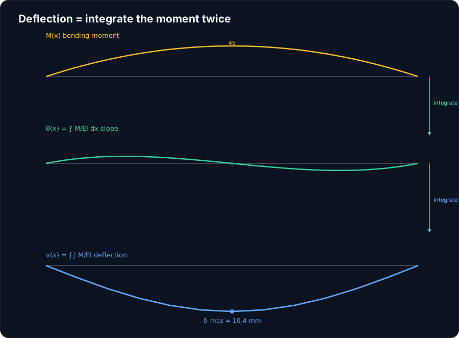
This is where the integral pays for all those calculus problems. How far a beam sags is governed by the elastic curve equation, EI·v′′(x) = M(x), where v is the vertical deflection and EI is the bending stiffness (the E of the steel times the I we just integrated over the section). Read it as an instruction: to get the deflected shape v, you integrate the moment twice. Integrate M(x) once and you get the slope of the beam; integrate again and you get the deflection itself. Two integrations, two constants fixed by the supports.
Worked example: a 6 m beam under uniform load
Take the same simply supported span, L = 6 m, w = 10 kN/m, this time as a real rolled IPE 300 in steel with E = 200 GPa and a second moment of area I ≈ 8.1×10³ cm⁴ (the ∫y²·dA of the previous section, as CalcSteel models the section). Double-integrating the parabolic moment and applying the pinned supports gives the textbook closed form for the midspan deflection:
δ_max = 5wL⁴ / (384·EI) = 10.4 mm.
We did not stop at the formula. Modelling this beam in CalcSteel's finite-element engine, which builds the same integral numerically over a mesh of the member, returns a midspan deflection of 10.42 mm, matching the hand double-integration to three decimals. That agreement is the point: the closed form and the solver are computing the same ∫∫M/EI, one on paper and one on a mesh.
Try it, and why the number matters
A cantilever makes the double integral even starker. Fix one end of a 2.5 m arm and hang a 12 kN load at the tip, and integrating EI·v′′ = M twice gives δ = PL³ / (3EI). For the same IPE 300 that is 3.86 mm at the tip, and CalcSteel's engine returns 3.86 mm as well. Different support conditions, different constants of integration, same operation.
The reason engineers care about the exact value is serviceability. A floor that is strong enough can still be unusable if it bounces or cracks the ceiling below, so codes cap deflection at a fraction of the span, commonly L/250 or L/360. For the 6 m beam, L/360 is 16.7 mm and L/250 is 24 mm; our 10.4 mm sits comfortably under both, with the span-to-deflection ratio at about 576. That check, pass or fail, rests entirely on a double integral. Set up your own span below and watch the deflection move as you change the load, the length and the section.
Max moment
45 kN·m
Max shear
30 kN
Max deflection
10.55 mm
= L/569
Bending stress σ
84.4 MPa
σ = M/Sx
Utilization
44.0%
NBR 8800 · δ ≤ L/250
Geometry & supports
Section
Ix 7999 cm⁴ · Sx 533 cm³ · 42.2 kg/m
Point loads (↓ positive)
None — add as many as you need.
Distributed loads (uniform or trapezoidal)
Model sketch
Diagrams — free PNG / SVG / CSV export, no watermark
Step-by-step — the calculation memory of YOUR beam
IPE 300 · L = 6 m · fy = 250 MPa
1. Reactions (equilibrium of the solved FEM model)
ΣFy = 0 · ΣM = 0
R_A = 30 kN · R_B = 30 kN
2. Peak shear (read from the SFD)
Vmax = |V(x)|max
Vmax = -30 kN @ x = 6 m
3. Peak moment (read from the BMD)
Mmax = |M(x)|max
Mmax = 45 kN·m @ x = 3 m
4. Peak deflection
EI = 15998 kN·m² (E = 200 GPa)
δmax = 10.55 mm @ x = 3 m = L/569
5. Elastic bending stress
σ = Mmax / Sx = 45.00 × 10³ / 533.3
σ = 84.4 MPa
6. Bending check — both codes, side by side
NBR 8800: σ ≤ fy/1.10 = 227.3 MPa · AISC 360: σ ≤ 0.90·fy = 225 MPa
NBR 37.1% PASS · AISC 37.5% PASS
7. Deflection check (serviceability — code-independent)
δ ≤ L/250 = 24 mm
10.55 mm / 24 mm = 44.0% PASS
Recomputed live from the current inputs by the direct-stiffness FEM engine — change any load and every step updates. Reproduce it by hand with the formulas in the sections below.
Lightest catalog profiles that pass (974 flexural candidates · NBR 8800)
| Profile | Std | Weight | Total steel | σ util | δ util | |
|---|---|---|---|---|---|---|
| W310x21 | AISC | 21 kg/m | 126 kg | 83% | 98% | |
| VS 300x23 | BR | 22.6 kg/m | 136 kg | 71% | 84% | |
| U 300x90x6.3 | BR | 23.1 kg/m | 139 kg | 82% | 98% | |
| U 300x100x6.3 | BR | 24.1 kg/m | 145 kg | 77% | 91% | |
| VS 250x25 | BR | 24.6 kg/m | 148 kg | 70% | 100% |
Elastic bending (σ = M/Sx vs fy/γa1, γa1 = 1.10 — NBR 8800) + deflection screening of the full flexural catalog. Lateral-torsional buckling, shear and local buckling are NOT checked here — run the full NBR 8800 / AISC 360 verification in the 3D editor.
Common mistakes, and a few honest caveats
- Assuming the centroid is at mid-height. True only for doubly symmetric sections. For a tee, channel, angle or any built-up shape you must take ∫y·dA. Our tee proved the point at 150 mm on a 200 mm section.
- Forgetting the A·d² term. The second moment of a part about the whole section's centroid is its own b·h³/12 plus area times distance squared. Drop the transfer term and a flange contributes almost nothing, which is badly wrong.
- Mixing units. Keep one system to the end. Steel tables list I in cm⁴ and stress in MPa, while a solver may work in mm or metres. A stray factor of ten in I becomes a factor of ten in deflection.
- Expecting a table and a solver to agree to the last digit. Real rolled sections have tapered flanges and root fillets, so a section table (which integrates the true rolled shape) and a simplified model can differ by a few percent on I. That gap is not a bug, it is the reason serious work integrates the real geometry instead of trusting an eyeballed rectangle.
- Thinking the maximum deflection is under the maximum load. Deflection is the double integral of moment over the whole span, so its peak depends on the entire loading and the supports, not on any single point.
Key takeaways
Integrals in structural engineering are not decoration. They are how a section becomes a set of properties and how a load becomes a shape. Master the two domains, dA across the section and dx along the span, and the four integrals below carry most of everyday analysis. The next time software hands you an area, a centroid, an I and a deflection in a fraction of a second, you will know exactly which integral it just did on your behalf.
Sources
Try CalcSteel for free
Model, analyze and design steel structures in your browser. No install, no signup.
Open the 3D editor