Column Base Plate Design: Bolts & Thickness
The base plate is where steel meets concrete — and where many design mistakes hide. An undersized plate crushes the concrete, bolts too small let the column lift in wind uplift, and a plate too thin bends like a diving board. This guide walks through AISC Design Guide 1 step by step: bearing pressure, plate dimensions, plate thickness, and anchor bolts, with a complete worked example on a W310×97 column.
Key takeaways
- Base plate area is governed by concrete bearing capacity: φc Pp = φc × 0.85f'c × A1 × √(A2/A1), where the confinement factor √(A2/A1) can double the capacity.
- Plate thickness is governed by cantilever bending of the plate beyond the column footprint. The critical cantilever distances m and n (AISC DG1) determine the required tp.
- Anchor bolts resist uplift (tension) and lateral forces (shear). For pinned bases, 4 bolts inside the column flanges are standard; for moment bases, bolts outside the flanges are needed.
- CalcSteel pre-dimensions base plates at every support: click any column base to see the required plate size, thickness, and bolt layout.
What is a column base plate in steel structures?
A column base plate is a rectangular steel plate welded to the bottom of a column that spreads the concentrated column load over a larger area of concrete. Without it, the column's small cross-section (typically 100–400 cm²) would punch through the concrete footing, which can resist only 15–40 MPa in bearing — far less than the 250–450 MPa yield stress of steel.
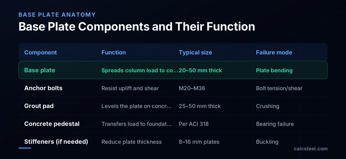
The base plate assembly has four components: the plate itself (typically 20–50 mm thick A36 or A572 steel), anchor bolts (cast into the concrete to resist uplift and shear), a grout pad (non-shrink grout that levels the plate and fills the gap between plate and concrete), and the concrete pedestal or footing (which transfers the load to the soil).
The design is governed by three limit states: concrete bearing (can the concrete support the load without crushing?), plate bending (can the plate span between the column flanges and the plate edges without excessive flexure?), and anchor bolt capacity (can the bolts resist uplift from wind or seismic overturning?). Each is checked independently, and the plate dimensions and thickness must satisfy all three.
AISC Design Guide 1 (Base Plate and Anchor Rod Design, 2nd Edition, 2006) is the primary reference. For seismic design, AISC 341 adds requirements for ductile anchor bolt detailing.

How to design a steel column base plate?
The design follows a clear sequence: bearing → plate size → plate thickness → anchor bolts. Here is the logic of each step:
Step 1 — Determine the required bearing area. The concrete bearing capacity per AISC J8 (and ACI 318 §10.14) is:
φc Pp = φc × 0.85 f'c × A1 × √(A2/A1)
where φc = 0.65, f'c = concrete compressive strength, A1 = plate area, A2 = area of the supporting concrete surface (pedestal or footing). The ratio √(A2/A1) ≤ 2.0 accounts for confinement: when the plate is smaller than the concrete surface, the surrounding concrete confines the bearing zone and increases its capacity — by up to 2×.
Step 2 — Choose plate dimensions B × N. Start with B and N each 50–100 mm larger than the column's d and bf to provide edge distance for the anchor bolts. Then check that B × N ≥ A1,required from Step 1. Round up to practical dimensions (multiples of 10 or 25 mm).
Step 3 — Calculate plate thickness. The plate acts as a cantilever loaded by the concrete bearing pressure. AISC DG1 defines two critical cantilever distances:
- m = (N − 0.95d) / 2 — overhang beyond the column depth
- n = (B − 0.80bf) / 2 — overhang beyond the column flanges
The required plate thickness is: tp = ℓ × √(2Pu / (0.9 Fy B N)), where ℓ = max(m, n, λn') and n' = √(dbf)/4.
Step 4 — Size the anchor bolts. For a pinned base under gravity only, the bolts resist construction erection loads and minor shear. For a base with net uplift (wind, seismic), the bolts must resist the tensile force Tu = Mu/lever arm − Pu (where the moment arm depends on bolt placement).
How to calculate base plate bearing pressure on concrete?
The concrete bearing check ensures the plate does not crush the concrete beneath it. The factored bearing capacity is:
φc Pp = 0.65 × 0.85 f'c × A1 × √(A2/A1) ≤ 0.65 × 1.7 f'c × A1
The confinement factor √(A2/A1) is capped at 2.0. In practice:
- If the plate sits on a wide footing (A2 ≥ 4A1), √(A2/A1) = 2.0, and the effective bearing strength doubles to 1.7 f'c.
- If the plate covers the entire pedestal (A2 = A1), there is no confinement and the bearing strength is just 0.85 f'c.
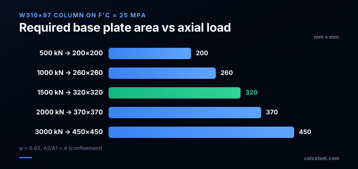
For a W310×97 column carrying Pu = 1 500 kN on f'c = 25 MPa concrete with full confinement:
A1,required = Pu / (φc × 0.85 f'c × 2.0) = 1 500 000 / (0.65 × 0.85 × 25 × 2.0) = 1 500 000 / 27.6 = 54 300 mm² → plate ≈ 240 × 240 mm minimum.
But the column dimensions are d = 308 mm and bf = 305 mm. Adding 50 mm edge distance on each side gives B = 305 + 100 = 405 mm, N = 308 + 100 = 408 mm → use B = N = 410 mm (area = 168 100 mm²). The actual bearing pressure is only Pu/A1 = 1 500/0.168 = 8.9 MPa — well below the 27.6 MPa capacity. The plate size is governed by geometry (column dimensions + bolt edge distance), not bearing.

What is the minimum base plate thickness?
The plate must be thick enough to resist bending from the upward concrete pressure. Think of the plate as a series of cantilevers extending from the column footprint to the plate edges. The concrete pushes up uniformly, and the plate bends between the column flanges/web and the free edges.
AISC DG1 calculates the required thickness as:
tp,required = ℓ × √(2 fpu / (0.9 Fy))
where fpu = Pu / (B × N) is the factored bearing pressure, ℓ = max(m, n, λn'), and:
- m = (N − 0.95d) / 2 = (410 − 0.95 × 308) / 2 = (410 − 293) / 2 = 58.7 mm
- n = (B − 0.80bf) / 2 = (410 − 0.80 × 305) / 2 = (410 − 244) / 2 = 83.0 mm
- n' = √(d × bf) / 4 = √(308 × 305) / 4 = 306.5 / 4 = 76.6 mm
The λ factor depends on the load ratio X = (4dbf / (d+bf)²) × Pu / (φcPp). For our case λ ≈ 0.7, so λn' = 0.7 × 76.6 = 53.6 mm.
ℓ = max(58.7, 83.0, 53.6) = 83.0 mm (the flange overhang governs).
fpu = 1 500 000 / (410 × 410) = 8.92 MPa.
tp = 83.0 × √(2 × 8.92 / (0.9 × 250)) = 83.0 × √(17.84 / 225) = 83.0 × 0.2815 = 23.4 mm → use 25 mm plate.
A 25 mm plate in A36 steel (Fy = 250 MPa) is reasonable. If the plate were too thick (>50 mm), stiffeners between the column flanges and the plate edges would be more economical than a thicker plate.
What are the anchor bolt requirements for base plates?
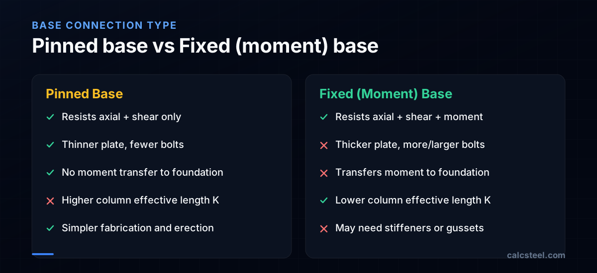
Anchor bolts serve three functions: resist uplift (wind/seismic overturning), resist horizontal shear (lateral loads at the base), and position the column during erection. The design depends on whether the base is pinned or fixed (moment-resisting).
Pinned base (gravity + minor shear): Typically 4 bolts (M20 or M24) placed inside the column flanges. For a pinned base under gravity only, the bolts are essentially erection aids — they resist incidental lateral loads and keep the column in position until the framing is complete. The shear demand is small and is typically resisted by friction between the plate and grout (μ ≈ 0.4) or by anchor bolt shear.
Fixed (moment) base: The base must transfer moment to the concrete. Bolts outside the column flanges are loaded in tension by the moment, while the opposite side bears on the concrete. The bolt tension for a moment base is:
Tu = (Mu / lever arm) − Pu,min
where the lever arm is the distance between the bolt group centroids and Pu,min is the minimum axial compression (which helps by reducing the net tension). For large moments, bolts can be M30 or M36, and stiffener plates or gussets may be needed to transfer the bolt forces into the column.
Anchor bolt material is typically F1554 Grade 36 (Fy = 248 MPa, Fu = 400 MPa) for standard applications or Grade 55 (Fy = 380 MPa) for high-load bases. The embedment depth per ACI 318 Appendix D must be sufficient to develop the bolt's tensile capacity in the concrete — typically 12–15 bolt diameters for cast-in-place headed anchors.
How to determine base plate dimensions?
The plate dimensions B (width) and N (length) must satisfy three constraints simultaneously:
- Bearing area: B × N ≥ Pu / (φc × 0.85 f'c × √(A2/A1)). This is the minimum area to avoid crushing the concrete.
- Column clearance: B ≥ bf + 2 × edge distance (typically 50–100 mm per side for bolt placement), and N ≥ d + 2 × edge distance. The plate must extend beyond the column footprint to accommodate anchor bolts.
- Balanced overhangs: AISC DG1 recommends choosing B and N so that the cantilever distances m and n are approximately equal. This minimises the plate thickness by avoiding one excessively long cantilever. The formula: B = √(A1) + Δ and N = √(A1) − Δ, where Δ = (0.95d − 0.80bf)/2.
For the W310×97: Δ = (0.95 × 308 − 0.80 × 305)/2 = (293 − 244)/2 = 24.3 mm. If A1 = 168 100 mm² (from 410 × 410), then √A1 = 410. B = 410 + 24 = 434, N = 410 − 24 = 386. Rounding: B = 440 mm, N = 390 mm (or simply B = N = 410 mm for a square plate, which is more common in practice).
In practice, base plates are almost always rectangular or square, cut from standard plate widths (300, 400, 450, 500 mm). The exact dimensions are less critical than meeting the three constraints above — bearing area, bolt clearance, and reasonable plate thickness.

How does CalcSteel design base plates?
CalcSteel includes a built-in base plate pre-dimensioning tool. When you click any column support point, the app computes the required base plate and displays it as an interactive overlay. Here is the workflow:
Step 1 — Click the support. In the 3D model, click on any column base (pin or fixed support). CalcSteel reads the factored axial load Pu, shear Vu, and moment Mu (for fixed bases) from the worst-case load combination.
Step 2 — Enter concrete properties. Specify f'c and the pedestal dimensions (A2). CalcSteel defaults to common values (f'c = 25 MPa, pedestal 2× plate in each direction).
Step 3 — Read the result. CalcSteel shows:
- Required plate dimensions B × N (rounded to practical sizes)
- Required plate thickness tp (based on the critical cantilever ℓ)
- Anchor bolt layout (number, diameter, and edge distances)
- Bearing utilisation ratio (actual/allowable pressure)
For moment bases, CalcSteel also shows the bolt tension demand and verifies that the selected bolt size has sufficient capacity.
The overlay is parametric: change f'c, adjust bolt size, or switch from pinned to fixed, and the design updates instantly. This makes it easy to optimise — for example, increasing f'c from 25 to 30 MPa might reduce the plate from 450 × 450 to 400 × 400, saving material and simplifying fabrication.

Steel column base plate design calculation step by step
Complete AISC DG1 design for a W310×97 column (A992) carrying Pu = 1 500 kN on f'c = 25 MPa concrete, full confinement (A2/A1 = 4).
Step 1 — Column dimensions. d = 308 mm, bf = 305 mm.
Step 2 — Required bearing area. A1,req = Pu / (φc × 0.85f'c × √(A2/A1)) = 1 500 000 / (0.65 × 0.85 × 25 × 2.0) = 1 500 000 / 27.6 = 54 300 mm².
Step 3 — Plate dimensions. Minimum for bolt clearance: B = 305 + 100 = 405 mm, N = 308 + 100 = 408 mm. Use B = N = 410 mm (A1 = 168 100 mm² >> 54 300 ✓).
Step 4 — Cantilever distances. m = (410 − 0.95 × 308)/2 = 58.7 mm. n = (410 − 0.80 × 305)/2 = 83.0 mm. n' = √(308 × 305)/4 = 76.6 mm. λn' ≈ 53.6 mm. ℓ = max(58.7, 83.0, 53.6) = 83.0 mm.
Step 5 — Bearing pressure. fpu = 1 500 000 / (410 × 410) = 8.92 MPa.
Step 6 — Plate thickness. tp = ℓ × √(2fpu / (0.9Fy)) = 83.0 × √(2 × 8.92 / (0.9 × 250)) = 83.0 × √(0.0793) = 83.0 × 0.282 = 23.4 mm. Use tp = 25 mm (A36 plate).
Step 7 — Anchor bolts. Pinned base, gravity only: 4 × M20 F1554 Gr. 36 bolts inside the flanges. Bolt shear capacity: φRn = 0.75 × 0.45 × 400 × (π × 20² / 4) / 1000 = 42.4 kN per bolt. Total: 4 × 42.4 = 170 kN (adequate for typical lateral loads).
Summary: 410 × 410 × 25 mm A36 plate with 4 × M20 anchor bolts. Total plate weight ≈ 0.41 × 0.41 × 0.025 × 7 850 = 33 kg. A compact, economical base plate for a 1 500 kN column.

Sources
- 1.AISC Design Guide 1: Base Plate and Anchor Rod Design, 2nd Edition
- 2.AISC 360-22 Section J8: Bearing on Concrete
- 3.ACI 318-19: Building Code Requirements for Structural Concrete (Bearing)
- 4.ASTM F1554: Standard Specification for Anchor Bolts
- 5.NBR 8800:2024 — Ligações: Placas de base (Item 6.3)
- 6.Fisher & Kloiber, Base Plate and Anchor Rod Design (AISC Steel Design Guide)
- 7.SkyCiv: Base Plate Design Calculator
- 8.Eng-Tips: Column base plate design (forum thread)
Try CalcSteel for free
Model, analyze and design steel structures in your browser. No install, no signup.
Open the 3D editor