Steel Beam Load Capacity: 5 Checks That Decide
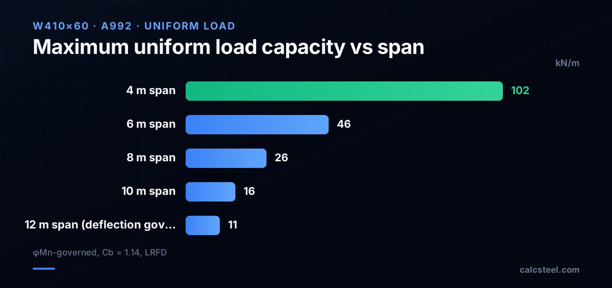
Every structural engineer hears this question: how much weight can my beam hold? The honest answer is never one number — it is five separate checks, any of which can govern. A W410×60 carrying a 4-metre span handles 102 kN/m in flexure, but at 12 metres the same beam is limited to 11 kN/m by deflection. Here is how each check works, why deflection often governs, and how to run all five in CalcSteel in seconds.
Key takeaways
- A beam's load capacity is not a single number — it is the minimum of five checks: flexure (yielding and LTB), shear, deflection, web crippling, and sometimes vibration.
- For spans above 8–10 m, deflection (L/360 or L/240) almost always governs before the strength limit is reached.
- LRFD uses factored loads (1.2D + 1.6L) for strength checks but unfactored (service) loads for deflection — do not mix them.
- CalcSteel runs all five checks simultaneously and shows which one governs, so you never accidentally ignore the controlling limit state.
How much weight can a steel beam support?
There is no universal table that says "a W410×60 holds X kN." The maximum load depends on at least five factors: span length, unbraced length of the compression flange, support conditions (simply supported vs. continuous vs. cantilever), load type (uniform vs. concentrated), and the limit state that governs (flexure, shear, deflection, web crippling, or vibration).
A short beam (say 3 m) with a compact section and continuous lateral bracing will be limited by flexural yielding: Mn = Fy × Zx. The same beam at 12 m will almost certainly be limited by deflection: the L/360 serviceability criterion is reached long before the steel yields. Between these extremes, lateral torsional buckling may reduce the flexural capacity, and for short, deep beams with heavy point loads, shear or web crippling can govern.
This is why the question "how much can it hold?" requires a design check, not a lookup. Software like CalcSteel runs all five checks in parallel and highlights the governing one — so you never accidentally size a beam for strength when deflection was the real bottleneck.
What determines the load capacity of a steel beam?
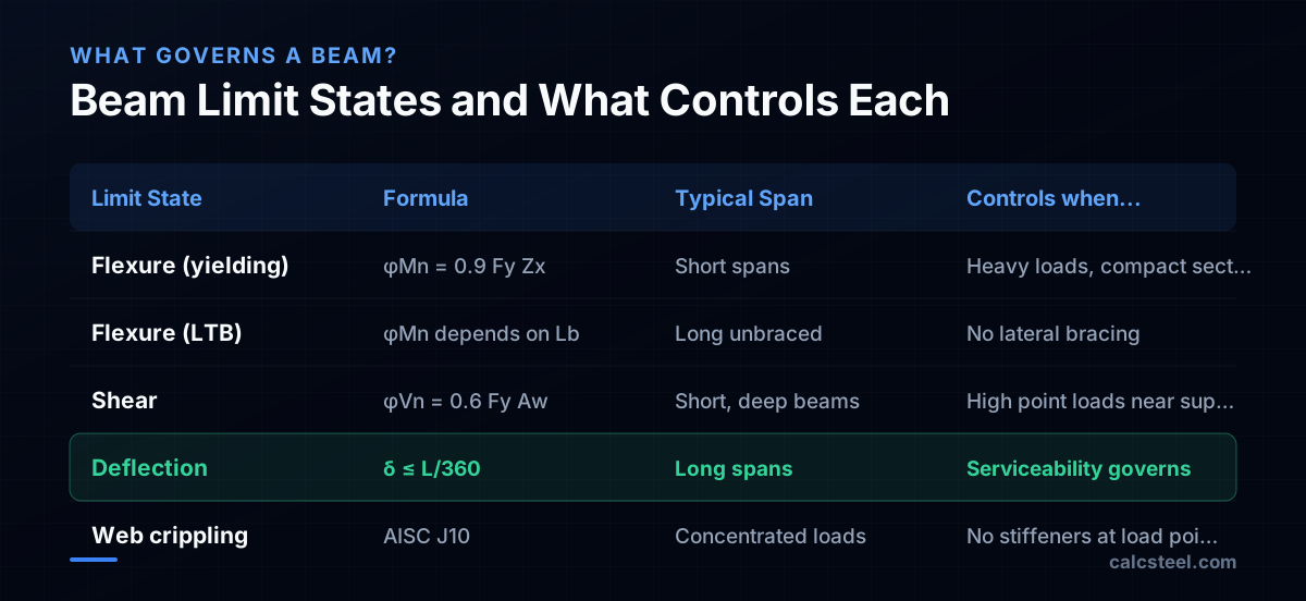
Five limit states compete to control a beam's capacity. The beam is only as strong as the weakest one:
- Flexural yielding (strength). The cross-section reaches its plastic moment Mp = Fy × Zx. This governs when the beam is compact, fully braced, and the span is short enough that deflection is not an issue. For a W410×60 in A992 steel: Mp = 345 × 1 190 × 10³/10⁶ = 411 kN·m.
- Lateral torsional buckling (LTB). If the compression flange is unbraced for too long, the beam twists sideways before reaching Mp. The capacity depends on the unbraced length Lb and the moment gradient factor Cb. See our detailed LTB guide.
- Shear. The web resists shear: Vn = 0.6 Fy Aw Cv. Shear rarely governs except for short, deep beams with heavy concentrated loads near the supports (transfer girders, crane runways).
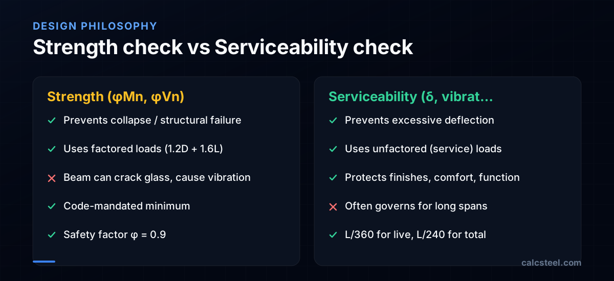
- Deflection (serviceability). Even if the beam is strong enough, excessive deflection cracks partitions, pops floor tiles, and makes the floor feel bouncy. Codes limit live-load deflection to L/360 and total deflection to L/240. For long spans (>8 m), this is almost always the controlling check.
- Web crippling and local effects. Concentrated loads applied to the top flange can crush or buckle the web locally. AISC 360 Section J10 covers web local yielding and web crippling — usually addressed with bearing stiffeners rather than upsizing the beam.
How to calculate the maximum load on a steel beam?
For a simply supported beam with a uniform load w (kN/m) over a span L, the maximum moment is Mmax = wL²/8 and the maximum shear is Vmax = wL/2. To find the maximum w that the beam can carry, you invert the flexural formula:
wmax,flexure = 8 × φMn / L²
For a W410×60 (φMn = 370 kN·m at full plastic capacity, Lb ≤ Lp) over a 4 m span:
wmax = 8 × 370 / 4² = 2 960 / 16 = 185 kN/m (factored).
But you need to convert to service loads for a practical answer. With a typical 1.2D + 1.6L combination and D/L ≈ 1, the service load is roughly 185/1.4 ≈ 132 kN/m.
Now check deflection. For a simply supported beam with uniform load: δmax = 5wL⁴/(384EI). Setting δ = L/360 and solving for w (service load):
wmax,deflection = 384 × E × I × (1/360) / (5 × L³)
For the W410×60 (Ix = 216 × 10⁶ mm⁴) at 4 m: wmax,defl = 384 × 200 000 × 216 × 10⁶ / (360 × 5 × 4 000³) = very large — deflection does not govern at this short span.
But at 12 m: the deflection limit gives w ≈ 11 kN/m (service), while flexure still allows ~20 kN/m (service). Deflection governs.
What is the difference between ASD and LRFD for beam design?
AISC 360 offers two design philosophies, and they give nearly identical results for typical beams:
LRFD (Load and Resistance Factor Design) multiplies loads up and resistance down: U = 1.2D + 1.6L must be ≤ φRn (with φ = 0.9 for flexure and 1.0 for shear). The factored-load approach captures the idea that live loads are less predictable than dead loads.
ASD (Allowable Stress Design) divides the resistance by a safety factor: D + L must be ≤ Rn/Ω (with Ω = 1.67 for flexure). This is the older method (AISC used it exclusively until 1986) and is still popular in practice because it uses unfactored loads — easier to interpret physically.
The ratio between the two is built into the factors: φ × Ω = 0.9 × 1.67 = 1.5. For a dead-to-live ratio of about 1:1, the two methods give the same beam size. They diverge when the load mix is unusual (very high live load or very high dead load).
For serviceability (deflection), both methods use unfactored service loads — there is no difference. This is critical: the deflection check sees the same loads in both LRFD and ASD. Since deflection often governs long-span beams, the choice between LRFD and ASD has less practical impact than many engineers expect.
CalcSteel supports both LRFD and ASD. You choose the method in the project settings, and all design checks switch accordingly. The deflection check always uses service loads regardless of the method selected.
How does beam span affect load capacity?
Span is the single most powerful variable. For a simply supported beam with uniform load, the maximum moment scales with L² and the maximum deflection scales with L⁴. Doubling the span quadruples the moment and increases deflection sixteen-fold.
This is why long-span beams are almost always governed by deflection, not strength. The L⁴ term in the deflection formula (δ = 5wL⁴/384EI) overwhelms everything else. A W410×60 that is perfectly adequate for a 6 m span may need to be upsized to a W530×82 at 10 m — not because the smaller beam cannot resist the moment, but because it deflects too much.
Practical span-to-depth guidelines (rules of thumb for preliminary sizing):
- Floor beams (L/360 deflection): depth ≈ L/20 to L/24. A 10 m beam needs d ≈ 420–500 mm.
- Roof beams (L/240 deflection): depth ≈ L/24 to L/30. A 10 m roof beam can be shallower (d ≈ 330–420 mm) because the deflection limit is more relaxed.
- Cantilevers: depth ≈ L/8 to L/10. Much deeper because the deflection formula for cantilevers is δ = wL⁴/8EI — the coefficient is 48× worse than a simply supported beam.
These ratios let you pick a starting section for detailed analysis. In CalcSteel, you can run a parametric sweep: try 3–4 profile sizes and instantly compare their utilisation ratios and deflections.

Which steel beam size do I need for my span?
This is the question behind the question. Engineers and architects want a quick table, and for preliminary design, here is a reasonable starting point for floor beams (simply supported, live load 3–5 kN/m², tributary width 3 m, L/360 deflection limit):
- 4 m span: W200×27 or W250×25
- 6 m span: W310×33 or W360×33
- 8 m span: W410×46 or W410×53
- 10 m span: W460×60 or W530×66
- 12 m span: W530×82 or W610×82
These are rough starting points — the actual required section depends on the specific loading, bracing, support conditions, and deflection criteria. A beam in a composite floor system (steel + concrete slab) can be 20–30% lighter because the slab increases the effective moment of inertia.
The reliable approach is to use software: enter the span, loading, and boundary conditions, and let the tool size the section. CalcSteel's profile browser shows all available sections sorted by weight, with the utilisation ratio for each, so you can pick the lightest section that passes all checks.
For existing structures, the question is inverted: what load can the existing beam carry? In that case, you know the section and span, and you solve for the maximum permissible uniform load. The step-by-step calculation below shows exactly how to do this.

How to check beam capacity in CalcSteel?
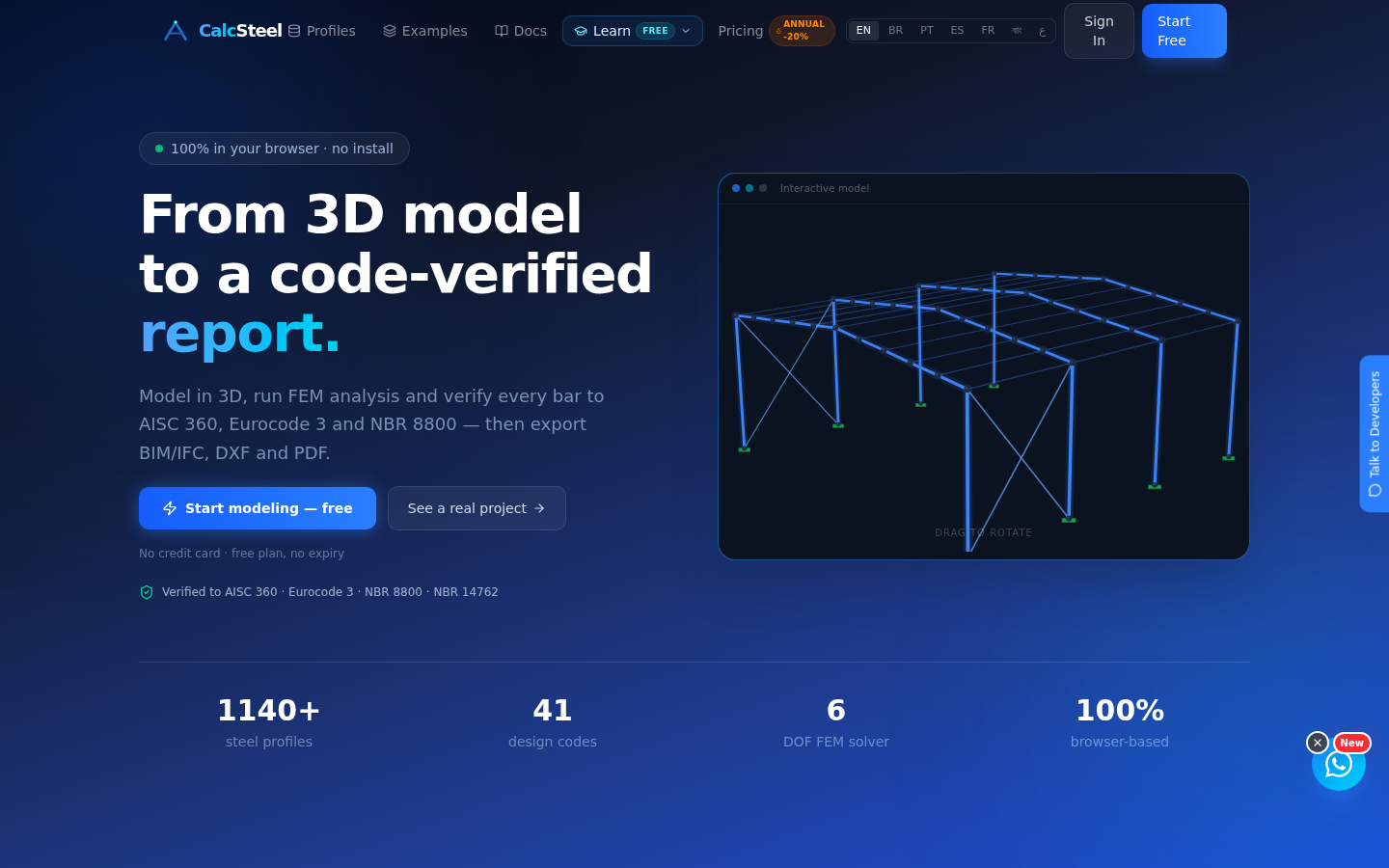
CalcSteel runs all five limit-state checks in one pass. Here is the workflow:
Step 1 — Model the beam. Draw a member between two supports (pin-pin for simply supported, or pin-fixed for propped cantilever). Select the profile from CalcSteel's database — type the designation (e.g., W410×60) and the section properties are loaded automatically.
Step 2 — Apply loads. Add a uniform distributed load (kN/m) for dead and live load cases separately. CalcSteel builds the standard AISC load combinations (1.4D, 1.2D+1.6L, etc.) automatically.
Step 3 — Set the unbraced length. The default is the full member length. If the compression flange is braced at intermediate points (by floor joists, for example), enter the actual unbraced length Lb. The Cb factor is computed automatically from the moment diagram.
Step 4 — Run analysis and read results. CalcSteel solves the frame, computes internal forces, and runs the AISC 360 design verification. Open the Design Verification panel to see:
- Flexural check: Mu/φMn — the utilisation ratio for bending.
- Shear check: Vu/φVn — the utilisation ratio for shear.
- Deflection check: δmax vs. the allowable limit (L/360, L/240, or custom).
- Governing check: CalcSteel highlights which limit state controls — so you know immediately whether to focus on strength or serviceability.
You can toggle between profiles and see the ratios update in real time. This is the fastest way to find the lightest beam that passes all checks.
Steel beam load capacity calculation step by step
Let us calculate the maximum uniformly distributed load that a W410×60 (A992, Fy = 345 MPa) can carry over an 8 m simply supported span with full lateral bracing (Lb = 0).
Step 1 — Plastic moment. Mp = Fy × Zx = 345 × 1 190 × 10³ / 10⁶ = 411 kN·m. With full bracing, Mn = Mp and φMn = 0.9 × 411 = 370 kN·m.
Step 2 — Maximum factored load (flexure). For a simply supported beam: Mmax = wL²/8. Solving for w: wu = 8 × φMn / L² = 8 × 370 / 8² = 46.2 kN/m (factored).
Step 3 — Convert to service load. Assuming D/L ≈ 1 and using 1.2D + 1.6L: the average load factor is ~1.4, so wservice ≈ 46.2 / 1.4 = 33 kN/m.
Step 4 — Check shear. Vmax = wuL/2 = 46.2 × 8 / 2 = 185 kN. Shear capacity: φVn = 1.0 × 0.6 × 345 × (407 × 7.7) / 1 000 = 649 kN. Ratio = 185/649 = 0.28. Shear does not govern.
Step 5 — Check deflection. δ = 5wL⁴/(384EI) with service live load wL ≈ 16.5 kN/m = 16.5 N/mm. δ = 5 × 16.5 × 8 000⁴ / (384 × 200 000 × 216 × 10⁶) = 20.1 mm. Allowable: L/360 = 8 000/360 = 22.2 mm. Ratio = 20.1/22.2 = 0.91. Deflection is close to governing!
At 8 m, flexure and deflection are neck-and-neck. At 10 m, deflection would govern definitively. In CalcSteel, you would see the deflection ratio highlighted in yellow — a warning that you are within 10% of the limit.
Sources
- 1.AISC 360-22 Specification for Structural Steel Buildings
- 2.AISC Steel Construction Manual, 16th Edition — Beam Design Tables
- 3.NBR 8800:2024 — Projeto de estruturas de aço (Flexão e Estado Limite de Serviço)
- 4.Eurocode 3: Design of steel structures (EN 1993-1-1)
- 5.SkyCiv: Steel Beam Calculator — Free Online Tool
- 6.Engineering ToolBox: Beam Deflection Formulas
- 7.r/StructuralEngineering: How do I size a steel beam? (Reddit)
- 8.Steel Beam Design Example — University of Michigan CEE
Try CalcSteel for free
Model, analyze and design steel structures in your browser. No install, no signup.
Open the 3D editor