Statically Indeterminate Structures: Why the Hand Method Stops and the Matrix Method Starts

A statically indeterminate structure has more unknown forces than statics can solve on its own, so equilibrium is no longer enough and you have to bring in how the structure deforms. This is where the classic hand methods live, the force method, slope-deflection, moment distribution, and it is also where they run out of road. Here is what indeterminacy is, how to count it, how the hand methods solve it, exactly where they stop, and how the matrix (direct stiffness) method that powers every modern solver, including CalcSteel's, picks up. Three worked cases are computed by the real FEM engine and match closed-form theory to three decimals.
Key takeaways
- A structure is statically indeterminate when its unknown reactions and internal forces outnumber the equilibrium equations (three in a plane). The surplus is the degree of static indeterminacy (DSI), and each unit of it is one redundant you cannot find from statics alone.
- Count it as a subtraction: for a plane beam DSI = r − 3; for a plane frame DSI = (3m + r) − 3n. A propped cantilever and a two-span continuous beam are both DSI 1; a fixed-base portal frame is DSI 3.
- Hand methods work by adding compatibility (deformation) conditions to equilibrium. The force method solves one equation per redundant; slope-deflection and moment distribution solve for joint displacements instead. All of them scale badly: the work grows with every redundant or joint you add.
- Worked and engine-checked to three decimals: a propped cantilever (w = 24 kN/m, L = 6 m) gives a fixed-end moment of −108 kN·m (wL²/8) and a span moment of +60.75 kN·m (9wL²/128); a two-span continuous beam draws −108 kN·m over the interior support; the force-method redundant is exactly the prop reaction, 3wL/8 = 54 kN.
- The matrix (direct stiffness) method organizes the same physics as K d = F, assembled member by member and solved by a computer, so it has no practical ceiling. It is the backbone of FEM and it is what CalcSteel's engine runs; the portal frame here (DSI 3, gravity plus wind) has no closed form, and the engine returns the full sidesway solution.
The line where statics runs out
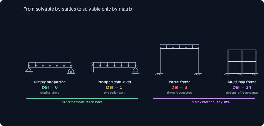
Take a simply supported beam, one pin, one roller, and a uniform load. You can find both reactions with nothing but a sheet of paper and the three equations of statics: sum of horizontal forces, sum of vertical forces, sum of moments, each equal to zero. Every internal shear and moment follows from those reactions. The beam is statically determinate: the number of unknowns equals the number of equilibrium equations, and equilibrium alone tells you everything.
Now weld that same beam's left end into a wall, or drop a third support under a long beam, or bend two columns up to carry it as a frame. You have added a reaction, but you have not added an equation, statics still gives you only three in a plane. The structure now has more unknowns than equilibrium can solve. It is statically indeterminate, also called hyperstatic, and the extra forces cannot be found from statics at all. That is not a defect; it is the normal condition of almost every real building. This article is about what changes when you cross that line: what indeterminacy is, how to count it, how engineers have solved it by hand for over a century, precisely where those hand methods stop being practical, and how the matrix method that starts there became the engine inside every structural solver.
Determinate versus indeterminate, in one idea
The whole distinction rests on a count. In two dimensions a rigid body has exactly three independent equilibrium equations, so it can resolve three unknown force quantities and no more. Line up your unknowns, the support reactions plus any internal force redundancies, against those equations:
- Unknowns fewer than equations: the structure is a mechanism, it moves, it is unstable. Not a structure at all.
- Unknowns equal to equations: statically determinate. Equilibrium solves it exactly, and the internal forces do not depend on the stiffness of the members, only on geometry and load.
- Unknowns more than equations: statically indeterminate. Equilibrium is necessary but no longer sufficient, and the missing equations have to come from somewhere else.
That somewhere else is compatibility: the requirement that the structure's deflections and rotations fit together, that a continuous beam stays continuous over its middle support, that a fixed end truly does not rotate. Compatibility conditions are extra equations, and they are written in terms of how the structure deforms. The instant a structure is indeterminate, its internal forces start to depend on the relative stiffness of its members, on E, on I, on section and length, because stiffness is what decides how the redundant force is shared. That single fact, that indeterminate forces depend on stiffness while determinate forces do not, is the root of everything that follows.
How to count the degree of indeterminacy
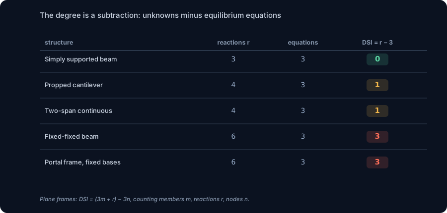
The degree of static indeterminacy is a plain subtraction, unknowns minus available equations. For a plane beam or a simple structure whose only unknowns are reactions:
DSI = r − 3 − c
where r is the number of reaction components, 3 is the plane equilibrium equations, and c is the number of condition equations released by internal hinges (an internal hinge adds one equation, that the moment there is zero). A pinned support gives two reaction components, a roller one, a fixed support three.
For a rigid plane frame, count members and joints too, because each rigidly connected member carries its own three internal force quantities:
DSI = (3m + r) − 3n − c
with m members, r reaction components, n nodes (joints, including supports), and c releases. Run it on the cases in the table. A propped cantilever is a fixed support (3) plus a roller (1), so r = 4 and DSI = 1. A two-span continuous beam on a pin and two rollers also has r = 4 and DSI = 1. A portal frame on two fixed bases has m = 3, r = 6, n = 4, so DSI = 9 + 6 − 12 = 3. Each unit of DSI is one redundant, one force you get to choose freely before compatibility pins it down.
Why we build indeterminate structures on purpose
If indeterminacy makes the analysis harder, why is nearly every real frame indeterminate? Because the same continuity that complicates the maths buys three things you want.
Stiffness. Continuity and fixity fight deflection hard. A fixed-fixed beam under a uniform load deflects only one fifth as much as the same beam simply supported (wL⁴/384EI against 5wL⁴/384EI). For serviceability-governed members, which is most floor beams, that is the difference between a section that works and one that does not.
Smaller peak moments. Fixity spreads the bending around. That fixed-fixed beam peaks at wL²/12 at its ends instead of wL²/8 at midspan, a third less moment for the same span and load. Continuity over a support does the same trick, trading a smaller field moment for a hogging moment at the support.
Redundancy, which is to say safety. The literal meaning of a redundant is an alternate load path. If one section of an indeterminate structure is overloaded and yields, the structure does not necessarily fall; the moment redistributes to the parts that still have capacity, and it keeps standing while it warns you. A determinate structure has no spare path: lose one member or form one hinge and it becomes a mechanism. This is why codes reward redundancy and why progressive-collapse thinking leans on it. Indeterminacy is not a cost you tolerate; it is a property you design in.
The first hand method: the force (flexibility) method
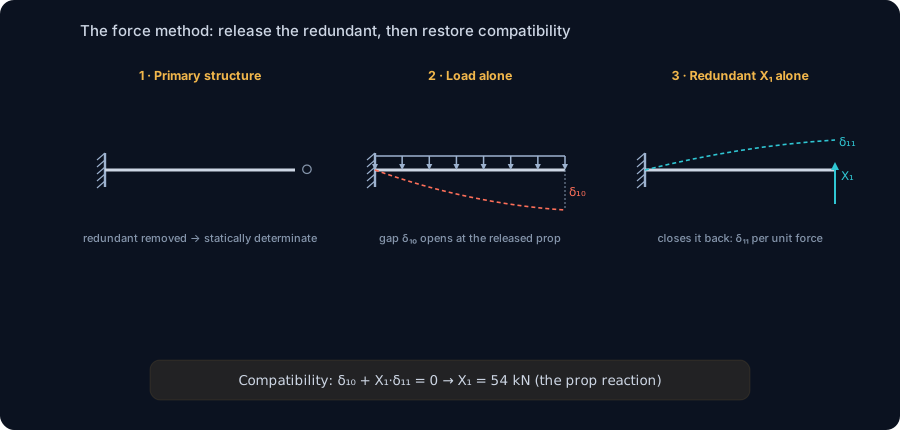
The oldest and most intuitive way to solve an indeterminate structure is the force method, also called the flexibility method or the method of consistent deformations. The idea is disarmingly simple. You have too many unknown forces, so you pick DSI of them, the redundants, and imagine removing them. What is left, the primary structure, is determinate, so statics solves it outright.
Of course, removing a support lets the structure deform in a way the real one never would: a released prop lets the beam sag where the prop should have held it. So you compute that illegal deflection at the release under the applied load, call it δ₁₀. Then you put the redundant back as an unknown force X₁ and compute the deflection it produces per unit, δ₁₁. The real structure does not deflect at the support at all, so the two must cancel. That is the compatibility equation:
δ₁₀ + X₁·δ₁₁ = 0
One redundant, one equation, one unknown force recovered. With more redundants it becomes a small system, [δ]{X} = −{δ₀}, where [δ] is the flexibility matrix, one row and column per redundant. Solve it, add the redundants back, and finish with statics. The force method is the cleanest possible picture of what indeterminacy is: exactly DSI conditions, each one a geometric statement that the structure fits together.
The other hand methods: slope-deflection and moment distribution
The force method treats forces as the unknowns. The rival family, the displacement (stiffness) methods, treats the joint movements as the unknowns instead, and for real frames it usually wins, because a frame typically has fewer free joint rotations than it has redundant forces.
Slope-deflection (1915) writes every member's end moments as a formula in the rotations of its two ends and any sway between them, then enforces moment equilibrium at each joint. That gives one equation per unknown rotation, a system you solve simultaneously. Moment distribution, Hardy Cross's 1930 method, was the breakthrough that put frame analysis in the hands of anyone with a slide rule: it locks all the joints, computes fixed-end moments, then releases the joints one at a time and lets the out-of-balance moment distribute to the connected members by their relative stiffness, iterating until the leftovers are negligible. No simultaneous equations at all, just disciplined bookkeeping, and it converges fast for continuous beams and braced frames. Clapeyron's three-moment theorem (1857) is the specialist tool for continuous beams, relating the moments over three consecutive supports in a single equation per interior support.
These methods are genuinely powerful, and every structural engineer should be able to run moment distribution on a two-span beam or a single-bay frame. But look at what each one costs as the structure grows, because that cost is the whole reason the matrix method exists.
Worked case 1: a propped cantilever, by hand and by engine
Take the canonical first indeterminate structure: a propped cantilever, fixed at one end and propped on a roller at the other, spanning L = 6 m under a uniform load w = 24 kN/m. It is DSI 1, so the force method needs exactly one compatibility equation.
Choose the prop reaction as the redundant X₁ and release it. The primary structure is a plain cantilever fixed at the left. Under the load w, the free (propped) end of a cantilever sags by δ₁₀ = wL⁴/8EI. Under a unit upward force at that end it lifts by δ₁₁ = L³/3EI. The real prop holds the end at zero, so:
X₁ = −δ₁₀ / δ₁₁ = (wL⁴/8EI) / (L³/3EI) = 3wL/8 = 54 kN
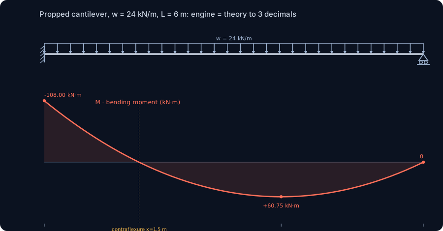
Notice EI cancels: for a single prismatic member the redundant does not depend on stiffness after all, so the answer is exact and clean. Now finish with statics. The fixed-end reaction is wL − X₁ = 144 − 54 = 90 kN (that is 5wL/8), and the fixed-end moment is wL²/2 − X₁·L = 432 − 324 = 108 kN·m of hogging, exactly wL²/8. The span moment peaks at x = 5L/8 = 3.75 m with a value of 9wL²/128 = 60.75 kN·m, and the bending moment passes through zero (the point of contraflexure) at x = L/4 = 1.5 m.
Now the check. We built the same beam in the CalcSteel FEM engine, the real shipping solver, and it returns R at the fixed end = 90.000 kN, R at the prop = 54.000 kN, the fixed-end moment = −108.000 kN·m, and the span peak = +60.750 kN·m at x = 3.750 m. Every number matches the hand solution to three decimals, which is the point: for one redundant the hand method and the engine are the same answer, and the engine simply did the compatibility for you.
Worked case 2: a two-span continuous beam
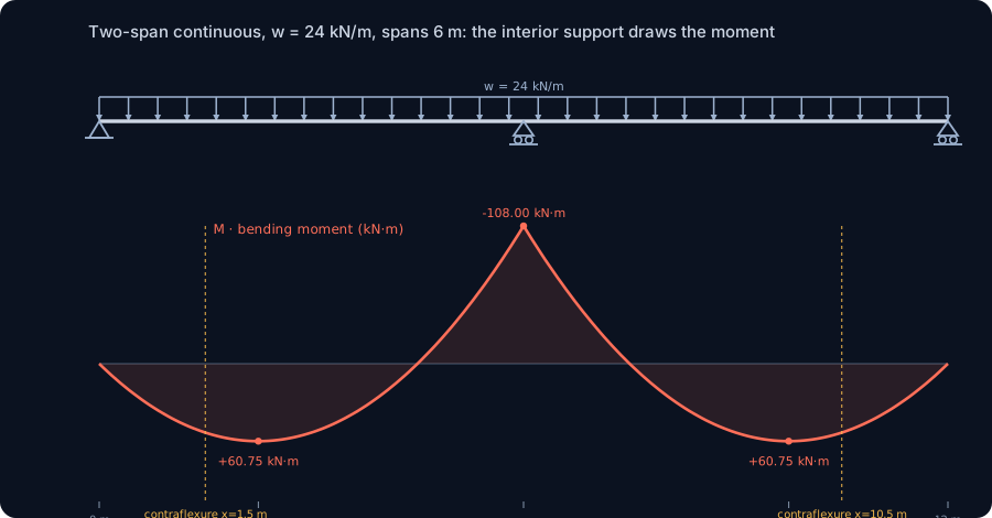
Add a support instead of a fixity and you get the other everyday DSI-1 case, a two-span continuous beam: a pin, an interior roller, and an end roller, two spans of L = 6 m each, the same w = 24 kN/m throughout. Here the natural hand tool is Clapeyron's three-moment theorem, which for two equal spans with a uniform load gives the interior support moment directly:
MB = −wL²/8 = −108 kN·m
The interior support is doing exactly what continuity buys: it draws a hogging moment out of the beam and, in exchange, holds the mid-span moments down to 9wL²/128 = 60.75 kN·m, the very same field moment as the propped cantilever, which is no coincidence, since each span of this beam behaves like a propped cantilever with the interior support playing the role of the near-fixity. Statics then gives the reactions: 3wL/8 = 54 kN at each end and 10wL/8 = 1.25wL = 180 kN at the interior support, which carries the lion's share.
The engine agrees down the line: end reactions 54.000 kN, interior reaction 180.000 kN, interior support moment −108.000 kN·m, span peaks +60.750 kN·m. Two different indeterminate structures, one solved by the force method and one by the three-moment equation, and in both the shipping FEM solver reproduces the classical result exactly. That is the reassurance the hand methods give you: at DSI 1 you can still hold the whole solution in your head, and the software is auditable against it.
Where the hand method stops
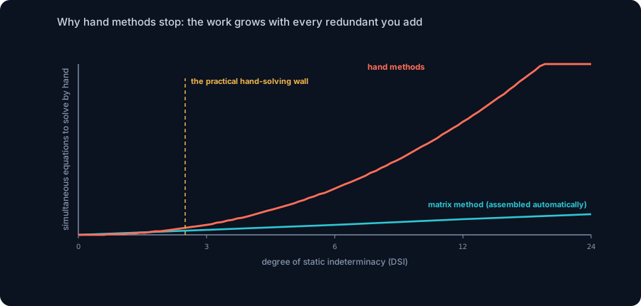
At DSI 1 the hand method is a pleasure. The trouble is that the effort does not grow gently. In the force method the flexibility matrix is DSI by DSI, so a structure with three redundants needs a 3 by 3 system, six needs 6 by 6, and every one of those coefficients δij is itself a separate deflection calculation you have to work out and get right. In the displacement methods the unknown count is the number of free joint displacements, which climbs just as fast in a real building, and slope-deflection turns them into a simultaneous system while moment distribution's iteration slows and multiplies once sidesway enters, because a frame free to lean sideways needs extra sway cycles layered on top of the joint balancing.
So the wall is real, and it arrives early. A single-bay portal frame (DSI 3) is already a serious hand calculation, an afternoon of slope-deflection with a sway equation, or moment distribution done twice. A two-storey, two-bay frame is beyond what anyone sane does by hand. A full building, a grid, anything in three dimensions, is simply not a hand problem, and there is no clever method waiting to rescue it, because the difficulty is not the technique, it is the sheer number of coupled unknowns. The hand methods did not fail; they hit the size of the linear system a human can carry.
Where the matrix method starts
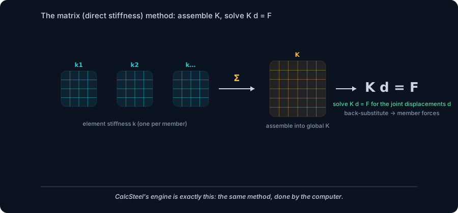
The matrix method does not out-clever the hand methods; it out-organizes them. It is the displacement method, the same joint-movement-as-unknown idea behind slope-deflection, written in a form a computer can assemble mechanically and solve at any scale. It is called the direct stiffness method, and it is the backbone of finite element analysis.
The recipe never changes with size. Each member gets a small element stiffness matrix k that relates the forces at its two ends to the displacements at its two ends, pure geometry and EA, EI, L. Each of those is rotated into global axes and added into a global stiffness matrix K at the rows and columns of the joints it connects; overlapping members simply sum where they share a joint. Apply the loads as a vector F and the boundary conditions, and the entire structure is now one linear system:
K d = F
Solve it once for the joint displacements d, then back-substitute through each element's k to recover every member's shears and moments. There is no separate treatment for determinate or indeterminate, no choosing redundants, no sway equation, no iteration; indeterminacy is handled implicitly the moment the stiffnesses are assembled, because K already encodes how every member shares load with its neighbours. Doubling the size of the frame just makes K bigger, and a computer does not mind. This is exactly what CalcSteel's engine runs, the same method, at machine precision; the three worked cases above were solved by it, and so is the portal frame next.
See it yourself: solve an indeterminate beam live
The calculator below is the direct stiffness method, running in your browser on the same FEM engine as the worked cases. Build a propped cantilever or a continuous beam, fix an end or add a third support, put a uniform load on it, and read the reactions and the bending moment diagram straight out of K d = F. Try it on the DSI-1 cases above and watch the numbers land on 90, 54, −108 and 60.75 without you ever choosing a redundant.
It is free, no login for the analysis, and it never stops at DSI 1, add supports and members until you have a structure no hand method could touch, and it solves in the same instant.
Max moment
45 kN·m
Max shear
30 kN
Max deflection
10.55 mm
= L/569
Bending stress σ
84.4 MPa
σ = M/Sx
Utilization
44.0%
NBR 8800 · δ ≤ L/250
Geometry & supports
Section
Ix 7999 cm⁴ · Sx 533 cm³ · 42.2 kg/m
Point loads (↓ positive)
None — add as many as you need.
Distributed loads (uniform or trapezoidal)
Model sketch
Diagrams — free PNG / SVG / CSV export, no watermark
Step-by-step — the calculation memory of YOUR beam
IPE 300 · L = 6 m · fy = 250 MPa
1. Reactions (equilibrium of the solved FEM model)
ΣFy = 0 · ΣM = 0
R_A = 30 kN · R_B = 30 kN
2. Peak shear (read from the SFD)
Vmax = |V(x)|max
Vmax = -30 kN @ x = 6 m
3. Peak moment (read from the BMD)
Mmax = |M(x)|max
Mmax = 45 kN·m @ x = 3 m
4. Peak deflection
EI = 15998 kN·m² (E = 200 GPa)
δmax = 10.55 mm @ x = 3 m = L/569
5. Elastic bending stress
σ = Mmax / Sx = 45.00 × 10³ / 533.3
σ = 84.4 MPa
6. Bending check — both codes, side by side
NBR 8800: σ ≤ fy/1.10 = 227.3 MPa · AISC 360: σ ≤ 0.90·fy = 225 MPa
NBR 37.1% PASS · AISC 37.5% PASS
7. Deflection check (serviceability — code-independent)
δ ≤ L/250 = 24 mm
10.55 mm / 24 mm = 44.0% PASS
Recomputed live from the current inputs by the direct-stiffness FEM engine — change any load and every step updates. Reproduce it by hand with the formulas in the sections below.
Lightest catalog profiles that pass (974 flexural candidates · NBR 8800)
| Profile | Std | Weight | Total steel | σ util | δ util | |
|---|---|---|---|---|---|---|
| W310x21 | AISC | 21 kg/m | 126 kg | 83% | 98% | |
| VS 300x23 | BR | 22.6 kg/m | 136 kg | 71% | 84% | |
| U 300x90x6.3 | BR | 23.1 kg/m | 139 kg | 82% | 98% | |
| U 300x100x6.3 | BR | 24.1 kg/m | 145 kg | 77% | 91% | |
| VS 250x25 | BR | 24.6 kg/m | 148 kg | 70% | 100% |
Elastic bending (σ = M/Sx vs fy/γa1, γa1 = 1.10 — NBR 8800) + deflection screening of the full flexural catalog. Lateral-torsional buckling, shear and local buckling are NOT checked here — run the full NBR 8800 / AISC 360 verification in the 3D editor.
Worked case 3: a portal frame, where only the matrix method answers
Finish with the case that has no formula in any handbook: a portal frame, an 8 m beam on two 5 m columns fixed at their bases, carrying a gravity load of 20 kN/m on the beam and a 15 kN horizontal wind push at the top. It is DSI 3, and the wind makes it lean, so all three redundants couple through sidesway. There is no closed form; this is a matrix-only problem.
The engine returns the whole solution at once. The two column bases, though the frame and its gravity load are perfectly symmetric, carry very different fixing moments, 4.25 kN·m on the windward base and 34.45 kN·m on the leeward one. The two beam-to-column knees are just as lopsided, 12.07 kN·m windward against 48.37 kN·m leeward, and the beam sags to a peak of 129.8 kN·m at mid-span. The vertical reactions split 75.46 kN and 84.54 kN as the frame leans downwind, and the 15 kN of wind is shared 1.56 kN and 16.56 kN between the bases. Every one of those asymmetries is the sidesway talking, and no single hand equation produces them; you would need slope-deflection with a sway unknown, carefully, to get even close.
The sanity checks still close by hand, which is how you trust the solver: the vertical reactions sum to 75.46 + 84.54 = 160 kN, exactly the 20 kN/m over 8 m of gravity, and the horizontal reactions sum to 1.56 − 16.56 = −15 kN, exactly balancing the wind. Equilibrium is always necessary; here the matrix method supplied the compatibility that equilibrium alone could never reach.
Common mistakes and FAQ
Confusing indeterminate with unstable. Both have a mismatch between unknowns and equations, but in opposite directions. Too few unknowns (or badly arranged ones) is a mechanism, it moves. Too many is indeterminate, it is stiffer than statics can describe. Always check stability and arrangement, not just the count; three reactions all parallel or all through one point is unstable even though the number looks right.
Thinking indeterminate forces are independent of the section. They are not. The moment a structure is indeterminate, the internal forces depend on relative stiffness, on E and I and member length. Change a section and the moments redistribute. Determinate forces do not care about stiffness; indeterminate ones always do.
Forgetting condition equations from internal hinges. An internal hinge releases a moment and adds one equation, dropping the DSI by one. A beam that looks over-supported can be determinate, or even a mechanism, once its hinges are counted. Do not read DSI off the supports alone.
Is a statically indeterminate structure stronger? Usually stiffer and more redundant, not automatically stronger in the ultimate sense, but the redundancy gives alternate load paths and lets moments redistribute before collapse, which is a real safety margin.
Do I still need the hand methods if the software solves everything? Yes. You cannot audit an answer you cannot estimate. Moment distribution on a two-span beam or a mental wL²/8 keeps the solver honest and catches the modelling error, the wrong support, the missing release, that turns a right method into a wrong number.
What is the difference between the stiffness method and finite elements? None, in spirit. The direct stiffness method for frames is finite element analysis with one beam element per member; FEM is the same assembly of K d = F generalized to plates, shells and solids.
Key takeaways
Indeterminacy is the normal state of real structures, and crossing into it changes both the maths and the tool you reach for.
- A structure is statically indeterminate when unknowns exceed equilibrium equations; the surplus is the degree of static indeterminacy, DSI = r − 3 for a plane beam, (3m + r) − 3n for a plane frame.
- Beyond equilibrium you need compatibility, and from that point the internal forces depend on member stiffness, on E, I and L, not on geometry alone.
- The hand methods add exactly the missing conditions: the force method solves one equation per redundant; slope-deflection and moment distribution solve for joint movements. All of them scale badly and hit a practical wall within a few degrees of indeterminacy.
- Verified against the engine to three decimals: a propped cantilever gives −108 kN·m (wL²/8) fixed and +60.75 kN·m (9wL²/128) in the span; a two-span continuous beam draws −108 kN·m over the interior support; the force-method redundant is the prop reaction, 3wL/8 = 54 kN.
- The matrix (direct stiffness) method writes the same physics as K d = F, assembled member by member and solved by computer, with no ceiling. It runs CalcSteel's engine, and it is the only practical way to solve a wind-loaded portal frame (DSI 3) or anything larger.
Sources
- 1.Hibbeler, Structural Analysis (determinacy, stability, the force and displacement methods)
- 2.Kassimali, Matrix Analysis of Structures (the direct stiffness method)
- 3.McGuire, Gallagher and Ziemian, Matrix Structural Analysis
- 4.Hardy Cross, Analysis of Continuous Frames by Distributing Fixed-End Moments, ASCE Transactions (1930)
- 5.AISC 360, Specification for Structural Steel Buildings (analysis requirements)
- 6.ABNT NBR 8800, Projeto de estruturas de aco e de estruturas mistas de aco e concreto
Try CalcSteel for free
Model, analyze and design steel structures in your browser. No install, no signup.
Open the 3D editor