Serviceability: Deflection & Vibration Limits
Learn how to check steel beams for deflection limits (L/360, L/240) and floor vibration criteria per AISC Design Guide 11. Covers formulas, examples, and when stiffness governs.
What is serviceability in structural steel design?
Serviceability is the set of performance criteria that ensure a structure is comfortable, functional, and durable under everyday (service) loads — not just safe from collapse. A beam can be perfectly adequate for strength but fail serviceability if it deflects too much or vibrates annoyingly.
The main serviceability checks for steel structures are:
- Deflection — Vertical sag under gravity loads. Excessive deflection cracks partitions, causes ponding on roofs, and looks alarming to occupants.
- Vibration — Dynamic response to walking, running, or rhythmic activities. Annoying vibration does not endanger the structure but makes the floor feel unsafe.
- Drift — Lateral sway under wind or seismic loads. Excessive drift damages cladding and causes motion sickness in tall buildings.
Serviceability checks use unfactored (service-level) loads, not the factored loads used for strength design. The building must work under normal conditions, not just under extreme events.
What are the deflection limits for steel beams?
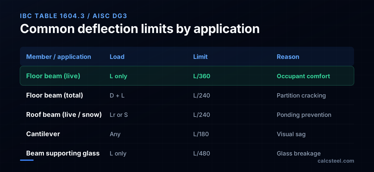
Deflection limits are expressed as a fraction of the span length L. The most common limits per IBC Table 1604.3 and AISC practice are:
Floor beams - Live load only: L/360 (the universal default for occupant comfort) - Total load (D + L): L/240 (to prevent cracking of plaster or drywall partitions) - Supporting brittle finishes (tile, glass): L/480
Roof beams - Live/snow load: L/240 - Total load: L/180 - Ponding-sensitive roofs: L/360 (to prevent progressive accumulation of water)
Cantilevers - Multiply the above limits by 2 (cantilever deflection is inherently larger) - Example: live load limit = L/180 (half of L/360)
Where the limits come from
The L/360 limit was established empirically — it corresponds to a visual sag that most people can detect. At L/240, cracks may form in gypsum board partitions. At L/480, brittle materials like glass or ceramic tile begin to crack.
These limits are NOT code requirements in the strictest sense — IBC Table 1604.3 provides them as recommended limits. The engineer can use different limits with justification.
How do you calculate beam deflection step by step?
Beam deflection is calculated using the elastic deflection formulas or the direct stiffness method. The key formula for a simply supported beam is:
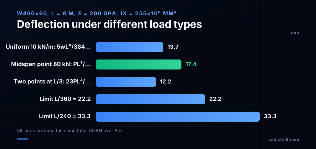
Uniform load w δ_max = 5wL⁴ / (384EI)
Point load P at midspan δ_max = PL³ / (48EI)
Example — W460×60, 8 m span, live load = 12 kN/m
W460×60: I_x = 255 × 10⁶ mm⁴
δ_L = 5 × 12 × 8000⁴ / (384 × 200000 × 255 × 10⁶) = 5 × 12 × 4.096 × 10¹⁵ / (384 × 200000 × 255 × 10⁶) = 2.458 × 10¹⁷ / (1.9584 × 10¹⁶) = 12.5 mm
Limit: L/360 = 8000/360 = 22.2 mm
12.5 mm < 22.2 mm ✓ — deflection is acceptable.
What if deflection exceeds the limit?
Options to reduce deflection: 1. Increase the moment of inertia — Use a deeper section. I_x scales roughly with d³, so a small increase in depth gives a large decrease in deflection. 2. Reduce the span — Add an intermediate support. Halving the span reduces deflection by a factor of 16 (L⁴ relationship). 3. Use composite action — A composite beam (steel + concrete slab) has an effective I that is 2–3 times the bare steel I. 4. Apply camber — Pre-curve the beam upward to offset dead load deflection. The beam arrives at the job site with a built-in upward bow.
What is floor vibration and how do you check it?
Floor vibration occurs when a person walking on a steel-framed floor causes the floor to bounce or sway perceptibly. The human body is very sensitive to vertical vibration in the 4–8 Hz range.
AISC Design Guide 11 (Floor Vibrations Due to Human Activity) provides the standard method:
Step 1 — Natural frequency
The fundamental natural frequency of the floor system must exceed a minimum value:
f_n = 0.18 × √(g / Δ_j)
Where Δ_j is the midspan deflection due to the weight supported by the beam (in mm), and g = 9810 mm/s².
Simplified: f_n ≈ 18 / √(Δ_j) Hz (with Δ_j in mm)
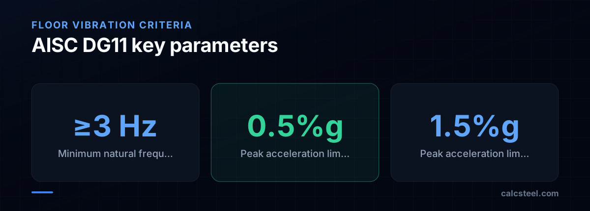
For acceptable floors: f_n ≥ 3 Hz (offices), f_n ≥ 5 Hz (sensitive areas)
Step 2 — Peak acceleration
The peak acceleration from a single walker is:
a_p/g = P₀ × exp(−0.35 × f_n) / (β × W)
Where: - P₀ = walking force constant (0.29 kN for offices) - f_n = natural frequency - β = modal damping ratio (0.02–0.05 for offices) - W = effective weight of the floor panel
Step 3 — Compare to limit
- Offices and residences: a_p/g ≤ 0.5% (ISO 2631 baseline × multiplier)
- Shopping malls: a_p/g ≤ 1.5%
- Outdoor footbridges: a_p/g ≤ 5.0%
If the peak acceleration exceeds the limit, the floor will feel bouncy to occupants even though it is structurally safe.
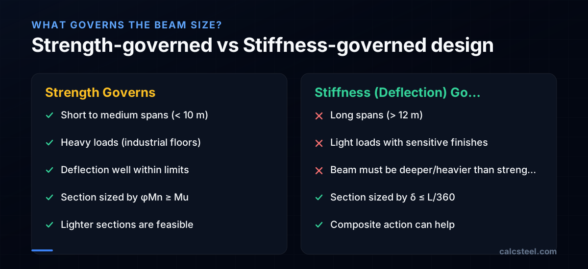
When does deflection govern the design instead of strength?
A beam is "deflection-governed" when the required moment of inertia for deflection is larger than what strength alone demands. This happens when:
Long spans (L > 10–12 m) Deflection grows as L⁴ but strength demand grows as L². So at some span, deflection catches up and overtakes strength.
Light loads with sensitive finishes A beam supporting light partitions on a 12 m span may need a W530 for deflection even though a W410 is sufficient for strength.
Cantilevers Cantilever deflection is 8× greater than a simply supported beam of the same span and load (wL⁴/8EI vs 5wL⁴/384EI). Deflection almost always governs cantilever design.
Composite beams during construction Before the concrete slab cures, the steel beam alone carries the wet concrete weight. The bare steel deflection under construction loads often governs, even though the composite section has plenty of strength and stiffness after curing.
How to tell which governs
Compare two section sizes: 1. The lightest section that satisfies φM_n ≥ M_u (strength) 2. The lightest section that satisfies δ ≤ L/360 (deflection)
The heavier of the two is the required section. If they are the same, strength and deflection are approximately balanced (the ideal situation).
How do you use camber to offset dead load deflection?
Camber is a deliberate upward curvature built into a beam during fabrication. Under dead load, the beam deflects downward and the camber flattens out, resulting in a level beam.
How much camber to specify
Camber is typically set equal to 80% of the dead load deflection:
Camber = 0.80 × δ_DL
Why 80% and not 100%? Because: - Connection slip and settlement absorb some deflection - A slight residual camber (upward bow) is less noticeable than a sag - Perfect flat is hard to achieve and not worth the precision
Example
W460×60, L = 10 m, dead load = 8 kN/m: δ_DL = 5 × 8 × 10000⁴ / (384 × 200000 × 255 × 10⁶) = 20.3 mm Camber = 0.80 × 20.3 = 16 mm → round to 15 mm
Specify on the structural drawings: "W460×60 — CAMBER 15 mm UPWARD AT MIDSPAN"
When to specify camber
- Beams longer than 8–10 m with significant dead load deflection
- Composite beams (pre-composite dead load deflection can be large)
- Beams supporting finished floors where levelness matters
- Not recommended for short beams (< 6 m) — the fabrication effort is not justified
Camber and deflection limits
Camber offsets dead load deflection only. The live load deflection limit (L/360) is checked using the live load alone, not reduced by camber. Total load deflection (L/240) can be checked against (δ_DL − camber + δ_LL).
What are common serviceability mistakes?
1. Checking deflection with factored loads Deflection limits apply to unfactored (service) loads. Using factored loads overestimates deflection by 20–60% and leads to unnecessarily heavy beams.
2. Using total load for the L/360 limit The L/360 limit applies to live load only (or the variable action only). The total load limit is L/240. Mixing them up either under-designs or over-designs the beam.
3. Ignoring floor vibration A beam with δ < L/360 can still have unacceptable vibration if it is long, lightly loaded, and lightly damped. Vibration must be checked separately using AISC DG11 or similar criteria.
4. Not considering ponding on flat roofs Flat or nearly flat roofs can accumulate rainwater in deflected areas, which increases the load, which increases the deflection — a progressive collapse mechanism. AISC Appendix 2 requires a ponding check for roofs with slope less than 25 mm/m.
5. Forgetting the construction phase Composite floor beams carry wet concrete as a non-composite beam. This construction-phase deflection can be much larger than the service-phase deflection and may require temporary shoring or camber.
6. Using inappropriate deflection limits L/360 is not universally applicable. A warehouse beam supporting nothing but metal deck can use L/240. A beam supporting MRI equipment may need L/600 or stricter. Match the limit to the actual use.
How does CalcSteel check serviceability?
CalcSteel performs comprehensive serviceability checks for every member:
Deflection check - Computes deflection for each service-level load combination - Separates live load deflection (for L/360 check) from total load deflection (for L/240 check) - Accounts for composite action when applicable - Reports the ratio δ/δ_limit for quick pass/fail assessment - Deflected shape visualization in the 3D view
Vibration check - Implements AISC DG11 walking vibration criteria - Computes natural frequency using the combined beam-slab system weight - Calculates peak acceleration for a single walker - Checks against the occupancy-specific limit (office, residential, mall)
Drift check - Story drift is computed for all lateral load combinations - Seismic drift uses amplified displacements (Cd × δxe / Ie) - Wind drift is checked against the user-defined limit (H/400 default)
Camber recommendation Based on the dead load deflection, the engine suggests an appropriate camber value for each beam. This value is included in the bill of materials and connection detail export.
Try CalcSteel for free
Model, analyze and design steel structures in your browser. No install, no signup.
Open the 3D editor