How to Size a Purlin for a Metal Roof

Choosing a purlin size looks like picking a number from a catalog, but it is really an 80-year-old engineering argument about how a thin, folded steel section behaves under a roof. This deep-dive traces where purlin design rules came from, how the math actually works, and how browser software now runs those checks in seconds.
Key takeaways
- Modern purlin sizing rests on cold-formed steel theory pioneered by George Winter at Cornell, codified in the first AISI specification in 1946.
- A purlin must pass several distinct checks - bending, the wind-uplift case, distortional and lateral-torsional buckling, shear, and deflection - not a single 'strength' number.
- Roof sheeting partially restrains the purlin; standards capture this with R-factors (AISI S908) or rotational-restraint procedures (Eurocode 3, EN 1993-1-3 clause 7.3).
- Software like CalcSteel automates the iterative effective-width and buckling math, but the engineer still owns the load case and serviceability limits.
What a purlin actually does (and why size is not one number)
A purlin is the horizontal member that spans between roof trusses or rafters and carries the metal sheeting. In light steel construction it is almost always a cold-formed C or Z section - a thin strip of high-strength steel folded into shape rather than rolled hot. That thinness is the whole story: it makes purlins light and cheap, but it also makes them prone to failure modes that a chunky hot-rolled beam never sees.
Because of this, "the right size" is never a single capacity figure. A purlin has to satisfy a family of independent limit states at once: bending strength under gravity load, a separate and often governing wind-uplift case, web shear near the supports, several buckling modes, and a serviceability deflection limit so the roof does not visibly sag or pond water. Pick a section that passes bending but fails uplift buckling and you have an unsafe roof that looks fine on paper.
Where the rules came from: Winter, Cornell, and 1946
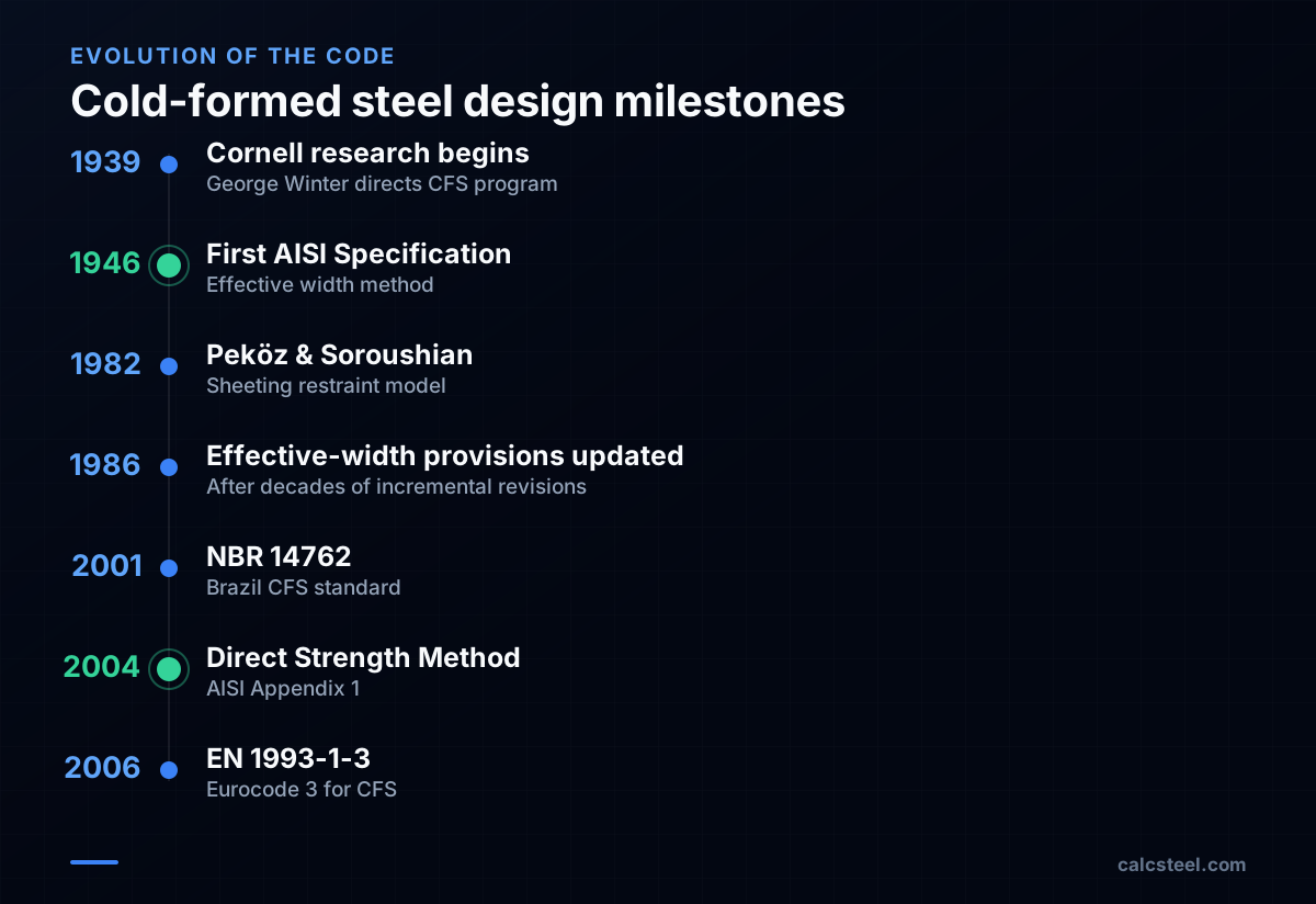
Before the 1940s there was no agreed way to design these folded sections. The breakthrough came from Professor George Winter at Cornell University, who from 1939 directed an AISI-sponsored research program on beams, studs, roof decks and connections. His team developed the effective width method - the idea that a thin compressed plate does not lose all its strength when it buckles locally; instead, only the central, already-buckled strip 'drops out' and an effective width near the stiffened edges keeps carrying load.
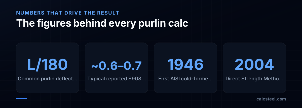
The American Iron and Steel Institute published the first cold-formed steel specification in 1946, built largely on Winter's work, and he is widely regarded as the 'grandfather of cold-formed steel design.' The effective-width philosophy he introduced anchored the AISI specification through a long series of revisions (1956, 1960, 1962, 1968, 1980 and 1986) - roughly four decades in which folded-steel roofs were designed on the framework of one professor's equations before they were substantially reworked.
The checks the software actually runs
When a tool 'sizes a purlin', it is sequencing a defined set of verifications. The historic Effective Width Method computes a reduced (effective) cross-section under each stress state, then iterates because the effective area depends on the stress, which depends on the area. The newer Direct Strength Method - adopted by AISI in 2004 as Appendix 1, developed largely by Benjamin Schafer (Johns Hopkins) building on Gregory Hancock's distortional-buckling work at the University of Sydney - skips the iteration: it runs an elastic buckling analysis of the whole cross-section to find local, distortional and global buckling loads, then maps those to member strength with calibrated curves.
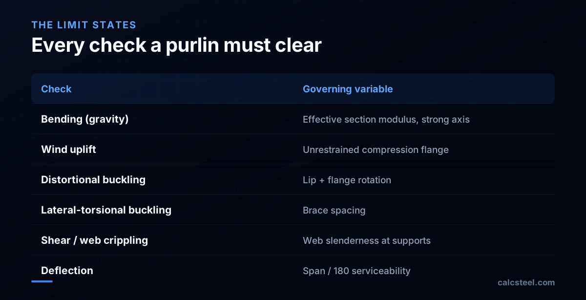
- Bending (gravity): moment capacity of the effective or full section about the strong axis.
- Wind uplift: compression flips to the unrestrained flange - frequently the governing case.
- Distortional buckling: the lip-and-flange rotate as a unit; ignored in older codes, now explicit.
- Lateral-torsional buckling: the section twists and displaces sideways between braces.
- Shear and web crippling near supports, and a deflection check, commonly L/180 for purlins.
The sheeting changes everything: R-factors and restraint
The single biggest subtlety in purlin design is that the roof itself helps. Once the metal sheeting is fixed down, it braces the purlin's top flange against lateral movement and provides rotational restraint - so the bare-section buckling capacity is too conservative. Standards handle this in two families.
North American practice uses the R-factor (reduced capacity) method: multiply the nominal flexural strength by an empirical reduction factor determined by physical 'base tests' codified in AISI S908. Reported factors for standing-seam systems often fall around 0.6 to 0.7 in practice, with the standard's tabulated defaults spanning a wider range depending on the system and configuration. Eurocode practice (EN 1993-1-3, clause 7.3) instead models the sheeting as an explicit rotational spring, an approach traced back to Peköz and Soroushian in 1982. Brazil's NBR 14762 follows the same R-factor philosophy; serviceability deflection for purlins is commonly limited to about L/180. Get the restraint assumption wrong - especially for standing-seam roofs that slide on clips - and the purlin can be badly under-designed for uplift.
Span, spacing, and the real-world trade-off
In practice the engineer juggles three coupled variables: purlin depth/gauge, spacing across the roof, and span between supports. Closer spacing lets you use a lighter section but adds more pieces and connections; a deeper section spans farther but raises material cost and eaves height. Continuous (lapped) Z-purlins over multiple supports are stronger than simple-span C-purlins precisely because the overlap doubles the section at the high-moment region.
This is an optimization problem, not a lookup. Two roofs with identical loads can need different purlins once you change the sheeting type, the wind zone, or the deflection limit the client accepts. The reason 'just copy the last job' fails so often is that the governing check quietly moves - from gravity bending on a sheltered roof to uplift distortional buckling on an exposed one.
Sizing it without the spreadsheet pain
The honest summary: purlin sizing is a multi-check, iterative, code-specific calculation where the easy mistakes are forgetting the uplift case, mis-applying sheeting restraint, or violating deflection while passing strength. That is exactly the kind of work software was built for - the engineer sets the geometry, loads and restraint assumption; the tool runs the effective-width or direct-strength checks against the chosen code.
CalcSteel is a browser-native option for this: a React/TypeScript front end with a Python analysis backend, a library of 1,140+ steel profiles, and code checks for NBR 8800, AISC 360, Eurocode 3 and IS 800 (among others). It offers a free plan, with paid Pro tiers reported around US$9 to US$24 per month depending on billing. It will not invent your wind load or pick your deflection limit for you - those remain engineering decisions - but it removes the iteration drudgery and the transcription errors. If you want to model a roof and watch the checks resolve in real time, try the editor.
Sources
- 1.Cold-formed steel - Wikipedia (history, Winter, 1946, DSM)
- 2.AISI Specifications & Manuals 1946-present - Wei-Wen Yu CFS Library, Missouri S&T
- 3.AISI S908 - Flexural Strength Reduction Factor of Purlins (Standing Seam)
- 4.AISI D111 Design Guide for Cold-Formed Steel Purlin Roof Framing Systems
- 5.Guide to Cold-Formed Steel Purlin Design - SkyCiv
- 6.EN 1993-1-3:2006 Eurocode 3 - Cold-formed members and sheeting
- 7.Image: Elliott Brown from Birmingham, United Kingdom — CC BY-SA 2.0 (Wikimedia Commons)
Try CalcSteel for free
Model, analyze and design steel structures in your browser. No install, no signup.
Open the 3D editor