What Steel Profile for a 10 m Beam?
"What steel profile should I use for a 10-meter span beam?" is one of the most-asked questions in structural design — and the honest answer is that it almost never comes down to strength. At a 10 m span, a steel beam is usually a stiffness problem. This deep-dive unpacks the engineering concept behind that, where it came from, and exactly how software computes and verifies it.
Key takeaways
- For a ~10 m beam, deflection (serviceability) typically governs the section size, not bending strength.
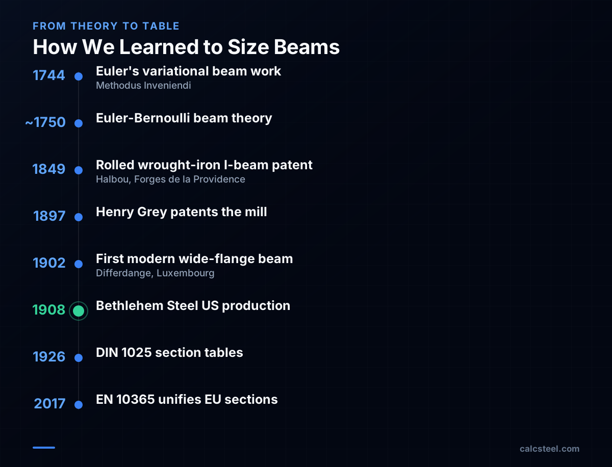
- Section tables (IPE, HEA, UB, W) trace back to Henry Grey's 1897 mill and Bethlehem Steel's 1908 production — and to Euler-Bernoulli beam theory from around 1750.
- A correct answer requires loads, spacing, bracing and the target code (NBR 8800, AISC 360, Eurocode 3, IS 800) — a single profile name is never universal.
- Modern browser tools like CalcSteel run all the checks — bending, lateral-torsional buckling, shear and deflection — against a catalog of 1,140+ profiles in seconds.
Why there is no single "right" profile
A beam is sized by what it has to carry and how it is held, not by its span alone. A 10 m beam under a light steel roof is a very different member from a 10 m floor beam in an office or a crane runway girder. The same span can land anywhere from a modest section to a deep, heavy one depending on the load, the tributary width (how many beams share the floor), the bracing of the compression flange, and the design code in force.
As a rough, load-dependent reference, industry span tables put a typical office floor beam at 10 m near a UB 457x191x67 (a roughly 457 mm deep universal beam) — but that figure assumes specific live and dead loads and spacing. Change the inputs and the answer moves. Treat any single profile name you read online as a starting hypothesis to verify, never a result.
Strength vs. stiffness: the check that actually wins
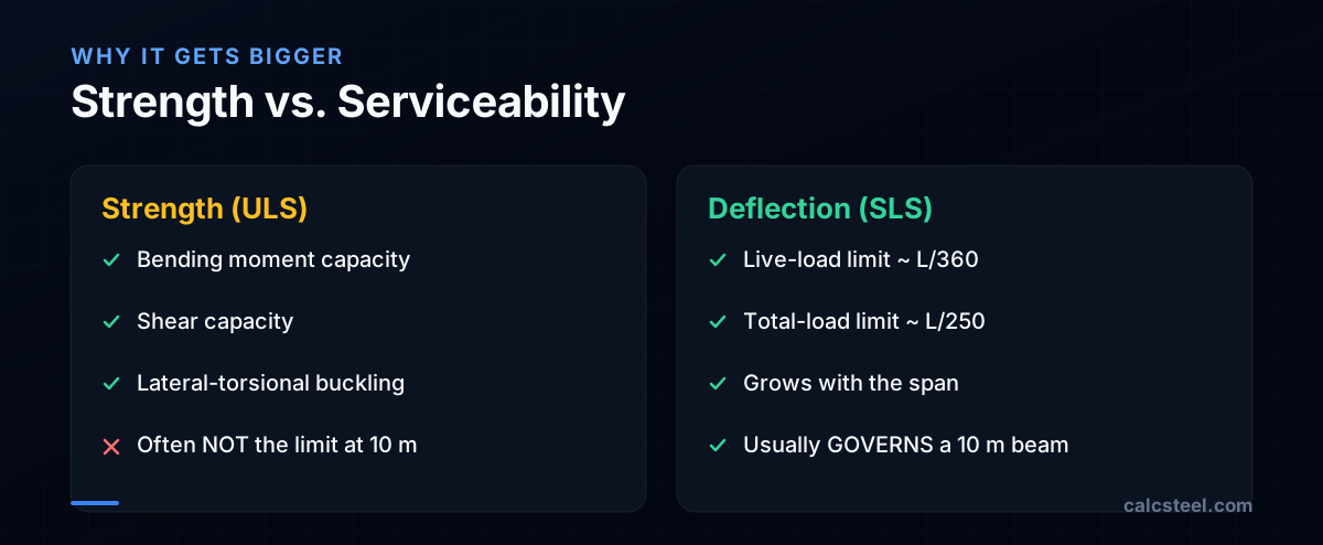
Structural design separates two questions. The ultimate limit state (ULS) asks: will it break? That covers bending capacity, shear, and stability. The serviceability limit state (SLS) asks: will it work and look right in use? That is mostly deflection and vibration.
Here is the key insight for long spans. Bending strength scales with the section modulus, but deflection scales with the moment of inertia and with the span to a high power. As the span grows, the absolute sag grows faster than the moment demand, so the beam needs to be stiffer than strength alone requires. By the time you reach roughly 10 m, the deflection check frequently decides the section — a member can be comfortably safe in bending yet still need to be deeper to keep the floor from sagging, cracking finishes, or feeling bouncy.
What the deflection limits actually mean
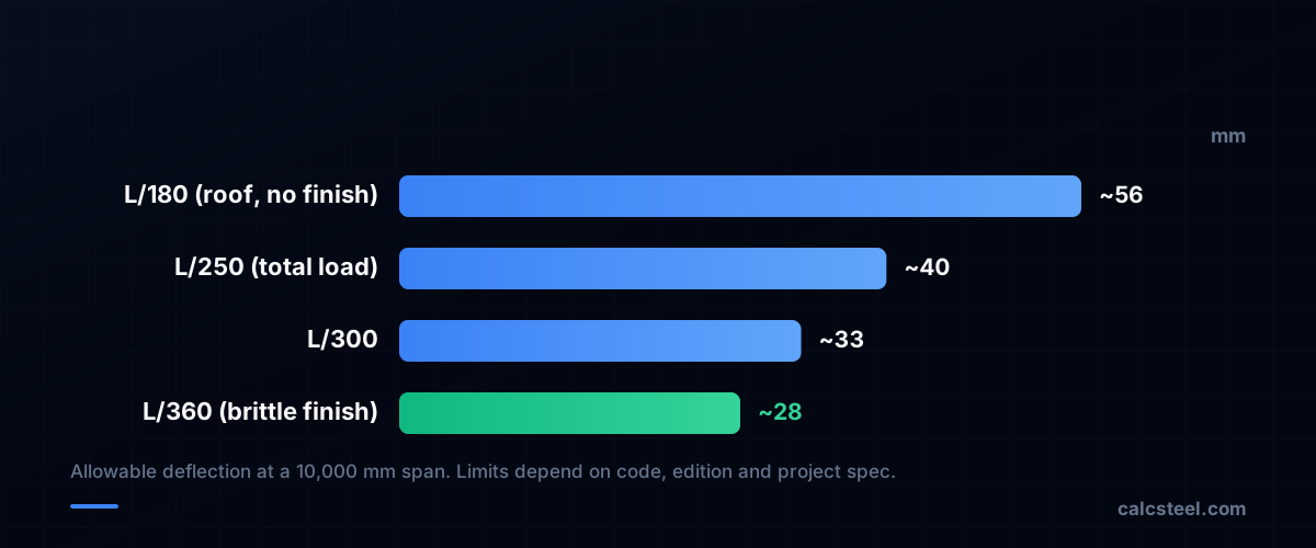
Deflection limits are written as a fraction of the span, L. A limit of L/360 means the beam may sag no more than the span divided by 360. For a 10,000 mm span that is about 28 mm under live load. The common total-load limit of L/250 permits about 40 mm. Stricter values like L/360 protect brittle finishes — plaster ceilings, drywall partitions, tile — while looser values may be acceptable for a bare roof.
These limits are a serviceability criterion, not a safety one. A beam at L/180 is not about to collapse; it may simply crack a ceiling, pond water on a flat roof, or read as visible sag to occupants. The exact limit you must meet depends on the code, its edition, and the project specification — which is why good software lets you set the target rather than hard-coding one.
Where the section tables came from
Every profile you select rests on two histories. The math came first: Leonhard Euler's 1744 variational work (the Methodus Inveniendi, with its appendix De Curvis Elasticis) and the Euler-Bernoulli beam theory that coalesced around 1750 gave engineers the relationship between load, stiffness and curvature — the foundation of the section modulus S = I / c and the deflection formulas still used today. The theory sat largely academic until the late-19th-century era of large-scale iron and steel framing made it indispensable.
The shapes came next. The single-piece rolled wrought-iron I-beam was patented by Alphonse Halbou of Forges de la Providence in 1849; Henry Grey patented his wide-flange rolling mill around 1897, and the first modern wide-flange beam was rolled at Differdange, Luxembourg in 1902. Charles Schwab bought the US rights to the Grey mill in 1905, and Bethlehem Steel began commercial US production in January 1908 — it remained the sole American producer of wide-flange shapes until U.S. Steel followed with its Carnegie beams in 1927. Those rolled families were later standardized into tables: Germany's DIN 1025 (1926), and in Europe today the unified EN 10365 (2017), which defines IPE, HE and other section dimensions and masses.
How software computes and verifies the answer
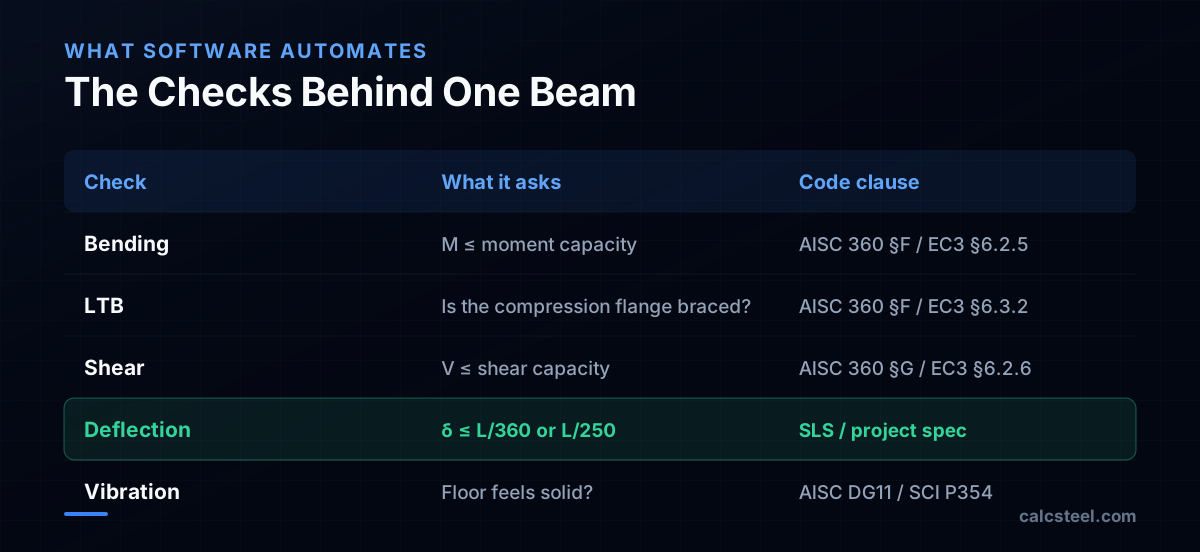
Picking a profile by hand means running several checks in sequence and iterating. Software automates exactly that loop. It builds the beam from a chosen section's tabulated properties, applies the load combinations, then verifies each limit state and reports the governing one.
The non-obvious check is lateral-torsional buckling (LTB): a slender beam can twist and buckle sideways before it reaches its full bending capacity, so the unbraced length of the compression flange matters as much as the section itself. The codes handle this differently — AISC 360 uses a three-region formulation keyed to the unbraced length, while Eurocode 3 (clause 6.3.2) applies imperfection-based reduction factors. The practical takeaway: the same beam can pass in one code and need bracing in another.
Verdict: ask for the calculation, not the name
If you take one thing away: a 10 m beam is almost always sized by stiffness, so any answer that gives you a profile name without loads, spacing, bracing and a target code is incomplete. The disciplined workflow is to set your deflection limit, define the load combinations, and let the tool report which check governs — then read the section off that.
This is exactly what CalcSteel does in the browser. It is a free-to-start, browser-native app with a React/TypeScript front-end and a Python finite-element backend, carrying a catalog of 1,140+ steel profiles and running code checks for NBR 8800, AISC 360, Eurocode 3 and IS 800 — bending, shear, lateral-torsional buckling and deflection together, with the governing limit called out. The Free plan covers real design work; paid plans are reported at roughly US$12–29/month depending on tier and billing period. Honestly, for a one-off hand check you don't need any software — but to iterate sections against several codes in seconds, open the editor, drop in a 10 m span, and let the deflection check tell you the answer.
Sources
- 1.I-beam — Wikipedia (history of rolled sections)
- 2.A Brief History of the Wide Flange Beam — Informed Infrastructure
- 3.The Bethlehem Beam Historical Marker (HMdb) — January 1908 Grey-mill production
- 4.BS EN 10365:2017 — Hot rolled steel channels, I and H sections
- 5.Euler–Bernoulli beam theory — Wikipedia (Methodus Inveniendi, 1744)
- 6.Table of properties for IPE, HEA, HEB, HEM, UB profiles — Eurocode 3 (EurocodeApplied)
- 7.Steel beam size for 3m–10m spans — Civil Sir (span reference)
- 8.Image: MassDOT — Public domain (Wikimedia Commons)
Try CalcSteel for free
Model, analyze and design steel structures in your browser. No install, no signup.
Open the 3D editor