Moment of Inertia: Why Beam Shape Beats Weight

Two steel beams can weigh the same per metre yet differ 12× in stiffness. The property behind this paradox is the moment of inertia — a single number that controls how much a beam deflects, when a column buckles, and which profile you should pick. Here is what it is, how it is calculated, and how CalcSteel uses it in every design check.
Key takeaways
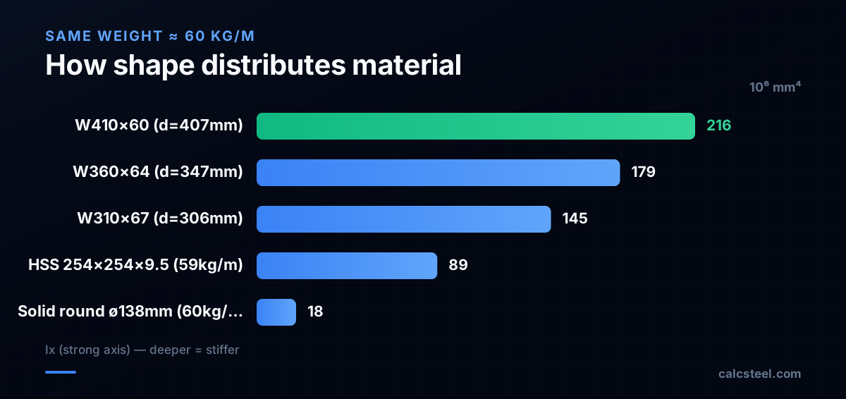
- Moment of inertia (I) measures how far material is distributed from the neutral axis. Deeper sections have exponentially higher I — a W410×60 has 12× the Ix of a solid round bar of the same weight.
- I-beams are the most efficient shape for single-axis bending because the flanges are far from the neutral axis, where material contributes most to Ix.
- Strong-axis (Ix) and weak-axis (Iy) inertia can differ 10× for I-beams. Always check which axis is loaded — bracing controls which axis governs buckling.
- CalcSteel shows Ix, Iy, Sx, Zx, rx, ry, J, and Cw for every profile. You can sort by Ix to find the lightest section that meets your deflection target.
What is the moment of inertia of a steel beam?
The moment of inertia (also called the second moment of area, symbol I) is a geometric property that measures how a cross-section's area is distributed relative to an axis. The farther the material is from the axis, the more it contributes to I — and the contribution grows with the square of the distance.
For a rectangle of width b and height h:
I = bh³ / 12
The cube in h³ is the key insight: doubling the depth increases the moment of inertia eight-fold (2³ = 8), while doubling the width only doubles it. This is why structural steel sections are deep and narrow — not short and wide.
The moment of inertia appears in two of the most important equations in structural engineering:
- Beam deflection: δ = 5wL⁴ / (384EI). Deflection is inversely proportional to I — double I, halve the deflection.
- Column buckling: Pcr = π²EI / (KL)². The critical buckling load is directly proportional to I.
In steel design tables, the moment of inertia is listed as Ix (about the strong axis, the major axis of bending) and Iy (about the weak axis). For an I-beam, Ix is typically 5–12× larger than Iy because the flanges are far from the x-axis but close to the y-axis.

How to calculate the moment of inertia of a steel section?
For standard rolled sections (W, S, HP, C, L, HSS), you never need to calculate I from scratch — the values are tabulated in the AISC Steel Construction Manual, the European section tables (IPE, HEB, HEA), or the Indian Standard section tables (ISMB, ISMC). Software like CalcSteel stores these values in its profile database.
But understanding the calculation builds intuition. For an I-beam, Ix is computed using the parallel axis theorem:
Ix = Iweb + 2 × (Iflange + Aflange × d²)
where d is the distance from the flange centroid to the section's neutral axis. The Aflange × d² term (the "transfer term") dominates — for a typical W section, 85–95% of Ix comes from the flanges, and most of that from the transfer term, not the flanges' own inertia.
For a W410×60: each flange is 178 mm × 12.8 mm at approximately ±197 mm from the centroid. The transfer term alone gives 2 × (178 × 12.8) × 197² = 2 × 2 278 × 38 809 = 177 × 10⁶ mm⁴ — that is 82% of the total Ix = 216 × 10⁶ mm⁴. The remaining 18% comes from the web and the flanges' own bh³/12.
This arithmetic explains why deeper is stiffer: increasing the depth moves the flanges farther from the neutral axis, and the I grows with d². It also explains why removing flange area (as in a coped beam) devastates the moment of inertia far more than removing web area.
Why does moment of inertia matter for beam design?
In a beam, the moment of inertia controls two things: deflection and stress distribution.
Deflection. For a simply supported beam with uniform load: δmax = 5wL⁴ / (384EI). The E (elastic modulus) is 200 000 MPa for all structural steel — you cannot change it. The only section property you can change is I. A beam with twice the I deflects half as much, everything else being equal.
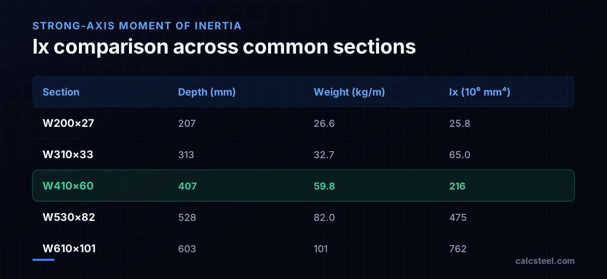
For a W410×60 (Ix = 216 × 10⁶ mm⁴) spanning 8 m with 20 kN/m service load: δ = 5 × 20 × 8 000⁴ / (384 × 200 000 × 216 × 10⁶) = 12.2 mm. The L/360 limit is 22.2 mm — comfortable.
But swap to a W310×33 (Ix = 65 × 10⁶ mm⁴, much lighter but shallower): δ = 5 × 20 × 8 000⁴ / (384 × 200 000 × 65 × 10⁶) = 40.6 mm. That is L/197 — far beyond the L/360 limit. The lighter beam cannot work, not because it lacks strength, but because it deflects too much.
Stress distribution. The extreme-fibre bending stress is σ = M × c / I, where c is the distance to the extreme fibre. The ratio I/c is the elastic section modulus Sx. A higher I (for the same depth) means a higher Sx and lower stress. This is why heavier sections of the same depth family (W410×60 vs W410×46) have higher moment capacity — they have thicker flanges, which increases I more than it increases c.
What is the difference between Ix and Iy (strong and weak axis)?
Every cross-section has two principal moments of inertia: Ix (about the horizontal x-axis, the strong or major axis) and Iy (about the vertical y-axis, the weak or minor axis).
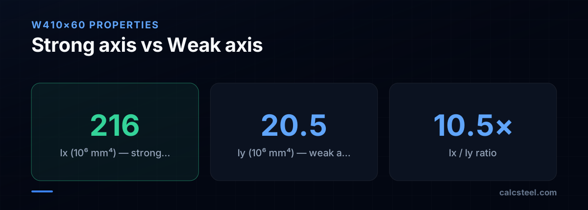
For an I-beam, the flanges are far from the x-axis but close to the y-axis. This geometric asymmetry creates a huge ratio between Ix and Iy:
- W410×60: Ix = 216 × 10⁶ mm⁴, Iy = 20.5 × 10⁶ mm⁴. Ratio: 10.5×.
- W200×27: Ix = 25.8 × 10⁶ mm⁴, Iy = 3.32 × 10⁶ mm⁴. Ratio: 7.8×.
This ratio has profound design implications:
- Beam bending: I-beams are meant to bend about the strong axis. A beam loaded about the weak axis wastes 80–90% of its material efficiency.
- Column buckling: A column buckles about its weakest axis (smallest I) unless braced. The weak-axis moment of inertia Iy and the corresponding radius of gyration ry = √(Iy/A) determine the effective length factor K and the slenderness ratio KL/ry.
- Lateral torsional buckling: The LTB capacity depends on Iy, J (torsional constant), and Cw (warping constant). Sections with low Iy relative to Ix are more susceptible to LTB.
Hollow sections (HSS, RHS, CHS) have Ix ≈ Iy, which makes them ideal for columns (equal buckling resistance in both directions) and for members under bi-axial bending or torsion.
Which steel section has the highest moment of inertia?
The answer depends on whether you want absolute Ix (the stiffest section available) or Ix per unit weight (the most efficient section).
Highest absolute Ix in the AISC manual: the W44×335 (W1100×335 in metric) with Ix ≈ 8 710 × 10⁶ mm⁴. This is a monster — 1 118 mm deep, 335 kg/m. Used for long-span transfer girders, crane runways, and bridge girders.
Highest Ix per weight: deep, lightweight W sections like the W610×82 (Ix/weight = 762/82 = 9.3 × 10⁶ mm⁴ per kg/m) outperform shallow, heavy sections like the W310×67 (145/67 = 2.2). The rule of thumb: go deeper before going heavier. A deeper section puts more material far from the neutral axis, maximising the transfer term in the parallel-axis theorem.
In European sections, the IPE family (narrow flange) gives excellent Ix/weight for beams, while the HEB family (wide flange) gives better Iy/weight for columns. CalcSteel lets you sort profiles by Ix, weight, or the ratio Ix/weight to find the optimal section for your application.

What is the moment of inertia of an I-beam vs a hollow section?
I-beams and hollow sections represent two different strategies for distributing material:
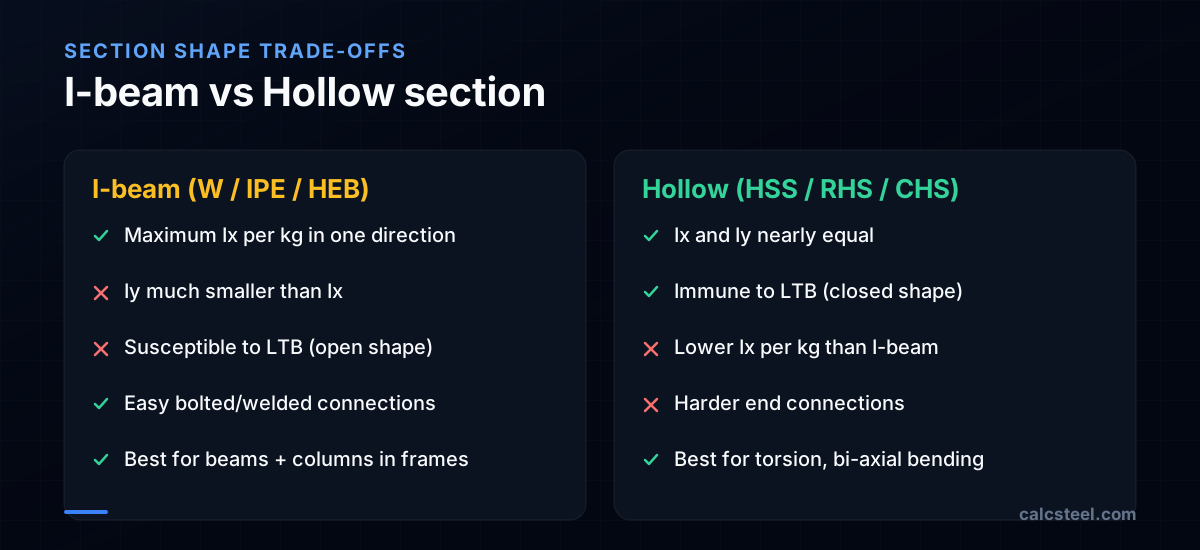
I-beams concentrate material in the flanges (far from the x-axis) to maximise Ix. The web is thin — it carries shear but contributes little to Ix. Result: very high Ix per kg, but Iy is much smaller.
Hollow sections (RHS, SHS, CHS) distribute material evenly around all four sides. Result: Ix ≈ Iy, plus high torsional stiffness (J is 100–1000× higher than I-beams). But for the same weight, Ix is lower than an I-beam's because material is "wasted" near the neutral axis (the side walls).
Numerical comparison at ~60 kg/m:
- W410×60: Ix = 216 × 10⁶ mm⁴, Iy = 20.5 × 10⁶ mm⁴. Ratio Ix/Iy = 10.5.
- HSS 254×254×9.5 (≈59 kg/m): Ix = Iy ≈ 89 × 10⁶ mm⁴. Ratio = 1.0.
The I-beam wins on Ix by 2.4×. The hollow section wins on Iy by 4.3×. This trade-off drives design decisions:
- Use I-beams for beams bending about one axis (floor beams, rafters).
- Use hollow sections for columns (equal buckling resistance), torsion members (high J), and exposed architectural elements (clean look, no open flanges).
How to find the moment of inertia in CalcSteel?
CalcSteel stores the full set of section properties for every profile in its database — AISC (W, S, HP, HSS, C, L), European (IPE, HEB, HEA, UPN), Indian (ISMB, ISMC, ISLB), and Brazilian (NBR 6355 cold-formed). Here is how to access them:
In the profile browser: Click the profile name in the Properties panel to open the section database. You can filter by family (W, IPE, HSS, etc.) and sort by any property — including Ix, Iy, weight, or Zx. The table shows all properties at a glance: A, d, bf, tf, tw, Ix, Iy, Sx, Sy, Zx, Zy, rx, ry, J, and Cw.
In the design verification panel: After running the analysis, open the design check for any member. The section properties used in the verification are displayed alongside the calculations, so you can trace exactly how Ix feeds into the deflection check or how ry feeds into the buckling slenderness.
Sorting by Ix/weight: For preliminary design, sort the profile table by Ix in descending order and look for the lightest section that meets your deflection requirement. This is faster than trial-and-error and ensures you are not over-designing.
CalcSteel also supports custom profiles: if you have a built-up section (plate girder, double angle, etc.), you can enter the dimensions and CalcSteel computes Ix, Iy, and all derived properties automatically.

Moment of inertia calculation for a steel beam step by step
Let us compute Ix for a W410×60 from its dimensional properties and verify it against the tabulated value.
Dimensions: d = 407 mm (total depth), bf = 178 mm (flange width), tf = 12.8 mm (flange thickness), tw = 7.7 mm (web thickness), h = d − 2tf = 407 − 25.6 = 381.4 mm (web clear height).
Step 1 — Flange inertia about its own centroid. Each flange is a rectangle bf × tf: Iflange,own = bf × tf³ / 12 = 178 × 12.8³ / 12 = 31 127 mm⁴ ≈ 0.031 × 10⁶ mm⁴. Tiny — this is negligible.
Step 2 — Flange transfer term. Distance from the section centroid to the flange centroid: df = (d − tf)/2 = (407 − 12.8)/2 = 197.1 mm. Aflange = bf × tf = 178 × 12.8 = 2 278 mm². Transfer term: A × d² = 2 278 × 197.1² = 88.5 × 10⁶ mm⁴. For two flanges: 177 × 10⁶ mm⁴.
Step 3 — Web inertia. Iweb = tw × h³ / 12 = 7.7 × 381.4³ / 12 = 35.6 × 10⁶ mm⁴.
Step 4 — Total. Ix = 2 × (Iflange,own + Aflange × df²) + Iweb = 2 × (0.031 + 88.5) + 35.6 = 177.1 + 35.6 = 212.7 × 10⁶ mm⁴.
The tabulated value is 216 × 10⁶ mm⁴. The small difference (~1.5%) comes from the fillets (root radii) at the web-flange junction, which add area far from the centroid. The manual value accounts for the fillets; our simplified rectangle model does not.
The takeaway: 82% of Ix comes from the flange transfer terms. The web contributes only 17%, and the flanges' own bh³/12 is negligible. This is why adding even 1–2 mm of flange thickness increases Ix dramatically — and why cutting or coping a flange is so detrimental to stiffness.

Sources
- 1.AISC Steel Construction Manual, 16th Edition — Section Properties Tables
- 2.AISC 360-22 Specification for Structural Steel Buildings
- 3.Engineering Fundamentals: Second Moment of Area (MIT OpenCourseWare)
- 4.Eurocode 3: EN 10365 — Hot rolled products (section tables)
- 5.IS 808: Dimensions for hot rolled steel beam, column, channel sections
- 6.SkyCiv: Moment of Inertia Calculator — Free Online Tool
- 7.Engineering ToolBox: Area Moment of Inertia — Formulas and Calculator
- 8.Hibbeler, Mechanics of Materials, 10th Ed. — Chapter 6: Bending
Try CalcSteel for free
Model, analyze and design steel structures in your browser. No install, no signup.
Open the 3D editor