Lateral Torsional Buckling in Steel Beams
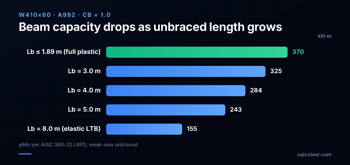
A steel beam can fail long before its cross-section reaches yield stress — not by bending too much, but by twisting sideways. This failure mode is lateral torsional buckling (LTB), and the single variable that controls it is the unbraced length Lb. Shorten Lb with one extra brace and the same W410×60 jumps from 155 kN·m to 370 kN·m — a 2.4× swing. Here is how LTB works, how the code checks it, and how to prevent it.
Key takeaways
- Lateral torsional buckling is a stability failure: the compression flange buckles sideways and the beam twists, even though the cross-section has not yielded.
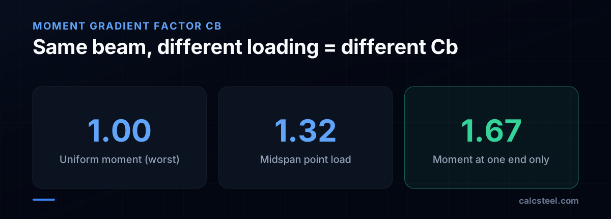
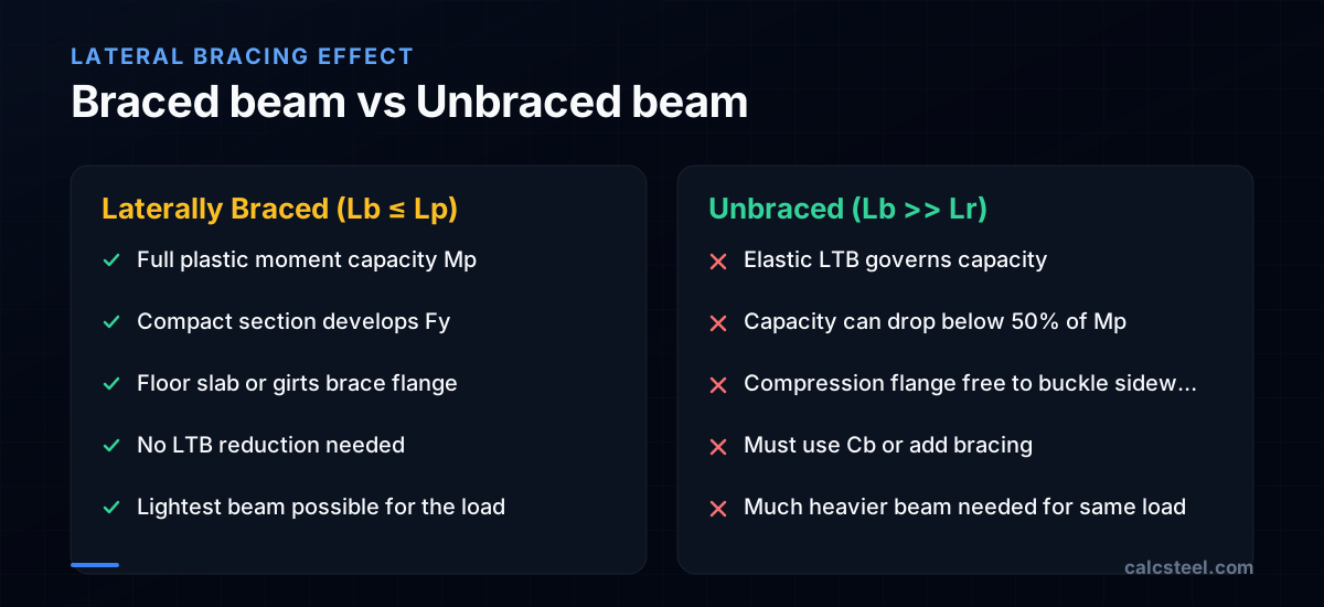
- AISC 360 divides flexural capacity into three zones based on unbraced length Lb: plastic (Lb ≤ Lp), inelastic LTB (Lp < Lb ≤ Lr), and elastic LTB (Lb > Lr).
- The moment gradient factor Cb can recover 30–67% of the capacity lost to LTB. Always compute Cb — using Cb = 1.0 is safe but wasteful.
- In CalcSteel you can set the unbraced length per member and the Cb factor is computed automatically from the actual moment diagram.
What is lateral torsional buckling in steel beams?
When a steel beam bends, the top flange goes into compression and the bottom flange into tension. If nothing restrains that top flange laterally, it can buckle sideways — just like a column buckling under axial load. But because the flange is attached to the web, the sideways movement also twists the cross-section. This coupled phenomenon — lateral displacement plus torsional rotation — is lateral torsional buckling (LTB).
LTB was first analysed mathematically by August Timoshenko in 1905, building on Euler's 1744 column-buckling solution. Timoshenko showed that the critical moment for a doubly symmetric I-beam under uniform moment is:
Mcr = (π/Lb) × √(EIyGJ + (π²E²IyCw)/Lb²)
where E = elastic modulus, Iy = weak-axis moment of inertia, G = shear modulus, J = torsional constant, Cw = warping constant, and Lb = unbraced length of the compression flange.
The formula has two stiffness terms under the square root: GJ (St. Venant torsion — resistance to uniform twisting) and ECw (warping torsion — resistance to non-uniform twisting). A wide-flange beam gets most of its LTB resistance from the warping term, which is why flanges matter so much: a W410×60 with wide flanges resists LTB far better than a narrow W410×39.
When does lateral torsional buckling occur in beams?
LTB occurs when three conditions are met simultaneously:
- The compression flange is not laterally braced. If a concrete slab, metal deck, or secondary framing continuously restrains the top flange, LTB cannot initiate. This is why composite beams (steel beam + concrete slab) almost never fail by LTB — the slab acts as a continuous lateral brace.
- The beam has an open cross-section with low torsional stiffness. I-beams and channels are susceptible because their open shape has a small torsional constant J. Hollow sections (HSS/RHS/CHS) have J values 100–1000× larger and are practically immune to LTB.
- The unbraced length Lb is long enough. Short beams fail by yielding (cross-section reaches Fy) regardless of lateral bracing. It is only when Lb exceeds the plastic-bracing limit Lp that LTB starts to reduce capacity.
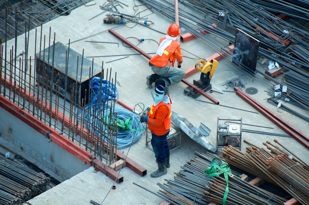
In practice, the most common LTB scenario is a roof beam or transfer girder with no floor slab and lateral bracing only at the columns (every 6–12 m). Another frequent case is the construction phase: the beam is erected but the deck/slab is not yet placed, leaving the compression flange fully unbraced over the full span.
Beams loaded in the strong axis (bending about the major axis) are susceptible. Beams loaded about the weak axis, or beams bent about any axis of a doubly symmetric closed section, do not experience LTB.
What is the Cb moment gradient factor?
The elastic critical moment formula assumes uniform moment along the unbraced length — the worst case, because every fibre of the compression flange is at maximum stress simultaneously. In reality, moment varies along the beam: a concentrated load at midspan produces a triangular moment diagram, and a cantilever has moment only at one end.
The Cb factor (moment modification factor, or moment gradient coefficient) accounts for this non-uniform moment. AISC 360-22 Equation F1-1 defines it as:
Cb = 12.5 Mmax / (2.5 Mmax + 3 MA + 4 MB + 3 MC)
where Mmax is the absolute maximum moment in the unbraced segment, and MA, MB, MC are the moments at the quarter-point, midpoint, and three-quarter-point respectively.
Key Cb values every engineer should know:
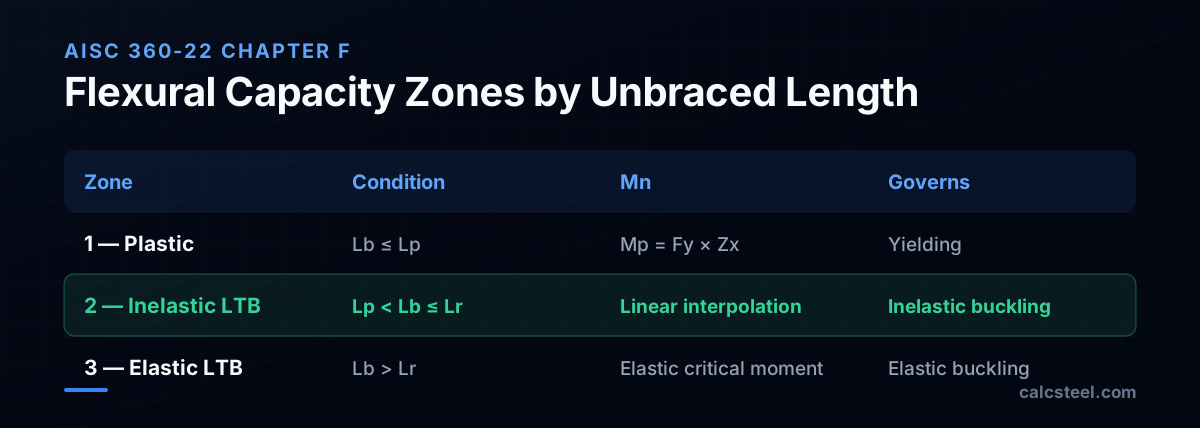
- Cb = 1.00 — Uniform moment (equal and opposite end moments). This is the baseline and the most conservative.
- Cb = 1.14 — Uniformly distributed load, simply supported.
- Cb = 1.32 — Concentrated load at midspan, simply supported.
- Cb = 1.67 — Moment at one end only (single curvature, M at one end, 0 at other).
- Cb = 2.27 — Cantilever with tip load (but AISC caps the benefit at Cb × Mn ≤ Mp).
The effect is dramatic: switching from Cb = 1.0 to Cb = 1.67 increases the available moment by 67% — for free, just by recognizing the actual loading pattern. Always compute Cb. Using Cb = 1.0 is safe but can force you to upsize the beam when the real loading pattern would have let a lighter section work.
What are the unbraced length limits Lp and Lr?
AISC 360 Chapter F defines two critical unbraced lengths that divide the flexural capacity curve into three zones:
Lp is the limiting laterally unbraced length for the limit state of yielding. For doubly symmetric I-beams:
Lp = 1.76 ry √(E / Fy)
If Lb ≤ Lp, the beam reaches its full plastic moment Mp = Fy × Zx — LTB does not govern. The 1.76 coefficient comes from calibration against test data: it ensures the compression flange can develop its full yield stress before lateral instability begins.
Lr is the limiting laterally unbraced length for the limit state of inelastic lateral-torsional buckling. The formula is more complex (AISC Eq. F2-6), involving rts, J, Sx, ho, and the 0.7Fy residual-stress assumption. For a W410×60 in A992 steel, Lr ≈ 5.3 m.
Between Lp and Lr, the capacity drops linearly from Mp to 0.7FySx. Beyond Lr, the beam enters elastic LTB territory, where capacity drops much faster — following the Timoshenko critical moment curve.
For a W410×60 (ry = 44.7 mm, Fy = 345 MPa):
- Lp = 1.76 × 44.7 × √(200 000/345) = 1.76 × 44.7 × 24.08 = 1 894 mm ≈ 1.89 m
- Lr ≈ 5.3 m
This means: if your W410×60 has lateral bracing every 1.89 m or less, you get full plastic capacity. But if the compression flange is unbraced for 5.3 m or more, elastic LTB governs and capacity can drop below half of Mp.
How to prevent lateral torsional buckling in steel beams?
LTB prevention comes down to one principle: keep the compression flange from moving sideways. The most effective strategies, in order of preference:
- Provide continuous lateral restraint. A concrete slab or metal deck attached to the compression flange via shear studs or puddle welds provides continuous bracing. Lb = 0, so Mn = Mp. This is the gold standard and why composite beams are so efficient.
- Add discrete lateral braces. Secondary beams, girts, or kickers attached to the compression flange at intervals ≤ Lp ensure full plastic capacity. Even one brace at midspan cuts Lb in half and can recover 30%+ of lost capacity. The brace must resist 2% of the compression-flange force per AISC Appendix 6.
- Use a section with high torsional stiffness. Hollow sections (HSS/RHS/CHS) have J values 100–1000× higher than open I-beams and are effectively immune to LTB. If the geometry prevents bracing (e.g., a long-span roof with no purlins), consider a rectangular tube instead of a wide-flange.
- Reduce the unbraced length. Any intermediate support — even a properly designed stiffener with a lateral tie — creates a new brace point and divides the span into shorter unbraced segments.
- Use the Cb factor. This does not prevent LTB, but it recovers capacity by recognising that the actual moment diagram is more favourable than uniform moment. Many engineers default to Cb = 1.0 and leave 20–40% of capacity on the table.
The biggest mistake in practice is forgetting about the construction condition. During erection, the beam has no slab or deck — its unbraced length equals the full span between columns. If the beam was sized assuming composite action (Lb ≈ 0), it may be grossly overstressed during construction. Always check the erection-phase LTB capacity or specify temporary lateral bracing.
How does unbraced length affect beam capacity?
Let us put numbers on the curve. Take a W410×60 (A992, Fy = 345 MPa) and compute φMn at five different unbraced lengths, all with Cb = 1.0 (uniform moment — worst case).
Section properties: Zx = 1 190 cm³, Sx = 1 060 cm³, ry = 44.7 mm, Lp = 1.89 m, Lr = 5.3 m.
- Lb ≤ 1.89 m (Zone 1 — Plastic): Mn = Mp = 345 × 1 190 × 10³ / 10⁶ = 411 kN·m → φMn = 370 kN·m.
- Lb = 3.0 m (Zone 2 — Inelastic LTB): Mn = Mp − (Mp − 0.7FySx) × (Lb − Lp)/(Lr − Lp) = 411 − 155 × (3.0−1.89)/(5.3−1.89) = 411 − 50 = 361 kN·m → φMn = 325 kN·m.
- Lb = 4.0 m (Zone 2): Mn = 411 − 155 × 2.11/3.41 = 315 kN·m → φMn = 284 kN·m.
- Lb = 5.0 m (Zone 2, near Lr): Mn = 411 − 155 × 3.11/3.41 = 270 kN·m → φMn = 243 kN·m.
- Lb = 8.0 m (Zone 3 — Elastic LTB): At this length, the elastic critical moment Mcr governs. Fcr drops roughly with 1/Lb², giving Mn ≈ 172 kN·m → φMn ≈ 155 kN·m — only 42% of the full plastic capacity.
From Lb = 1.89 m to Lb = 8 m, the beam lost 58% of its moment capacity. Adding a single brace at midspan (cutting Lb from 8 m to 4 m) would recover nearly 130 kN·m of capacity — that is the power of understanding LTB.

How to check lateral torsional buckling in CalcSteel?
CalcSteel automates the full AISC 360 Chapter F procedure — including the Cb computation from the actual moment diagram. Here is how the LTB check works in the app:
Step 1 — Set the unbraced length. Select a beam member and open the Properties panel. The Unbraced length Lb field defaults to the full member length (conservative). To model intermediate bracing, enter the actual unbraced length or add brace points in the 3D model. CalcSteel accepts different unbraced lengths for the compression flange (Lb) and for the weak axis.
Step 2 — Run the analysis. CalcSteel solves the frame, extracts the moment envelope for each load combination, and automatically computes Cb using AISC Eq. F1-1 with the quarter-point moments. You never need to look up Cb from a table — the software reads it from the actual moment diagram.
Step 3 — Read the flexural verification. Open the Design Verification panel and look at the Flexural section. CalcSteel reports:
- Lp and Lr for the selected profile
- The governing zone (yielding, inelastic LTB, or elastic LTB)
- Cb computed from the moment diagram
- Mn before and after the Cb adjustment
- φMn (LRFD) or Mn/Ω (ASD)
- The utilisation ratio Mu/φMn
You can instantly experiment: change Lb and watch the utilisation ratio jump. If adding one brace at midspan drops the ratio from 1.05 to 0.72, you know the brace pays for itself many times over.
The screenshot below shows CalcSteel's flexural design verification panel with the LTB check and Cb factor displayed.

Steel beam flexural capacity calculation step by step
Let us walk through a complete AISC 360-22 LRFD flexural check for a W410×60 beam (A992, Fy = 345 MPa) with Lb = 4.0 m and Cb = 1.0, then show the effect of applying Cb = 1.32 (midspan point load).
Step 1 — Section properties. From the AISC Manual (or CalcSteel's profile database): Zx = 1 190 cm³, Sx = 1 060 cm³, ry = 44.7 mm. Steel: E = 200 000 MPa, Fy = 345 MPa.
Step 2 — Plastic moment. Mp = Fy × Zx = 345 × 1 190 × 10³ / 10⁶ = 411 kN·m.
Step 3 — Compute Lp. Lp = 1.76 × ry × √(E/Fy) = 1.76 × 44.7 × √(200 000/345) = 1 894 mm ≈ 1.89 m.
Step 4 — Check the zone. Lb = 4.0 m, Lr ≈ 5.3 m. Since Lp (1.89) < Lb (4.0) ≤ Lr (5.3), we are in Zone 2 — Inelastic LTB.
Step 5 — Nominal moment (Cb = 1.0). Mn = Cb × [Mp − (Mp − 0.7FySx)(Lb − Lp)/(Lr − Lp)] ≤ Mp
= 1.0 × [411 − (411 − 256) × (4.0 − 1.89)/(5.3 − 1.89)]
= 411 − 155 × 2.11/3.41 = 411 − 96 = 315 kN·m.
φMn = 0.9 × 315 = 284 kN·m. That is only 69% of the full plastic capacity Mp.
Step 6 — With Cb = 1.32 (midspan point load). Mn = 1.32 × 315 = 416 kN·m. But Mn ≤ Mp = 411, so Mn = 411 kN·m (capped at Mp).
φMn = 0.9 × 411 = 370 kN·m — the Cb factor recovered the full plastic capacity!
The lesson: for a beam with a midspan concentrated load and Lb = 4.0 m, the moment gradient is favourable enough that Cb = 1.32 erases the LTB penalty entirely. Ignoring Cb (using 1.0) would have cost you 86 kN·m of capacity — potentially forcing an unnecessary beam upsizing.
In CalcSteel, this entire calculation runs automatically. The screenshot below shows the AISC flexural verification with the computed Cb factor and the capacity comparison.
Sources
- 1.AISC 360-22 Specification for Structural Steel Buildings — Chapter F: Flexure
- 2.AISC Design Guide 25: Frame Design Using Web-Tapered Members
- 3.NBR 8800:2024 — Projeto de estruturas de aço (Item 5.4: Flexão)
- 4.Timoshenko & Gere, Theory of Elastic Stability (Chapter 6: Lateral Buckling of Beams)
- 5.SkyCiv: Lateral Torsional Buckling of Beams
- 6.Steel Construction Manual, 16th Edition: Cb Values for Common Loading Cases
- 7.Eng-Tips: Lateral torsional buckling Cb factor (forum thread)
- 8.FicientDesign: Beam Lateral Torsional Buckling Step-by-Step
Try CalcSteel for free
Model, analyze and design steel structures in your browser. No install, no signup.
Open the 3D editor