Indeterminate Beam: The Criterion Behind the Code, With a Worked Check
The indeterminate beam you actually design is the continuous beam, one member running over three or more supports, and it does not behave like the single spans in a textbook. Its moments redistribute, its supports can lift, and the load case that governs is almost never the obvious one. The criterion behind the code is what decides all three: how the moments split between span and support, and which arrangement of load you are required to check. Here is that criterion worked two ways on one continuous beam, solved by the classical three-moment theorem and confirmed in the real CalcSteel FEM engine to three decimals, ending in the moment envelope you would actually size the section from.
Key takeaways
- The everyday indeterminate beam is the continuous beam over several supports. Its degree of static indeterminacy is simply the number of redundant supports: a two-span beam on three simple supports is DSI 1.
- The classical criterion for it is the three-moment theorem (Clapeyron). For two equal spans fully loaded it gives the interior support moment directly as wL2/8, no matrix required.
- Worked and verified in the real CalcSteel FEM engine to three decimals (L = 6 m per span, w = 20 kN/m). Both spans loaded: interior support moment 90 kN·m hogging, reactions 45, 150, 45 kN, span sagging 50.625 kN·m.
- Pattern loading is the criterion behind the code, and it changes the answer. Load one span only and the span sagging jumps to 68.906 kN·m, 36 percent higher than the fully loaded case, the interior moment falls to 45 kN·m, and the far support lifts with a 7.5 kN uplift.
- You size the section from the envelope, not one load case: max hogging 90 kN·m from the full load, max sagging 68.906 kN·m from the pattern. Miss the pattern and you undersize the span by about a quarter.
The indeterminate beam is the continuous beam
Ask an engineer to picture an indeterminate beam and they rarely picture a fixed-ended single span. They picture the beam that runs unbroken over a line of columns, one member, several supports: a continuous beam. It is the most common indeterminate member in real steel, the floor girder over three columns, the purlin line over a row of frames, the crane runway spanning bay after bay, and it is where indeterminacy stops being a definition and starts changing what you build.
A continuous beam does three things a set of simple spans never does. It redistributes moment, shedding bending from midspan onto the interior supports as hogging. Its supports can lift off under the wrong load pattern. And the load case that produces the largest span moment is not the one with every span loaded. Each of those is governed by the same criterion, the one sitting behind both the solver and the design code, and in this article we work it on one continuous beam, two ways, and confirm every number in the shipping CalcSteel FEM engine to three decimals. If you want the general definition of indeterminacy and how to count the degree for any structure, our companion piece on indeterminate structures covers that ground; here we stay on the beam.
How indeterminate is it? Count the redundant supports
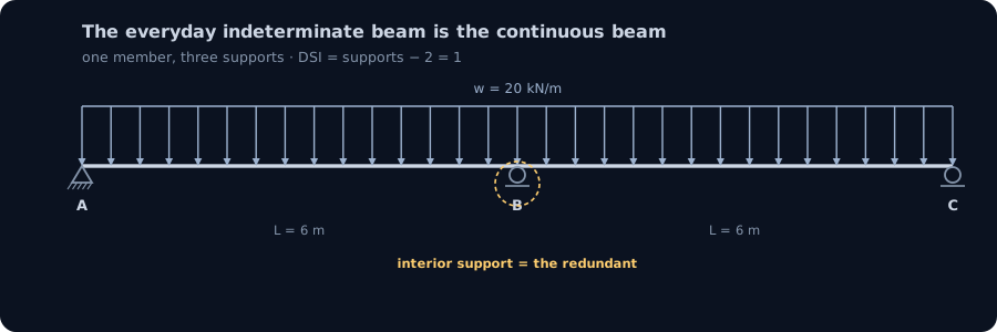
The degree of static indeterminacy of a continuous beam is refreshingly easy to count, because the redundants are the supports themselves. A single simply supported span needs exactly two vertical reactions, plus one horizontal restraint to be stable in plane, and statics supplies exactly enough equations to find them: it is determinate. Every interior support you add after that puts in one more vertical reaction than statics can solve, and each one is a redundant.
So for a continuous beam on simple supports the rule is just DSI = number of supports − 2 (counting the two vertical reactions the determinate span already needed). A beam on three supports is DSI 1, on four supports DSI 2, on five supports DSI 3, and so on. Build one end in as a fixed support instead of a pin and you add one more redundant, because a fixed end carries a moment reaction the pin does not. The two-span beam we work below sits at the bottom of that ladder, DSI 1: three supports, one redundant, one extra condition needed beyond statics. That one condition is what the three-moment theorem supplies.
The criterion, the classical way: the three-moment theorem
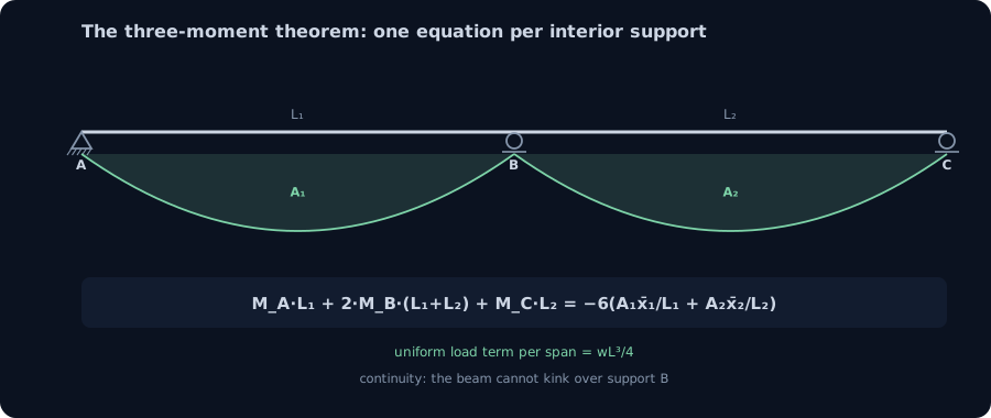
Long before stiffness matrices, engineers solved continuous beams with one elegant equation, Clapeyron's three-moment theorem, and it is still the fastest hand check there is. It works on the redundant that the criterion identified, the bending moment over each interior support, and turns compatibility (the beam is continuous, so it cannot kink at a support) into a single linear equation linking three consecutive support moments.
For two spans of length L₁ and L₂ meeting over an interior support, with the supports at the same level and constant EI, the theorem reads:
MA·L₁ + 2·MB·(L₁ + L₂) + MC·L₂ = −6·(A₁x̄₁/L₁ + A₂x̄₂/L₂)
The right-hand side is the load term: for a span carrying a uniform load w it evaluates to wL³/4. That is the entire method for a two-span beam. Both ends of our beam are simply supported, so MA = MC = 0, the equation collapses to one unknown, the interior moment MB, and every reaction follows from statics once that moment is known. No matrix, no iteration, one line of algebra per interior support. The criterion told us we owed exactly one compatibility condition; the three-moment equation is that condition, written down.
One continuous beam, two load cases
We hold the structure fixed and change only the load. The beam has two equal spans of L = 6 m on three simple supports A, B and C, and where it is loaded it carries w = 20 kN/m. We keep the same span and load as the single-span cases in the companion article on purpose, so you can see exactly what continuity does to the same beam. Two arrangements tell the whole story:
- Case A, both spans loaded. The symmetric, obvious case. It produces the largest hogging moment over the interior support.
- Case B, one span loaded. The pattern case the code forces you to check. It produces the largest sagging moment in a span, and it lifts the far support off its seat.
Both were built in the shipping CalcSteel FEM engine, each span subdivided into 48 elements, and both are checked against the three-moment theorem to three decimals. Watch which case governs which moment; the answer is why the envelope at the end exists at all.
Case A: both spans loaded, worked and checked
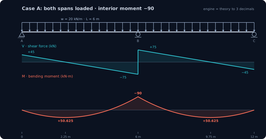
With both spans carrying w, the beam is symmetric, so MA = MC = 0 and the three-moment equation over B has a uniform load term on each side:
2·MB·(2L) = −(wL³/4 + wL³/4) ⟹ MB = −wL²/8 = −90 kN·m
The interior support takes a hogging moment of 90 kN·m, the same magnitude a simply supported span of this size would peak at, but pulled onto the support instead of sitting at midspan. Statics finishes the job. Each end reaction is 3wL/8 = 45 kN, the interior support carries 5wL/4 = 150 kN (it serves two spans), and the largest sagging moment in each span is 9wL²/128 = 50.625 kN·m, at x = 3L/8 = 2.25 m from the outer support. The moment crosses zero, the point of contraflexure, at x = 3L/4 = 4.5 m.
The CalcSteel engine returns an interior support moment of −90.000 kN·m, reactions of 45.000, 150.000 and 45.000 kN summing to exactly 240 kN = 2wL, and a span sagging peak of +50.625 kN·m at x = 2.250 m. Every number matches. Notice the structural bargain: a symmetric two-span continuous beam behaves exactly like two propped cantilevers set back to back, the interior support acting as the built-in end. That is why the 90 and the 50.625 are identical to the propped-cantilever numbers in the companion piece. Then we change the load, and the equivalence breaks.
Case B: pattern loading, worked and checked
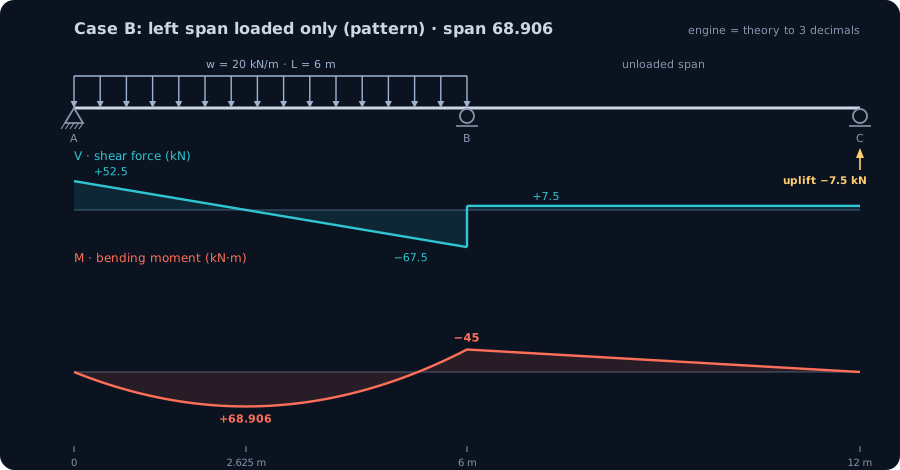
Now load only the left span and leave the right span bare. This is the arrangement the design code makes you consider, and the three-moment equation over B keeps the load term on the loaded side only:
2·MB·(2L) = −(wL³/4 + 0) ⟹ MB = −wL²/16 = −45 kN·m
The support moment has halved, from 90 to 45 kN·m, because only one span is now leaning on the support. But watch what happens to the loaded span. Its reactions become RA = 7wL/16 = 52.5 kN and the interior support gives 5wL/8 = 75 kN, so the shear crosses zero further out, at x = 2.625 m, and the sagging moment there climbs to 49wL²/512 = 68.906 kN·m. That is 36 percent higher than the fully loaded case, on the identical beam, purely because the empty right span no longer helps to hog the support down over the load.
And the far support tells the other half of the story. With nothing on span BC, the reaction at C comes out negative, RC = −wL/16 = −7.5 kN: the beam is trying to lift the end off its support. On a beam that is only resting on a seat, the end rises and the analysis you ran, which assumed a bilateral support, no longer describes the real structure.
The CalcSteel engine confirms it to the decimal: interior support moment −45.000 kN·m, reactions 52.500, 75.000 and −7.500 kN (still summing to 120 kN = wL, one span's worth), and a loaded-span sagging peak of +68.906 kN·m at x = 2.625 m. The pattern that looked like a lighter load produced the heavier span moment and an uplift the symmetric case completely hides.
You size the beam from the envelope, not one case
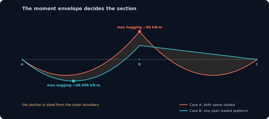
Here is why continuous beams are worked with load patterns at all. No single load case gives you both governing moments. Lay the two cases on top of each other and the design values fall out of the overlay:
- Maximum hogging over the interior support: 90 kN·m, from Case A (both spans loaded).
- Maximum sagging in a span: 68.906 kN·m, from Case B (one span loaded), not the 50.625 kN·m of the fully loaded case.
That overlay is the moment envelope, and it is the real deliverable of a continuous-beam analysis. By symmetry, loading the other span instead drives its sagging to the same 68.906 kN·m, so the full design envelope carries that peak in both spans. You size the top flange, the bottom flange and the connections from the worst value each experiences across all the patterns, not from one tidy symmetric run. An engineer who checks only the fully loaded case reads a span moment of 50.625 kN·m and sizes for it, and lands about a quarter under the true demand. The redundancy that let the beam shed moment onto its supports is the same redundancy that makes the load pattern matter, and the envelope is where both effects are finally accounted for together.
The criterion behind the code
"The criterion behind the code" has two honest readings for a continuous beam, and load pattern sits behind both.
Behind the load code. Because an indeterminate beam responds to where the live load sits, not just how much of it there is, loading standards require you to consider adverse arrangements. Eurocode EN 1991-1-1 and its base EN 1990 make you place the variable action on the spans that produce the worst effect and leave it off the others, exactly our Case B. North American practice calls the same idea pattern or skip loading for continuous members, and ABNT NBR 8800 carries the corresponding load-combination requirement. The permanent load is everywhere; the live load is placed to hurt. The code is written this way precisely because indeterminacy makes the pattern matter.
Behind the design code. Steel design standards, AISC 360, NBR 8800 and Eurocode EN 1993-1-1, are then built on top of that redistribution. They permit a limited, controlled redistribution of the negative moment over interior supports of continuous compact-section beams, lowering the support moment and raising the span moment to match, provided the section is ductile enough to rotate and deliver it. The redundancy the three-moment theorem counted is the same redundancy the design code lets you bank, up to the ductility the steel can actually supply. Count it, pattern it, then spend it: that is the criterion closing the loop.
Try it: build the continuous beam and load it both ways
The calculator below runs the same direct stiffness method as the worked cases, live in your browser. Build the two-span beam, load both spans and read the interior moment fall to 90 kN·m with 45, 150, 45 kN reactions; then clear the right span and watch the span moment climb to 68.9 kN·m and the far reaction go negative. Run the checks yourself: the reactions still sum to the load on the beam, and the interior support moment stays between wL²/16 (one span) and wL²/8 (both spans) every time.
It is free, no login for the analysis, and it does not stop at two spans. Add supports until you have a five-span continuous girder no hand method would enjoy, and it still solves, still balances, and still traces the envelope in the same instant.
Max moment
45 kN·m
Max shear
30 kN
Max deflection
10.55 mm
= L/569
Bending stress σ
84.4 MPa
σ = M/Sx
Utilization
44.0%
NBR 8800 · δ ≤ L/250
Geometry & supports
Section
Ix 7999 cm⁴ · Sx 533 cm³ · 42.2 kg/m
Point loads (↓ positive)
None — add as many as you need.
Distributed loads (uniform or trapezoidal)
Model sketch
Diagrams — free PNG / SVG / CSV export, no watermark
Step-by-step — the calculation memory of YOUR beam
IPE 300 · L = 6 m · fy = 250 MPa
1. Reactions (equilibrium of the solved FEM model)
ΣFy = 0 · ΣM = 0
R_A = 30 kN · R_B = 30 kN
2. Peak shear (read from the SFD)
Vmax = |V(x)|max
Vmax = -30 kN @ x = 6 m
3. Peak moment (read from the BMD)
Mmax = |M(x)|max
Mmax = 45 kN·m @ x = 3 m
4. Peak deflection
EI = 15998 kN·m² (E = 200 GPa)
δmax = 10.55 mm @ x = 3 m = L/569
5. Elastic bending stress
σ = Mmax / Sx = 45.00 × 10³ / 533.3
σ = 84.4 MPa
6. Bending check — both codes, side by side
NBR 8800: σ ≤ fy/1.10 = 227.3 MPa · AISC 360: σ ≤ 0.90·fy = 225 MPa
NBR 37.1% PASS · AISC 37.5% PASS
7. Deflection check (serviceability — code-independent)
δ ≤ L/250 = 24 mm
10.55 mm / 24 mm = 44.0% PASS
Recomputed live from the current inputs by the direct-stiffness FEM engine — change any load and every step updates. Reproduce it by hand with the formulas in the sections below.
Lightest catalog profiles that pass (974 flexural candidates · NBR 8800)
| Profile | Std | Weight | Total steel | σ util | δ util | |
|---|---|---|---|---|---|---|
| W310x21 | AISC | 21 kg/m | 126 kg | 83% | 98% | |
| VS 300x23 | BR | 22.6 kg/m | 136 kg | 71% | 84% | |
| U 300x90x6.3 | BR | 23.1 kg/m | 139 kg | 82% | 98% | |
| U 300x100x6.3 | BR | 24.1 kg/m | 145 kg | 77% | 91% | |
| VS 250x25 | BR | 24.6 kg/m | 148 kg | 70% | 100% |
Elastic bending (σ = M/Sx vs fy/γa1, γa1 = 1.10 — NBR 8800) + deflection screening of the full flexural catalog. Lateral-torsional buckling, shear and local buckling are NOT checked here — run the full NBR 8800 / AISC 360 verification in the 3D editor.
How to check a continuous-beam result you did not hand-solve
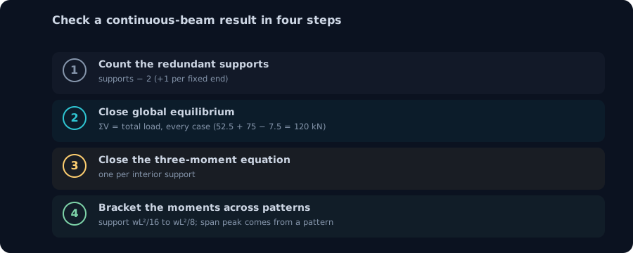
You will let the solver handle the real continuous beams. The skill that matters is auditing what it returns, and the criterion tells you exactly what to audit. Four checks, in order, catch the overwhelming majority of modelling errors on a continuous beam.
1. Count the redundants. Supports minus two (plus one for each fixed end) is the degree. A model you expected to be DSI 2 that counts out at DSI 0 has a support missing or a release you did not mean to add. It also tells you how many interior support moments the solver had to resolve.
2. Close global equilibrium. Sum the vertical reactions and they must equal the total applied load, for every load case. In Case B, 52.5 + 75 − 7.5 = 120 kN, exactly wL. If a reaction comes out negative, do not dismiss it, that is a real uplift, and on a gravity-only seat it means the model and the structure have parted ways.
3. Close the three-moment equation at each interior support. This is the compatibility check equilibrium cannot give you, one per redundant. Take the support moments the solver reports and put them back into MAL₁ + 2MB(L₁+L₂) + MCL₂ = −6(...); it should balance. For our beam it reproduces −90 and −45 kN·m for the two cases directly.
4. Bracket the moments across patterns. For equal spans under a uniform live load, the interior support hogging lives between wL²/16 and wL²/8, and the largest span sagging comes from a pattern case and exceeds the fully loaded span value. If your envelope shows the biggest span moment coming from the all-spans-loaded run, you forgot to pattern the load.
Run those four and you are holding the solver to the same physics you would have used by hand, at a fraction of the effort.
Common mistakes and FAQ
Checking only the fully loaded case. The single most common continuous-beam error. The symmetric all-spans-loaded run gives the maximum support hogging but understates the span sagging, here by 36 percent. The governing span moment lives in a pattern case.
Ignoring uplift. A negative reaction under an unloaded span is not a rounding artefact; it is the beam lifting off. On a simple seat the support does not hold it down, the real beam has fewer active supports than your model, and the moments are different again. Either detail the connection to take tension or check the case with that support removed.
Assuming the section does not matter. For a determinate beam the internal forces are independent of the section, and for a prismatic continuous beam of one uniform section they still are, which is why our C-section benchmark reproduces the theory exactly. But the instant the spans have different sections, or the supports settle, the moments redistribute with relative stiffness. Change a member on a real continuous beam and its neighbours feel it.
Is a continuous beam always lighter than simple spans? Usually, because the support hogging lets the span moment drop, but only if you also carry the negative moment and its connection, and only after the pattern case is checked. The saving is real but it is not free.
Do I still need the three-moment theorem if the solver handles it? Yes, as a check. It is the one-line hand calculation that confirms the solver resolved the redundant correctly, and it is how you catch a wrong span length or a missing support before it reaches the drawing.
Does the pattern case need a different combination? No, the same load factors apply; you just place the live load on the adverse spans. The permanent load stays on every span; only the variable load is patterned.
Key takeaways
- The indeterminate beam you design in practice is the continuous beam. Its degree of indeterminacy is the number of redundant supports: supports minus two, plus one per fixed end. Our two-span beam is DSI 1.
- The three-moment theorem is the criterion the classical way: one linear equation per interior support. For two equal fully loaded spans it gives the interior moment as wL²/8 directly.
- Every number was computed by the shipping CalcSteel FEM engine and matches the three-moment theorem to three decimals. Both spans loaded: −90 kN·m over the support, reactions 45, 150, 45 kN, span +50.625 kN·m. One span loaded: −45 kN·m, reactions 52.5, 75, −7.5 kN, span +68.906 kN·m.
- Pattern loading is the criterion behind the code. It drives the span moment 36 percent above the fully loaded value and lifts the far support. You size from the envelope, max hogging 90 kN·m and max sagging 68.906 kN·m, not from any single case.
- Audit the solver, do not trust it: count the redundants, close equilibrium for every pattern, close the three-moment equation at each interior support, and bracket the moments across patterns.
Sources
- 1.Hibbeler, Structural Analysis (continuous beams, the three-moment equation)
- 2.Kassimali, Structural Analysis (Clapeyron's theorem of three moments)
- 3.Eurocode EN 1990 and EN 1991-1-1 (arrangement of variable actions on continuous members)
- 4.AISC 360, Specification for Structural Steel Buildings (analysis and moment redistribution)
- 5.ABNT NBR 8800, Projeto de estruturas de aco e de estruturas mistas de aco e concreto
- 6.Eurocode EN 1993-1-1, Design of steel structures: General rules (global analysis, redistribution)
Try CalcSteel for free
Model, analyze and design steel structures in your browser. No install, no signup.
Open the 3D editor