How to Size a Steel Beam: AISC 360 Guide
Learn the six-step procedure to select the lightest W-shape for any beam. Covers required section modulus, limit state checks, and deflection limits per AISC 360-22.
How do you select the right size steel beam for a given load?
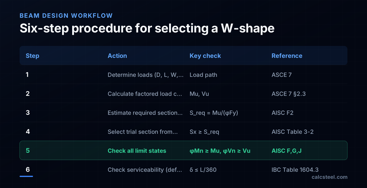
Sizing a steel beam means finding the lightest section that satisfies strength, stability, and serviceability requirements. The process follows a clear sequence:
- Determine the loads on the beam
- Calculate the maximum factored moment M_u and shear V_u
- Estimate the required section modulus S_req
- Pick a trial W-shape from the AISC tables
- Verify all limit states (flexure, shear, LTB, web crippling)
- Check deflection under service loads
This guide walks through each step with a worked example: a simply supported floor beam spanning 9 m, carrying a dead load of 8 kN/m and a live load of 12 kN/m, with lateral bracing at the compression flange provided by the concrete slab.
The goal is always the lightest section that passes every check. A deeper beam with a thinner web is usually lighter than a shallower, heavier section — so start with the deepest group and work down.
How do you calculate the required section modulus for a steel beam?
The required plastic section modulus Z_x (or elastic section modulus S_x for non-compact sections) comes from the design moment:
Step 1 — Factored moment
Using ASCE 7-22 combination 2 (1.2D + 1.6L):
- w_u = 1.2(8) + 1.6(12) = 9.6 + 19.2 = 28.8 kN/m
- M_u = w_u × L² / 8 = 28.8 × 9² / 8 = 28.8 × 81 / 8 = 291.6 kN·m
Step 2 — Required section modulus
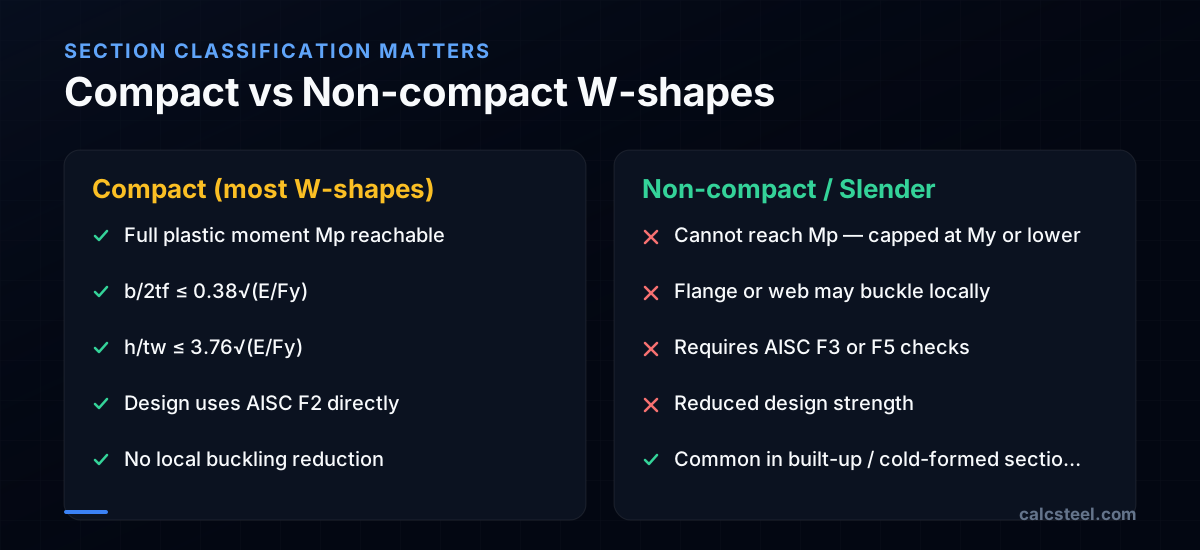
For a compact section with full lateral bracing (L_b ≤ L_p), the nominal moment equals the plastic moment:
φM_n = φ × F_y × Z_x
Solving for Z_x:
Z_req = M_u / (φ × F_y) = 291.6 × 10⁶ / (0.90 × 345) = 291.6 × 10⁶ / 310.5 = 939 × 10³ mm³ = 939 cm³
Now open AISC Table 3-2 (W-shapes sorted by Z_x) and find the lightest section with Z_x ≥ 939 cm³. The W460×60 has Z_x = 1120 cm³ — but let us check a deeper, lighter option: the W530×66 has Z_x = 1340 cm³.
> CalcSteel tip: The section selection tool does this lookup instantly — enter your moment and bracing conditions, and it returns the lightest section from the full database.
What limit states must you check when sizing a steel beam?
AISC 360-22 requires you to verify several limit states. For a typical floor beam:
Flexure (AISC Chapter F)
- Yielding (F2.1): φM_n = φ × M_p = 0.90 × F_y × Z_x. For W530×66 (Z_x = 1340 cm³): φM_n = 0.90 × 345 × 1340 × 10⁻³ = 416 kN·m > 291.6 kN·m ✓
- Lateral-torsional buckling (F2.2): Only governs if L_b > L_p. With continuous slab bracing, L_b ≈ 0, so LTB does not control.
- Flange local buckling (F3): Only for non-compact flanges. Check b_f/(2t_f) ≤ 0.38√(E/F_y) = 0.38√(200000/345) = 9.15. The W530×66 has b_f/(2t_f) = 7.6 — compact ✓
Shear (AISC Chapter G)
- V_u = w_u × L / 2 = 28.8 × 9 / 2 = 129.6 kN
- φV_n = φ × 0.6 × F_y × A_w = 1.0 × 0.6 × 345 × (d × t_w)
- For W530×66: d = 525 mm, t_w = 8.9 mm → A_w = 4673 mm² → φV_n = 0.6 × 345 × 4673 × 10⁻³ = 967 kN >> 129.6 kN ✓
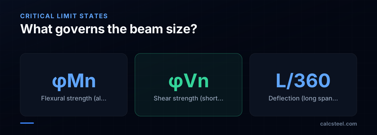
Shear almost never governs for standard W-shapes under uniform loads — it only becomes critical for short, heavily loaded beams or beams with large web openings.
How do you check deflection limits for a steel beam?
Deflection is a serviceability check using unfactored (service) loads. The common limits per IBC Table 1604.3 are:
- Live load only: L/360 (floors), L/240 (roofs)
- Total load (D + L): L/240 (floors), L/180 (roofs)
- Beams supporting brittle finishes: L/480
Check for our beam
Maximum live load deflection for a simply supported beam:
δ_L = 5 × w_L × L⁴ / (384 × E × I_x)
For W530×66: I_x = 351 × 10⁶ mm⁴
δ_L = 5 × 12 × 9000⁴ / (384 × 200000 × 351 × 10⁶) = 5 × 12 × 6.561 × 10¹⁵ / (384 × 200000 × 351 × 10⁶) = 3.937 × 10¹⁷ / (2.695 × 10¹⁶) = 14.6 mm
Limit: L/360 = 9000/360 = 25 mm
14.6 mm < 25 mm ✓ — deflection is satisfied.
If deflection had governed, you would need a stiffer (deeper) section. The moment of inertia I_x grows much faster with depth than with weight, so switching from a W460 to a W530 adds little weight but significantly more stiffness.
When deflection controls the design
Deflection typically governs over strength for: - Long-span beams (L > 12 m) - Beams supporting sensitive equipment or glass partitions - Cantilevers (δ grows as L⁴ for distributed loads) - Composite beams where the steel-only stage matters during construction
How does unbraced length affect steel beam selection?
If the compression flange is not continuously braced, lateral-torsional buckling (LTB) reduces the available moment capacity. The AISC approach defines three zones:
Zone 1: L_b ≤ L_p (plastic) Full plastic moment M_p is available. L_p = 1.76 × r_y × √(E/F_y). For the W530×66, L_p ≈ 2.3 m.
Zone 2: L_p < L_b ≤ L_r (inelastic) Capacity drops linearly from M_p to 0.7 × F_y × S_x. The beam can still work, but you need a heavier section to compensate.
Zone 3: L_b > L_r (elastic) Capacity drops rapidly with the square of L_b. At this point, the beam buckles elastically before yielding. Either add intermediate bracing or switch to a section with much larger r_y (wider flanges).
Practical strategies to handle LTB
- Add intermediate bracing — A single brace at midspan halves L_b and roughly doubles the available moment. Bracing can be secondary beams, purlins, or slab attachments.
- Use wider-flange sections — W shapes with wider flanges (e.g., W360 instead of W530) have larger r_y and longer L_p, but are heavier per unit moment capacity.
- Use the C_b factor — Non-uniform moment distributions give C_b > 1.0, which increases the LTB capacity. A beam with a moment gradient (one end loaded) benefits significantly.
For our example with continuous slab bracing, LTB is not a concern — but for unbraced roof beams or crane girders, it is often the controlling limit state.
How do you compare steel beam sections for weight economy?
The AISC Manual Table 3-2 lists W-shapes sorted by Z_x — the lightest section appears first for each Z_x range. But the "lightest" in the table may not always be the best choice:
Depth vs. weight trade-off
Deeper beams are lighter for the same moment capacity because the flanges are farther from the neutral axis. But depth has limits: - Floor-to-floor height constraints may cap the beam depth - Ductwork and ceiling clearance restrict available space - Very deep, light beams have thin webs susceptible to web crippling at concentrated loads
Cost vs. weight
Weight is not cost. Fabrication matters: - Standard depths (W360, W410, W460, W530, W610) are more available and cheaper per kg - Unusual sections may need special orders with long lead times - Fewer unique section sizes on a project simplifies procurement - Sometimes using a slightly heavier section that repeats across the floor is cheaper than optimizing each beam individually
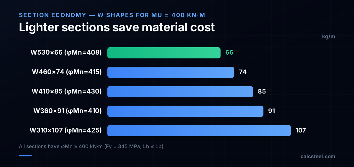
Example comparison for M_u = 400 kN·m
| Section | Weight (kg/m) | φM_n (kN·m) | I_x (10⁶ mm⁴) |
|---|---|---|---|
| W530×66 | 66 | 416 | 351 |
| W460×74 | 74 | 415 | 333 |
| W410×85 | 85 | 430 | 316 |
| W360×91 | 91 | 410 | 266 |
The W530×66 saves 25 kg/m compared to the W360×91 — a 27% weight reduction. For a 9 m beam, that is 225 kg of steel saved per beam. At $2/kg fabricated and erected, that is $450 per beam.
What are common mistakes when sizing steel beams?
After reviewing hundreds of student and professional calculations, these errors appear repeatedly:
1. Forgetting self-weight The beam's own weight is a dead load. A W530×66 adds 0.65 kN/m to the dead load. For light-loaded beams this can be 5-10% of the total load. Add it to the dead load and re-check — if the section changes, iterate.
2. Using S_x instead of Z_x (or vice versa) For LRFD with compact sections, use the plastic section modulus Z_x. For ASD or non-compact sections, use the elastic section modulus S_x. Mixing them up under-sizes or over-sizes the beam by the shape factor (Z/S ≈ 1.12 for W-shapes).
3. Ignoring unbraced length Assuming continuous bracing when the slab is not connected, or when the beam is loaded on the tension flange (hang loads don't brace the compression flange). Always verify what actually provides lateral restraint.
4. Checking only one load combination Combination 2 (1.2D + 1.6L) gives the maximum gravity moment, but combination 6 (0.9D + 1.0W) may create uplift or reverse moment. Check all applicable combinations.
5. Skipping web limit states For beams with concentrated loads (columns bearing on the beam), check web yielding, web crippling, and sidesway web buckling per AISC Chapter J. These can require stiffener plates.
6. Using live load for deflection of total load case The L/360 limit applies to live load deflection alone. The L/240 limit applies to total (D+L) deflection. Using the wrong load with the wrong limit gives a false pass.
How does CalcSteel automate steel beam design?
The manual process above works for one beam. A real structure has dozens or hundreds of beams, each with different spans, loads, and bracing conditions. CalcSteel automates the complete workflow:
Automatic load path Applied loads on slabs and roofs are automatically distributed to supporting beams based on tributary area. No manual takeoff needed.
All load combinations The engine generates all ASCE 7 (or NBR 8800, Eurocode 3) load combinations and evaluates every beam under every combination. The governing combination is identified automatically.
Section optimization For each beam, the optimizer sweeps the section database and selects the lightest section that passes all limit states — flexure, shear, LTB, deflection, and web limit states — in a single pass.
Interactive verification Every check is shown in the results panel with demand/capacity ratios. You can click any beam to see its SFD, BMD, and utilization ratio. If you override the auto-selection with a manual section, the checks update instantly.
Design iteration Changing a beam size updates the self-weight, which changes the load distribution, which may change the controlling combination. CalcSteel re-runs the analysis automatically until the design converges — something that would require multiple iterations by hand.
The result: beam sizing that takes hours by hand completes in seconds, with full code compliance documented in the output report.
Try CalcSteel for free
Model, analyze and design steel structures in your browser. No install, no signup.
Open the 3D editor