Eccentrically Braced Frames: the Link Length Criterion Behind the Code
Eccentrically braced frame design turns on one number: the link length. Here is the criterion behind the code, with a worked check on a real W360×64 link.
Key takeaways
- An EBF's link is a ductile fuse: it yields in shear or bending while the braces, columns and the rest of the beam stay elastic.
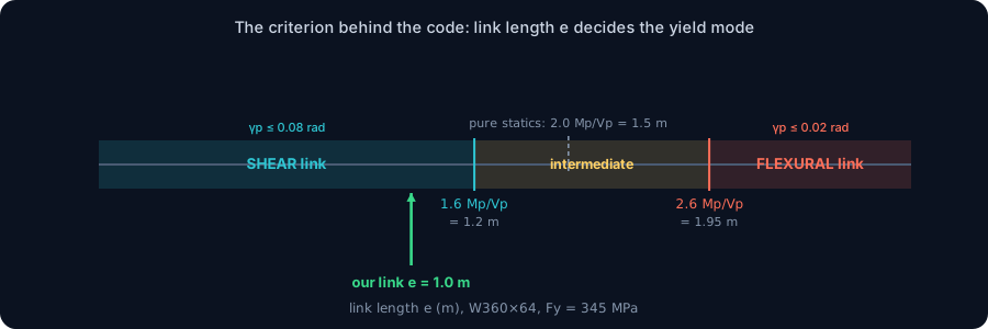
- The link length e is the whole criterion, e ≤ 1.6 Mp/Vp is a shear link, e ≥ 2.6 Mp/Vp is a flexural link, between them is intermediate.
- That boundary comes from statics (Mend = V·e/2); the code brackets the pure-statics value of 2.0 Mp/Vp with 1.6 and 2.6.
- Worked W360×64 shear link: Vp = 510 kN, Mp = 383 kN·m, e = 1.0 m, γp = 0.072 ≤ 0.08 rad, strength and rotation both pass.
- Capacity design sizes everything outside the link for about 1.25 Ry Vn = 701 kN, so only the link yields.
What an eccentrically braced frame really is
An eccentrically braced frame (EBF) looks like an ordinary braced frame with one deliberate imperfection: the brace does not run to the beam-column joint. It stops short, so a small segment of beam, the link, is left between the brace and the column, or between two braces. That offset is not a detailing accident. It is the entire design idea.
Under a severe earthquake the link is engineered to yield first and to keep yielding, absorbing energy cycle after cycle like a ductile fuse, while the braces, the columns and the rest of the beam stay elastic. The result is a system with the lateral stiffness of a concentrically braced frame and the ductility of a moment frame, the best of both, which is why EBFs are a first-choice seismic system.
Here is the part most references bury: the whole EBF chapter of the code turns on one number, the link length e. Get it right and the link yields the way you intended; get it wrong and the fuse either cannot rotate far enough or yields in the wrong mode. This article derives the criterion behind that number, then runs a full worked check on a real section, a W360×64 link, with values computed by the CalcSteel FEM engine. You can reproduce the shear and the moment yourself in the calculator embedded further down.
EBF vs CBF vs moment frame: why the offset
Here is a 45-word definition you can quote: an eccentrically braced frame is a steel lateral system in which each brace meets the beam a short distance from the beam-column joint, creating a stub of beam called the link; under earthquake loading the link yields in shear or bending and dissipates energy while every other member stays elastic.
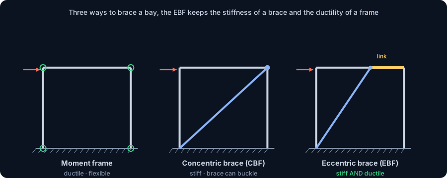
Why go to the trouble? Compare the three ways to brace a bay. A moment frame is ductile but flexible: it drifts a lot, so keeping drift in check is expensive. A concentrically braced frame (CBF) is stiff, but its energy dissipation relies on a slender diagonal buckling and then yielding in tension, a pinched, degrading behaviour. The EBF keeps the diagonal working mostly in axial, so the frame stays stiff, but forces all the inelastic action into the link, whose shear yielding is stable and repeatable. You get CBF stiffness with moment-frame ductility.
New to braced systems? Our overview of bracing systems for steel structures sets the scene. Here we go straight to the number that governs the EBF.
The link is the fuse: capacity design in one picture
The organising principle of EBF design is capacity design: you choose one element to be the weak link, literally, and make everything else strong enough to stay elastic while that element yields fully and strain-hardens. In an EBF the fuse is the link, and its shear yielding is deliberately the weakest mechanism in the frame.
This is why EBFs behave so well. A steel web yielding in shear is one of the most ductile, stable energy dissipators there is: it can rotate through large plastic angles for dozens of cycles without losing much strength, provided it is stiffened correctly. Nothing has to buckle first, unlike the diagonal of a CBF.
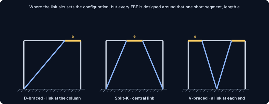
Where the link sits defines the configuration. In a D-braced EBF a single diagonal leaves one link next to a column. In a split-K (chevron) EBF two diagonals meet the beam near midspan, leaving a central link. In a V-braced EBF the links sit next to each column. The mechanics of the link are the same in every case; only the geometry that feeds it changes.
The criterion behind the code, from first principles
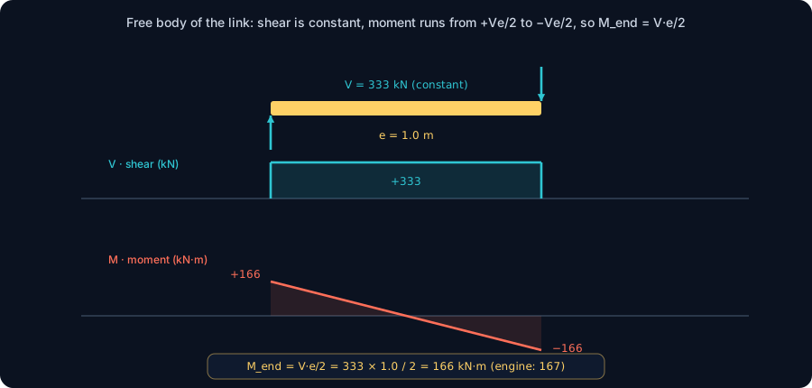
Take the link as a free body. Because the brace delivers its force at the end of the link, the link carries an almost constant shear V along its length e, and the bending moment grows linearly from one end to the other. For a balanced link the moment is equal and opposite at the two ends, so:
Mend = V · e / 2
Now ask which yield happens first as you push the link. It yields in shear when V reaches the plastic shear strength Vp. It yields in bending when Mend reaches the plastic moment Mp, that is, when V·e/2 = Mp, or V = 2Mp/e. Set the two equal to find the length where the mechanisms coincide:
e = 2 Mp / Vp (pure statics)
Shorter than that length, shear governs (a shear link); longer, bending governs (a flexural link). Clean statics puts the boundary at a coefficient of exactly 2.0.
The code does not use 2.0. AISC 341 calls a link a shear link only when e ≤ 1.6 Mp/Vp, and a flexural link only when e ≥ 2.6 Mp/Vp, with an intermediate zone between. That gap straddling 2.0 is the whole point: the flanges carry some shear and the web carries some moment, strain hardening lifts the real shear well above Vp, and the moment gradient matters. So the code brackets the clean statics answer with a “definitely shear” zone below 1.6 and a “definitely flexural” zone above 2.6, and treats the messy transition by interpolation. Where e falls relative to 1.6 and 2.6 times Mp/Vp is the criterion the rest of this article checks.
The two capacities you need: Vp and Mp
The criterion needs two capacities, and both come from the section. The plastic shear strength uses only the web, because in a wide-flange the web carries essentially all the shear:
Vp = 0.6 · Fy · Aw, with Aw = (d − 2tf) · tw
The plastic moment uses the whole section through its plastic modulus Z, not the elastic modulus S. This trips people up: at the link the code wants the fully-plastic capacity, so you use Z, which is 10–15% larger than S for a rolled I-shape:
Mp = Fy · Z
The free-body picture makes Mend = V·e/2 concrete: a rectangular (constant) shear diagram and a linear moment diagram that swings from +V·e/2 at one end to −V·e/2 at the other. Everything in the classification follows from those two capacities and that one geometric relation. Next we put numbers to them.
Worked check, part 1: classify the link
The section
Take a W360×64 link in ASTM A572 Gr.50 / A992 steel (Fy = 345 MPa). From the geometry: d = 347 mm, bf = 203 mm, tf = 13.5 mm, tw = 7.7 mm. Its elastic modulus is Sx = 1003 cm³; the plastic modulus works out to Zx = 1111 cm³, a healthy shape factor of 1.11. (Always confirm Z > S, or you have used the wrong modulus.)
The two capacities
- Web area: Aw = (347 − 2·13.5) · 7.7 = 320 · 7.7 = 2464 mm²
- Plastic shear: Vp = 0.6 · 345 · 2464 = 510 kN
- Plastic moment: Mp = 345 · 1111·10³ = 383 kN·m
Classify
The two code boundaries are 1.6 Mp/Vp = 1.6 · 383 / 510 = 1.20 m and 2.6 Mp/Vp = 1.95 m. The pure-statics crossover sits at 2.0 Mp/Vp = 1.50 m, neatly between them. Choose a link length e = 1.0 m. Since 1.0 m ≤ 1.20 m, it is a shear link, the most ductile class, with a plastic rotation limit of 0.08 rad. As a mode check, the shear that would cause flexural yielding is 2Mp/e = 767 kN, well above Vp = 510 kN, so shear yielding governs and the classification stands.
The nominal link shear strength is Vn = min(Vp, 2Mp/e) = min(510, 767) = 510 kN, and the design strength is φVn = 0.90 · 510 = 459 kN.
Worked check, part 2: the link rotation angle
Classifying the link is only half the criterion. The other half is the link rotation angle γp, the plastic shear angle the link must absorb when the frame reaches its design story drift. This is where a link can quietly fail even though its strength is fine, and it is often what actually governs the link length.
For a split-K (central-link) EBF the kinematics give the link rotation as the story drift amplified by the ratio of bay width to link length:
γp = (L / e) · θp
where L is the bay width, e the link length and θp the inelastic story drift angle. With L = 6.0 m, e = 1.0 m and a design story drift θp = 0.012 rad:
γp = (6.0 / 1.0) · 0.012 = 0.072 rad ≤ 0.08 rad ✓
The shear link passes, with a little room. Notice the trap: the shorter you make the link, the larger the rotation demand, because the same story drift is squeezed into a smaller stub. Push e down to 0.9 m here and γp would hit 0.08 rad exactly; anything shorter and a nominally-strong shear link would be over-rotated. That is why link length has a floor as well as a ceiling, the code's rotation limits (0.08 rad for shear links, 0.02 rad for flexural links, interpolated between) put a lower bound on e that is easy to miss.
See it yourself: the live shear-and-moment tool
The relation M = V·e/2 that drives the whole classification is something you can watch happen. In the calculator below, model a short beam segment, apply equal and opposite shears at its ends, and read off how the moment builds linearly to V·e/2, then shorten the segment and watch the moment shrink while the shear stays put. That is a shear link in miniature.
It is the same engine used for the worked frame in the next section, free, and with no login for the math.
|V| max
30 kN
@ x = 6 m
M max (sagging)
45 kN·m
@ x = 3 m
M min (hogging)
-0 kN·m
@ x = 6 m
Reactions (kN)
R_A 30 · R_B 30
Simply supported beam — uniformly distributed load
Segment equations — x in m, from the left end
0 m ≤ x ≤ 6 m
V(x) = 30 − 10·x [kN]
M(x) = 30·x − 5·x² [kN·m]
Profiles that resist this moment
Md = 45 kN·m → required Wx = Md / (fy/γa1) = 45 kN·m / (250/1.1) = 198 cm³
Bending screen (Wx ≥ Md/(fy/γa1), NBR 8800 γa1 = 1.10 — AISC 360 φb = 0.90 is nearly identical); plastic Zx is valid for compact sections only. δ is the elastic deflection of THIS loading with E = 200 GPa and the section's Ix (loads taken at service value). LTB, shear, compactness and code deflection limits are verified on the profile page and in the 3D editor. "Open in 3D editor" recreates THIS beam — span, supports and every load — with the profile already assigned.
Worked check, part 3: where the demand comes from
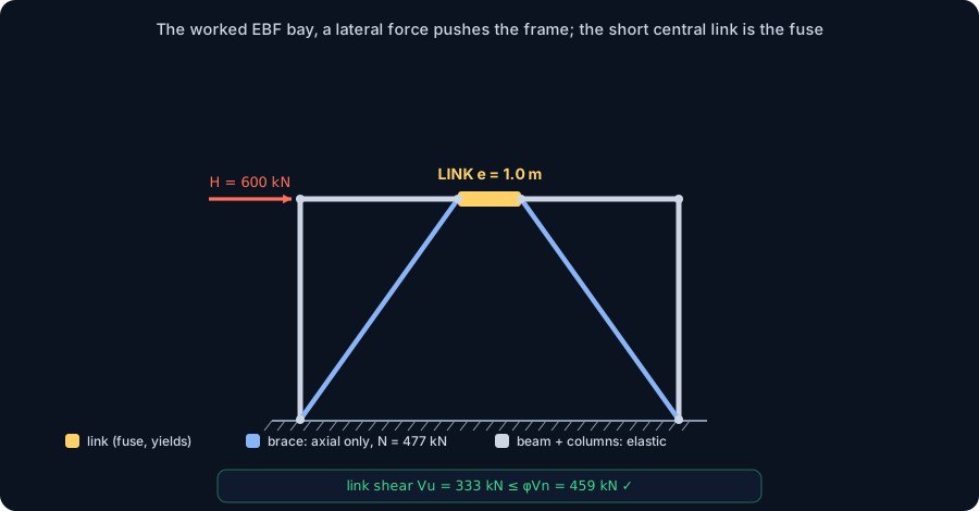
Strength and rotation both check out, but where does the demand come from? An EBF bay is statically indeterminate: the braces, the columns and the link share the lateral load, and the split depends on their relative stiffness. There is no closed form; you need a frame analysis. We built the exact bay from the top of this article in the CalcSteel FEM engine, a 6.0 m chevron EBF, 3.5 m high, W360×64 members, W250×73 braces, fixed bases, and pushed it with a story shear H = 600 kN.
The engine returns:
- Link shear Vu = 333 kN. Against φVn = 459 kN the link is at 73% utilisation, safe, and the governing element as intended.
- Link end moment = 167 kN·m. Hand-check: V·e/2 = 333 · 1.0 / 2 = 166 kN·m. Engine and free-body statics agree to better than 1%, the M = V·e/2 relation behind the whole criterion is not an approximation, it is what the frame actually does.
- Brace axial = 477 kN, with almost no bending: the diagonal is a strut, exactly as capacity design wants it.
- Base reactions balance the applied shear (ΣFx = 600 kN) and form the overturning couple (±333 kN vertical), a quick global-equilibrium check.
This is the kind of indeterminate frame that used to mean a desktop licence. CalcSteel solves it in the browser: open the shear-and-moment tool or build the full bay in the editor and read the same numbers.
Protecting the rest: capacity design
The link is the fuse; capacity design makes sure it is the only fuse. Every other element must survive the link not just yielding but strain-hardening well past Vp. AISC 341 does this with the link's expected shear strength, using an expected-to-nominal yield ratio Ry (1.1 for A992 / A572 Gr.50):
- Expected link shear: RyVp = 1.1 · 510 = 561 kN.
- The diagonal brace, the beam segment outside the link and their connections are designed for the forces produced by the link reaching about 1.25 · Ry · Vn = 701 kN, the 1.25 accounts for strain hardening. That is roughly 1.4× the elastic demand, and it is deliberate: the brace must never be the weak point.
- Columns are designed for the sum of the link capacities they carry over the height, so they stay elastic in the full mechanism.
- The link itself needs web stiffeners at a spacing set by the target rotation, plus a stiffener at the brace end, to keep the shear-yielding web stable to 0.08 rad without buckling. Skip them and the ductile behaviour the whole system relies on simply does not develop.
Codes: this check follows AISC 341-16 §F3; Eurocode 8 (EN 1998-1) §6.8 uses the same link idea with its own symbols and an overstrength factor Ω. In Brazil, member design follows NBR 8800 and seismic detailing NBR 15421; seismic demand is low across most of the country, but the EBF link logic is identical wherever the load comes from.
Common mistakes & FAQ
The mistakes that most often turn a textbook-correct EBF into a failed check:
- Using the elastic modulus S for Mp. The link's plastic moment uses the plastic modulus Z. Confusing the two under-counts Mp by 10–15% and shifts every classification boundary.
- Forgetting the rotation floor. A shear link that is too short over-rotates. Always check γp = (L/e)·θp against 0.08 rad, not just the strength.
- Using the wrong rotation kinematics. The L/e factor here is for a central (split-K) link. A link next to a column, or a two-link V-brace, has a different geometric factor, take it from your configuration, do not copy ours blindly.
- Designing the brace for the analysis force. Capacity design sizes the brace, beam and columns for the link's expected, strain-hardened strength (≈ 1.25 RyVn), not the elastic demand from the load case.
- Omitting the link stiffeners. No stiffeners, no stable shear yielding, the web buckles and the ductility evaporates.
- Making the link composite. A slab cast tight against the link changes its strength and rotation; links are detailed to keep the slab from restraining them.
FAQ
Is a shear link or a flexural link better? Shear links (e ≤ 1.6 Mp/Vp) are preferred: shear yielding is more ductile and the rotation limit is four times higher (0.08 vs 0.02 rad). Flexural links are used when architecture forces a long link.
Why is an EBF stiffer than a moment frame? The diagonal carries lateral load in axial rather than bending, so the frame is far stiffer for the same steel, you meet drift limits with lighter members.
Can I use an EBF where seismic demand is low, like most of Brazil? Yes, the link logic applies to any lateral load. In low-seismic zones the demand is small, but the EBF's stiffness plus ductility can still be the efficient choice.
Key takeaways
The eccentrically braced frame is one idea executed carefully: put a short, ductile fuse, the link, in the load path, and protect everything around it.
- The link length e is the criterion. e ≤ 1.6 Mp/Vp is a shear link (γp ≤ 0.08 rad); e ≥ 2.6 Mp/Vp is a flexural link (≤ 0.02 rad); between them is intermediate.
- The criterion comes from statics: Mend = V·e/2, so shear governs below e = 2.0 Mp/Vp, and the code brackets that with 1.6 and 2.6.
- Our W360×64 shear link (Vp = 510 kN, Mp = 383 kN·m, e = 1.0 m) has γp = 0.072 rad, both checks pass, verified by the CalcSteel engine (link shear 333 kN, M = V·e/2 confirmed).
- Capacity design does the rest: everything outside the link is sized for about 1.25 RyVn so only the link yields.
Want to try the numbers on your own section? The shear-and-moment calculator and the full CalcSteel editor are free to use, and CalcSteel is free for students. Build the bay, read the link shear, and check it against φVn yourself.
Sources
- 1.AISC 341-16, Seismic Provisions for Structural Steel Buildings (§F3, EBF)
- 2.Eurocode 8 (EN 1998-1) §6.8, Design of structures for earthquake resistance
- 3.Popov & Engelhardt, Seismic eccentrically braced frames (J. Constructional Steel Research, 1988)
- 4.Bruneau, Uang & Sabelli, Ductile Design of Steel Structures (2nd ed., 2011)
- 5.ABNT NBR 8800 / NBR 15421, Projeto de estruturas de aço e resistência sísmica
Try CalcSteel for free
Model, analyze and design steel structures in your browser. No install, no signup.
Open the 3D editor