Column vs Beam vs Brace: One Frame, Three Jobs
A steel frame can look like a uniform lattice of identical members, but each one is doing a fundamentally different job. A column resists being crushed, a beam resists being bent, and a brace resists being pushed sideways — and the design code checks each against a different failure mode. This is the history and the physics behind that three-way split, and exactly how software turns it into a pass/fail verification.
Key takeaways
- A column carries axial compression and is governed by buckling; a beam carries bending and is governed by flexure and lateral-torsional buckling; a brace carries pure axial force to resist lateral loads.
- The math is old: Euler derived the column buckling load in 1744, and Navier completed elastic-limit beam theory by 1826 — yet steel construction only made the formulas practically essential a century later.
- Modern codes (AISC 360, Eurocode 3, NBR 8800, IS 800) reduce each member to a demand/capacity ratio; members that do two jobs at once are checked with an interaction equation.
- Browser-native tools like CalcSteel run the finite-element analysis and the per-member code check without a desktop install.
Three members, three jobs
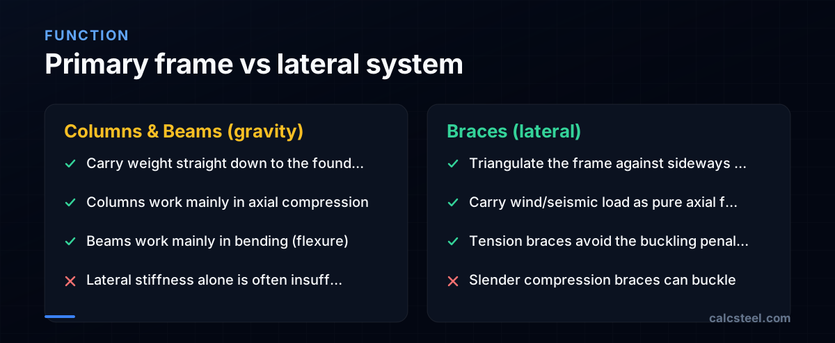
Start with what each member does, because the rest follows from it. A column is a vertical compression member: its main task is to take the weight collected by the floors above and deliver it straight down to the foundation. A beam spans horizontally between supports and resists bending — the load tries to sag it, putting one face in tension and the other in compression. A brace is the diagonal that triangulates the frame so it does not lean over under wind or earthquake.
The clean way to remember it: columns and beams form the gravity system that carries weight downward, while braces form the lateral system that carries sideways load to the ground. The primary beam-and-column frame is optimized for gravity, but its resistance to being pushed sideways is often insufficient on its own — which is precisely why braces exist.
Why the failure modes differ
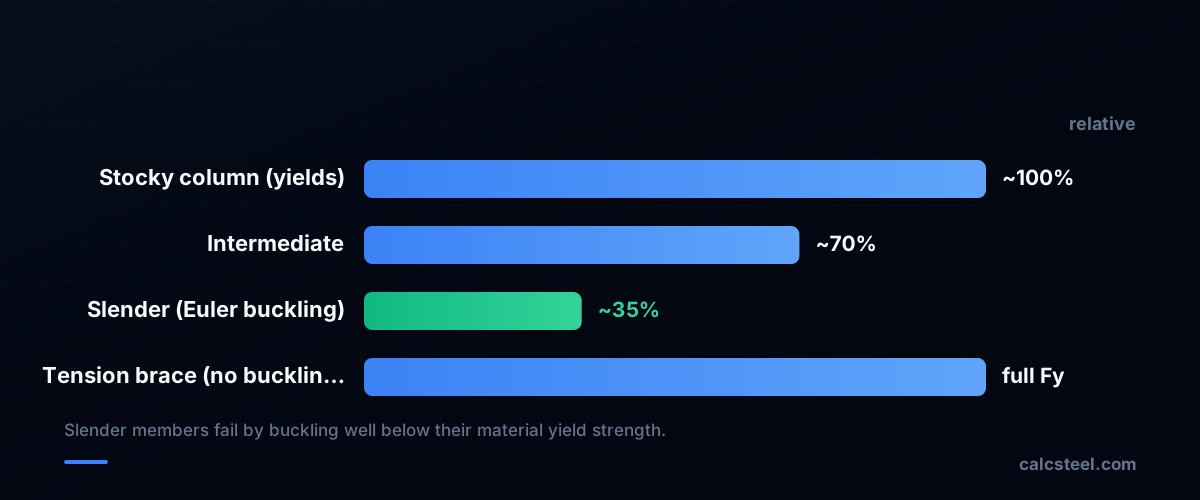
The reason these members are designed differently is that they fail differently. A short, stocky column simply crushes when the stress reaches the steel's yield strength. But a slender column fails far earlier by buckling — bowing sideways and losing stability long before the material yields. A tension brace has no such problem: you cannot buckle something you are pulling on, so a brace in tension can develop its full yield capacity.
This is why engineers say buckling is a stability problem, not a strength problem. The classic Euler result makes the point bluntly: the critical buckling load depends only on stiffness (the modulus E) and geometry (the moment of inertia I and the length), not on the steel's strength. Make a column more slender and its capacity collapses even though the material is unchanged. That single insight is why columns, beams and braces each get their own check.
An 18th-century formula that waited for steel
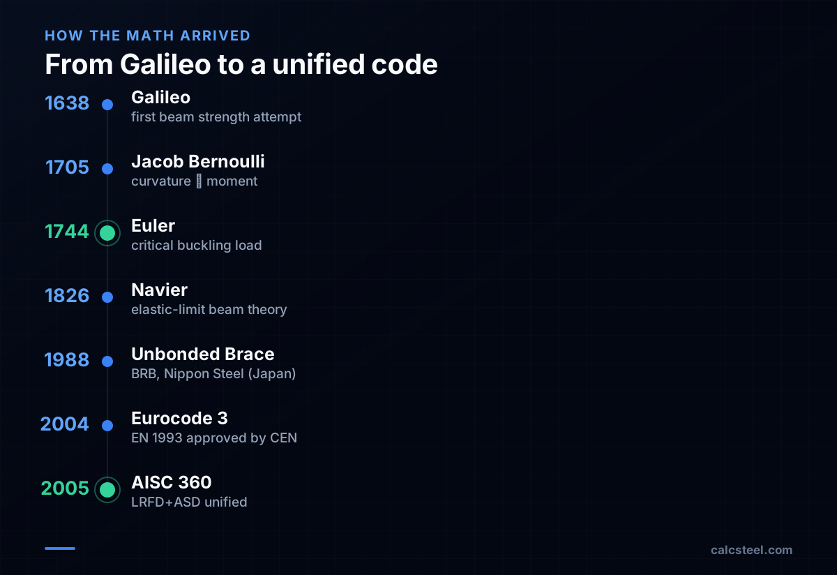
The mathematics behind these members is surprisingly old. Galileo made the first recorded attempt at a beam-strength theory in 1638 (his result was about three times too high because he assumed uniform stress and rotation about the base of the section). Jacob Bernoulli postulated in 1705 that a beam's curvature is proportional to its bending moment. Around 1750, Leonhard Euler and Daniel Bernoulli assembled what we now call Euler–Bernoulli beam theory, and in 1744 Euler derived the critical buckling load for a column. Navier completed the elastic-limit beam theory used by working engineers by 1826.
Yet the column formula found little practical use for well over a century. Eighteenth-century structures used stocky, brittle members whose real failure loads fell well below Euler's prediction, so practicing engineers had little use for it — and later experimentalists (Lamarle in 1845, Considère in 1889) had to map out where the elastic formula actually applied. Only when steel construction (and later aircraft) produced genuinely slender compression members did Euler's buckling theory become indispensable. The brace's modern form arrived even later: the buckling-restrained brace (BRB) was developed in Japan by Nippon Steel at the end of the 1980s under the trademark Unbonded Brace, and was first installed in the United States in 1999, at UC Davis.
How design codes turn it into a check
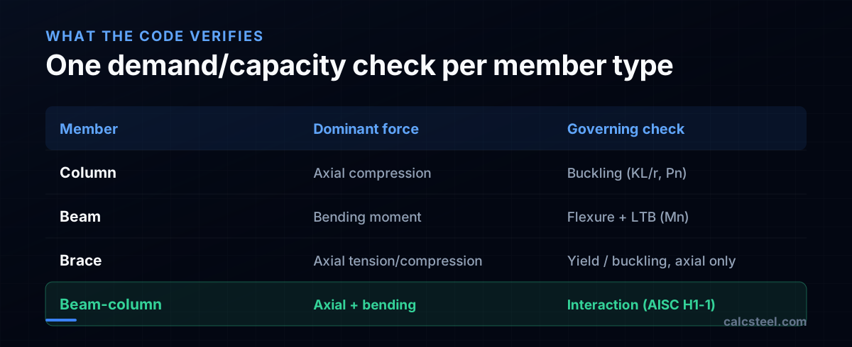
Modern steel codes reduce each member to a demand/capacity ratio: compute the force the member must carry, compute the capacity the code allows, and require the ratio to stay at or below 1.0. The capacity formula is what changes by member type.
- Column: the code computes the nominal compressive strength using the slenderness ratio KL/r — where K is the effective-length factor (theoretically 1.0 pinned-pinned, 0.5 fixed-fixed, about 0.7 fixed-pinned, 2.0 fixed-free) — to capture buckling.
- Beam: the code computes the nominal flexural strength, including a check for lateral-torsional buckling when the compression flange is unbraced.
- Brace: a pure axial member — checked for tension yield/rupture or, in compression, for buckling. Tension is preferred precisely because it sidesteps the buckling penalty.
These rules are codified across regions: AISC 360 in the US (the 2005 edition was the first to integrate LRFD and ASD into a single specification), Eurocode 3 / EN 1993 in Europe (EN 1993-1-1 was approved by CEN on 16 April 2004), and the national standards NBR 8800 (Brazil) and IS 800 (India). The philosophies differ in detail but share the same demand/capacity logic.
When a member does two jobs: the interaction check
Real frames blur the categories. A perimeter column in a moment frame carries axial load and bending; a beam in a braced bay can pick up axial force from the brace. The code handles these beam-columns with an interaction equation that adds the axial and bending demands together.
In AISC 360 this is the H1-1 pair. When the axial ratio Pr/Pc is at least 0.2, equation H1-1a applies: Pr/Pc + (8/9)(Mrx/Mcx + Mry/Mcy) ≤ 1.0. When Pr/Pc is below 0.2, H1-1b applies: Pr/(2Pc) + Mrx/Mcx + Mry/Mcy ≤ 1.0. Here Pr and Pc are required and available axial strengths, and the M terms are the bending demands and capacities about each axis. Eurocode 3 uses its own, more elaborate interaction formulae, but the intent is identical: no single member may be quietly overloaded by the combination of forces.
From concept to a verified model
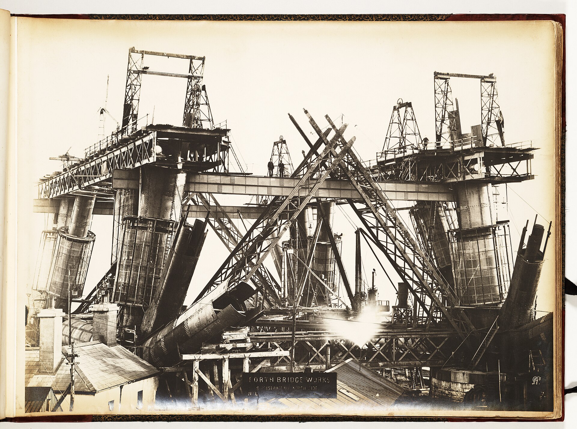
So the three members are not arbitrary labels. A column is an axial-compression member governed by buckling; a beam is a flexural member governed by bending and lateral-torsional buckling; a brace is a pure axial member that triangulates the frame against lateral load. Where they overlap, an interaction equation keeps the combined demand honest.
Doing this by hand for every member — classifying it, picking the right capacity formula, then chasing the demand/capacity ratio across dozens of load combinations — is what made structural verification slow. Browser-native tools like CalcSteel collapse the loop: build the model, run the finite-element analysis, and read back a per-member code check, so the difference between a column, a beam and a brace stops being a definition to memorize and becomes a result you can see.
Sources
- 1.Euler's critical load — Wikipedia
- 2.Buckling-restrained brace — Wikipedia
- 3.The new 2005 AISC specification (unified LRFD + ASD)
- 4.EN 1993-1-1: Eurocode 3: Design of steel structures (approved by CEN 16 April 2004)
- 5.Historical development of the beam bending equation (Galileo, Bernoulli, Navier)
- 6.Column Buckling — effective length factors (MechaniCalc)
- 7.Image: Philip Phillips (photographer) — Public domain (Wikimedia Commons)
Try CalcSteel for free
Model, analyze and design steel structures in your browser. No install, no signup.
Open the 3D editor