Bracing Systems in Steel Structures: Types
Learn about steel bracing systems: X-bracing, chevron, moment frames, and eccentrically braced frames. Covers drift limits, brace design forces, and when to use each system.
What is a bracing system in a steel structure?
A bracing system is the collection of structural elements that resist lateral forces — wind, seismic, and notional loads — and transfer them to the foundation. Without a bracing system, a steel frame would collapse sideways under even moderate lateral loads.
Every building needs a complete lateral force-resisting system (LFRS) in at least two orthogonal directions. The choice of system affects: - Stiffness: How much the building sways (drift) - Strength: The maximum lateral load the frame can resist - Ductility: How much energy the frame can absorb before failure - Architecture: Whether openings and corridors are obstructed
The three primary systems are: 1. Braced frames — Diagonal members carry lateral forces as axial loads 2. Moment frames — Rigid beam-column connections resist lateral forces through bending 3. Shear walls — Steel plate or concrete walls act as vertical cantilevers
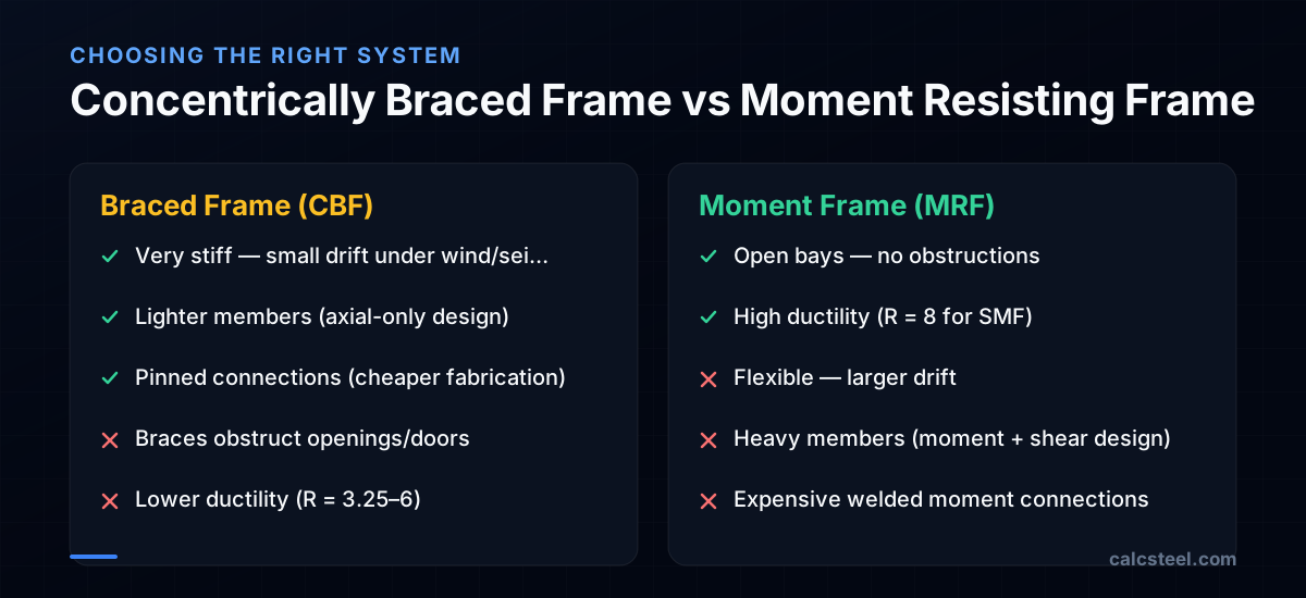
Most steel buildings use braced frames because they are stiff, efficient, and economical. Moment frames are used when architectural requirements preclude diagonal braces.
What types of braced frames are used in steel buildings?
Braced frames are classified by the geometry of the diagonal members:
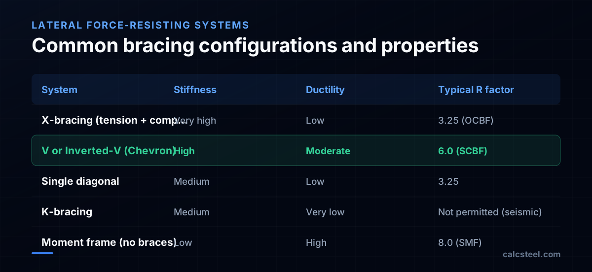
X-bracing (cross bracing) Two diagonals form an X in the bay. One diagonal is in tension while the other is in compression for any direction of lateral load. This is the stiffest configuration because both diagonals participate. Common in low-rise industrial buildings where architectural constraints are minimal.
Chevron bracing (V or inverted-V) A single V (or inverted V) connects the beam midpoint to the columns at floor level (or vice versa). The beam must be designed for the unbalanced vertical force when one brace buckles. AISC 341 (seismic) requires the beam to resist the full tension yield of one brace plus 30% of the post-buckling capacity of the other.
Single diagonal One diagonal per bay, alternating direction between floors to avoid cumulative drift in one direction. Simple but less stiff than X-bracing. Acceptable for wind-only design (non-seismic).
K-bracing Diagonals meet at the column midheight. Not permitted in seismic design because column failure at the brace intersection would cause progressive collapse. Only used in low-seismic regions with wind governing.
Eccentric bracing (EBF) The diagonal connects to the beam away from the column, creating a short "link" segment in the beam. The link yields in shear, providing ductility while the rest of the frame stays elastic. R = 8.0 — same ductility as moment frames but much stiffer.
How do you design a diagonal brace member?
Diagonal braces carry the lateral shear as axial force (tension or compression). The design depends on whether the connection allows the brace to resist both tension and compression (bearing-type) or tension only.
Compression brace design (AISC Chapter E)
The brace must resist the factored lateral force resolved along the diagonal:
P_u = V_story / (n × cos θ)
Where V_story is the story shear, n is the number of braces in the story, and θ is the brace angle from horizontal.
Example — Single-story X-braced bay
- Bay width: 6 m, story height: 4 m
- Brace length: √(6² + 4²) = 7.21 m
- Brace angle: θ = arctan(4/6) = 33.7°
- Story shear: V_u = 150 kN
- Brace force: P_u = 150 / (2 × cos 33.7°) = 150 / 1.664 = 90.1 kN per brace
For a compression brace, check buckling: - Try HSS 127×127×6.4: A = 2850 mm², r = 48.5 mm - KL/r = 1.0 × 7210 / 48.5 = 148.7 - F_cr (elastic range): 0.877 × π²(200000)/(148.7)² = 0.877 × 89.3 = 78.3 MPa - φP_n = 0.90 × 78.3 × 2850 × 10⁻³ = 201 kN > 90.1 kN ✓
Tension-only bracing
In some configurations, only the tension diagonal is considered effective (the compression diagonal buckles and is ignored). This doubles the brace force: P_u = 150 / (1 × cos 33.7°) = 180.3 kN. Tension-only bracing uses lighter members (rods or small angles) but requires twice as many braces.
What are the drift limits for steel frames under lateral loads?
Drift is the lateral displacement of one floor relative to the floor below. Excessive drift damages partitions, cladding, and causes occupant discomfort.
Wind drift limits
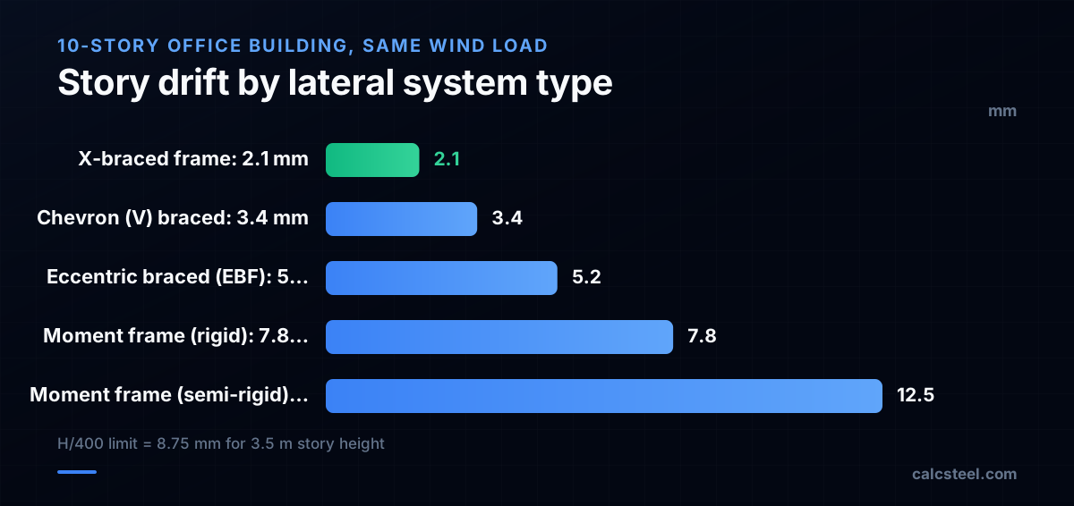
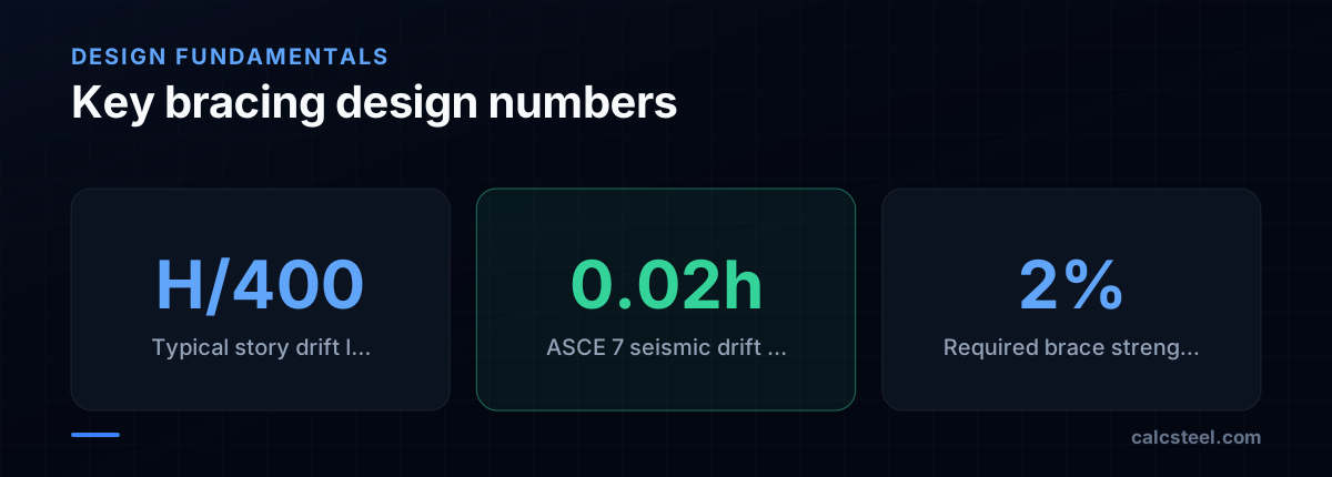
No single code mandates wind drift limits, but common practice follows: - H/400 per story (most office buildings) - H/600 for sensitive occupancies (hospitals, labs) - H/200 for industrial buildings with flexible cladding
Where H is the story height.
Seismic drift limits (ASCE 7-22 Table 12.12-1)
- Risk Category I-II: 0.020 × h_sx (2% of story height)
- Risk Category III: 0.015 × h_sx
- Risk Category IV: 0.010 × h_sx
Seismic drift is checked using amplified displacements: δ_x = C_d × δ_xe / I_e, where C_d is the deflection amplification factor and δ_xe is the elastic displacement from the reduced seismic force.
How to reduce drift
- Stiffen the bracing — Use larger brace sections or add more braced bays
- Add outrigger frames — Connect the core to perimeter columns at mechanical floors
- Increase column stiffness — Larger columns reduce frame flexibility
- Use dual systems — Combine braced frames and moment frames; the interaction reduces drift below what either system alone achieves
Drift often governs the design of tall buildings even when strength is satisfied. For buildings over 10 stories, drift checks should be done early to avoid late redesigns.
When should you use a moment frame instead of braced frame?
Moment frames resist lateral forces through rigid beam-column connections (no diagonal braces). They are used when:
Architectural reasons - Open floor plans with no obstructions between columns - Large storefronts or window walls that cannot accommodate diagonal braces - Corridors that must pass through braced bays - Building facades where diagonal braces are not acceptable aesthetically
Seismic design advantages - Special Moment Frames (SMF) have R = 8.0, the highest response modification factor - High ductility through controlled yielding of beam plastic hinges - No brace buckling issues (a concern in CBFs during large earthquakes)
Disadvantages - Much more flexible than braced frames — drift often governs - Heavier beam and column sections required to resist bending - Expensive welded moment connections (complete joint penetration welds) - Column panel zone must be checked for shear (often requires doubler plates)
Combined systems
Many buildings combine both systems: - Braced frames at the core (around elevators/stairs) - Moment frames at the perimeter (for architectural openness)
This dual system provides high stiffness from the braced core and high ductility from the moment frame. ASCE 7 allows a higher R factor for dual systems when the moment frame can independently resist at least 25% of the design seismic force.
How do you design bracing connections?
Brace connections must transfer the full brace force (tension and compression) while accommodating brace rotation during buckling. The gusset plate is the critical element.
Gusset plate design
The gusset plate connects the brace to the beam-column joint. Design checks:
- Whitmore section — The effective width at the end of the bolt group or weld: W = 2 × L_g × tan(30°) + w_brace. Check tension yielding: φR_n = 0.90 × F_y × W × t_g.
- Gusset buckling — The unbraced length from the end of the brace to the beam/column edge. Use the Thornton method: average of L₁, L₂, L₃ (distances to nearest supports). Check compression: φR_n = φ × F_cr × W × t_g.
- Block shear — Along the bolt pattern or weld group.
- Beam and column checks — The gusset transfers forces into the beam and column. Check local web yielding, web crippling, and flange bending at the gusset interface.
Brace-to-gusset connection
For HSS braces: slot the tube end and insert the gusset, then fillet weld on both sides. The weld length must develop the brace force with the shear lag factor U applied.
For angle or W-shape braces: bolt or weld to the gusset plate. Check net section rupture with the appropriate U factor.
Seismic detailing
For SCBF (Special Concentrically Braced Frames), AISC 341 requires: - Connection must resist the expected brace yield strength R_y × F_y × A_g in tension - Must accommodate brace buckling rotation (2t linear clearance from gusset fold line) - Net section reinforcement when U × A_n < A_g
What is stability bracing and how much force does it require?
Beyond the lateral-force-resisting system, individual members need stability bracing to prevent buckling. AISC Appendix 6 defines two types:
Relative bracing A brace that controls the relative movement between two points on a member. Example: horizontal struts between adjacent truss bottom chords.
Required strength: P_br = 0.004 × P_r (0.4% of the axial load in the braced member) Required stiffness: β_br = 2P_r / (φ × L_b)
Nodal (point) bracing A brace that prevents lateral displacement at a single point. Example: a kicker from a floor beam to the bottom flange of a crane girder.
Required strength: P_br = 0.01 × P_r (1% of the axial load) Required stiffness: β_br = 8P_r / (φ × L_b)
Beam lateral bracing For beams in flexure, the compression flange needs lateral bracing to prevent lateral-torsional buckling. The bracing force is based on the maximum compressive force in the flange: C_f = M_r / h_o.
Common stability bracing elements
- Purlins and girts brace roof beams and wall columns
- Floor diaphragms (metal deck + concrete) brace all floor beams
- Fly bracing (diagonal kickers from purlins to rafter bottom flanges) brace portal frame columns
- Sag rods brace purlins and girts between frames
Stability bracing is often overlooked in design but is essential. A beam designed with L_b = purlin spacing needs those purlins to actually provide lateral restraint — if the purlin connection cannot resist the bracing force, the beam is unbraced.
How does CalcSteel model bracing systems?
CalcSteel integrates lateral system design into the 3D modeling and analysis workflow:
Bracing input Diagonal braces are modeled as standard members with pinned end releases. The software automatically identifies braced bays and classifies the frame as braced or unbraced for each direction.
Lateral load application Wind loads (per ASCE 7, Eurocode 1, or NBR 6123) are generated automatically from the building envelope. Seismic loads are computed using the equivalent lateral force method or modal response spectrum analysis.
Drift check Story drift is computed and displayed for every load combination. The engineer sets the drift limit (H/400, H/600, or custom), and the results flag any story that exceeds it.
Brace design Each brace is checked per AISC Chapter E (compression) and Chapter D (tension). The connection forces are output for gusset plate design. For seismic design, the expected yield strength (R_y × F_y × A_g) is reported for connection capacity design.
Stability bracing The engine identifies which members act as stability bracing and checks that the bracing forces per Appendix 6 can be transferred through the connections.
Optimization If drift exceeds the limit, the optimizer suggests stiffer brace sections. If a brace fails in compression, it suggests a section with adequate KL/r. The optimizer works across all braced bays simultaneously, finding the lightest solution that satisfies both strength and drift.
Try CalcSteel for free
Model, analyze and design steel structures in your browser. No install, no signup.
Open the 3D editor